Advertisement
Description
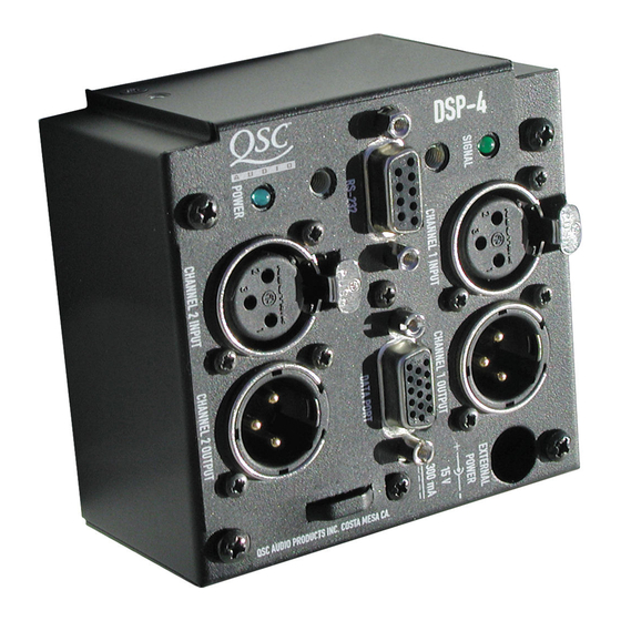
When a DSP-4 unit is mounted directly to a QSC single DataPort equipped amplifier and the two long screws shown in Figure 1 are
tightened, the torque bends the two internal PCB boards slightly. This causes the leads from U7 (a 20-pin DIP microcontroller) to
touch the top of capacitors C42 and C45, causing communication and audio problems. To correct this inadvertent connection, trim all
20 of U7's lead pins.
Symptoms
When mounted directly to a QSC single DataPort-equipped
amplifier and the two #4-40 screws shown in Figure 1 are tight-
ened, the DSP-4 may exhibit any of these problems:
• Loss of RS-232 communication with the computer and the
Signal Manger software
• A thump on the output signals during turn off.
• A buzz in the output signals.
Instructions
Tools and materials required:
• #2 Philips screwdriver
• Small boxes or compartments (to hold assorted screws during
disassembly)
• Small diagonal cutters
Caution: Take appropriate anti-static measures to guard against damage from electrostatic discharge (ESD).
Procedure: Trimming the leads on the microcontroller U7
Gaining access to the IC
1.
Disconnect the DSP-4 from the amplifier.
2.
Remove all 14 screws on the front panel of the DSP-4. Turn the DSP-4 on its
side and remove the other two screws, then flip the DSP-4 over (Data Port
receptacle side) and remove the remaining ones. Note that there are four
different screw sizes.
3.
Gently and carefully pull the chassis apart and remove the printed circuit
board (PCB) assembly.
4.
Separate the two PC boards and locate the one with the QSC part number
that begins with WP-000411- .
5.
Locate the microcontroller U7. See Figure 2.
6.
Use small diagonal cutters to trim all 20 leads of U7.
DSP0009 rev. A.
DSP-4 RS-232 Communication/Turn-Off Thump
Title:
Bulletin #:
DSP0009
Issue Date:
July 27, 2006
Models Affected:
DSP-4
Bulletin Revision:
Rev. A
Production Range:
05/2001 through 05/2006 (serial numbers 0501xxxxx–0506xxxxx)
Figure 1. The problems may occur when these two screws
are tightened.
Service Bulletin
Figure 2. Locate the microcontroller U7.
Continued on next page ➜
1
Advertisement
Table of Contents

Related Manuals for QSC DSP-4


Summary of Contents for QSC DSP-4
- Page 1 Description When a DSP-4 unit is mounted directly to a QSC single DataPort equipped amplifier and the two long screws shown in Figure 1 are tightened, the torque bends the two internal PCB boards slightly. This causes the leads from U7 (a 20-pin DIP microcontroller) to touch the top of capacitors C42 and C45, causing communication and audio problems.
-
Page 2: Contact Information
Figure 3. Connect the DSP-4 to the computer via the 9-pin serial port. Procedure: Testing the DSP-4 Mount the DSP-4 to the rear of a QSC CX, DCA, PL2, or SRA Series amplifier equipped with a single DataPort (Figure 1). Install the two long screws next to the DataPort.
Need help?
Do you have a question about the DSP-4 and is the answer not in the manual?
Questions and answers