
Related Manuals for ProSpot Fitness FUSION HG-5


Summary of Contents for ProSpot Fitness FUSION HG-5
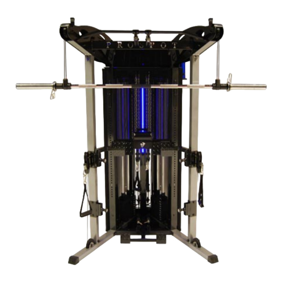
- Page 1 PROSPOTfitness® Fusion Model HG-5 Owners Manual Serial Number: ____________________HG5...
-
Page 2: Table Of Contents
HG-5 Owners Manual Table of Contents Assembly Instructions……………………..…………………………..……..2-17 Use and Operation of Your PROSPOTfitness® Product….………………..18-22 Periodic Maintenance of your PROSPOTfitness® Product……………….… 23 Parts List…………………………………………………….………………..24-25 Trouble Shooting……………………………………………………………..26-28 Warranty & Contact Information……………………………………….…….…29 Note this unit consists of six total boxes: Three Boxes Labeled Box 1-3, HG-5 & 6 Base unit common parts One Box Labeled Box 4, HG-5 Kit Conversion Two Weight stack boxes labeled plates 20-100 lbs -- 2 --... - Page 3 Instructions for Assembly of the ProSpotfitness® HG-5 • Before assembly, choose a safe location for your PROSPOTfitness® HG-6. The PROSPOTfitness® HG-5 has a footprint of approximately 8’x 8’. The surface should be level and even. The barbell is approximately 7’ long. Locate your PROSPOTfitness® HG-5 away from any source of water. Do not allow any liquid to be near the machine or spilled on any electrical part.
- Page 4 Instructions for Assembly of the ProSpotfitness® HG-5 Step #1 MAIN FRAME ASSEMBLY 1. Referencing Diagrams 1 & 2, find the part Front Cross Brace (3). The Wire Harness (108) that runs thru this part. This may be packed in this Cross Brace to prevent damage. Pull on ties and harnesses so that connector ends hang loose out of access holes.
- Page 5 Instructions for Assembly of the ProSpotfitness® HG-5 (con’t.) Step #3 FINAL FRAME ASSEMBLY 1. Now according to Diagram 3 install the Middle Cross Brace (18) using M10*65 Bolts (100), M10 Washers (70 and M10 Nuts (82). 2. Next find the Front Top Rail (27) and attach the Front Panel Tabs (49) to the back of the Rail using Pan Head Bolts M4*10 (118) &...
- Page 6 Instructions for Assembly of the ProSpotfitness® HG-5 (Con’t.) Step #4 WEIGHT BAR ASSEMBLY 1. Now its time to install Sensor Weight Bar (34). Reference Diagram 11. Using a 5mm allen wrench remove the M8*40 Screw (121) Head Screw & End Cap (45) off each end. Now using a 4mm allen wrench, remove the Spacer Collar (48) from each end of Sensor Weight Bar.
- Page 7 Instructions for Assembly of the ProSpotfitness® HG-5 (Con’t.) Step #6 MESH COVERS & ACCESSORIES 1. Referencing Diagrams (1 & 12) first attach the Side Mesh Cover Frames (28 & 29) one side at a time. Set Side Frame on the hooks near the base of the unit. One hook is part (69) and the other hook is on the Rear Bottom Panel (5).
- Page 8 HG-5 Diagram 1 Main Frame Assembly...
- Page 9 HG-5 Diagram 2 Wiring Assembly...
- Page 10 HG-5 Diagram 3: Main Upper Frame Assembly...
- Page 11 HG-5 Diagram 4: Top Panel Assembly...
- Page 12 HG-5 Diagram 5: Weight Stack Diagram...
- Page 13 HG-5 Diagram 6: Middle Cross Brace Assembly...
- Page 14 HG-5 Diagram 7: Cable Run Assembly Detail...
- Page 15 HG-5 Diagram 8: Lat Leg Hold Down Assembly Diagram...
- Page 16 HG-5 Diagram 9: Mesh Panel Frame Assembly...
- Page 17 HG-5 Diagram 10: Weight Bar & Accessories Assembly Detail...
-
Page 18: Use And Operation Of Your Prospotfitness® Product
!!Read!! This Page Before Using Your ProSpotfitness ® Product Safe Use of Your ProSpotfitness® Product CAUTION: This machine involves the risk of possible injury by its user. THE FOLLOWING RULES SHOULD BE CARFULLY FOLLOWED: • Consult a physician or other healthcare provider before beginning an exercise program. - Page 19 User Instructions for the HG-5 Touch Sensor Barbell Operation 1. Rotate the barbell so that the Touch Sensor Strip embedded in the barbell is touching your fingertips. It is necessary for your fingertips to maintain skin contact with the Touch Sensor Strip throughout your free-weight exercise.
- Page 20 User Instructions for the HG-5 (cont’) Storage of Accessories: • There Accessory hooks on the side of the Upper Linking plates for storing the two sets stirrup handles, Nylon Rope. • Weight Plate Tree with accessory hooks and holders for Lat Leg hold down Bar, VKR handles, T-bar, & Lat Bar •...
- Page 21 User Instructions for the HG-5 (cont’) VKR & Dip Station Exercises: • VKR Exercise Place right & left VKR Attachments in receivers on Cable Head Assemblies. Attach Padded Back Rollers in Cross Frame in center position and lock with Pin. With your lower back against the Back Pad Roller Place elbows on the VKR Arm Pads, grab vertical handles and perform exercise by lifting legs or knees up.
- Page 22 User Instructions for the HG-5 (cont’) Using optional FS-150 Bench: • Leg Extension: 1. Set Selector Pin on each Weight Stack to 10lbs. 2. Adjust Foot Board to the second hole by pulling on Pop Pin Knob. 3. Then attach the long Bench Cables to the low-pulley connection using two cable clips on each. Make sure the cable is taut by pulling out the bench until there is no slack in the cable.
-
Page 23: Periodic Maintenance Of Your Prospotfitness® Product
Maintenance Program The HG-5 is made of durable materials and has been factory tested to assure proper function and reliability. It is designed in a way to allow easy replacement of parts both mechanical and electrical if the need should ever arise. -
Page 24: Parts List
Prospot Fitness Fusion HG-5 Parts List Page 1 Part# Description Part# Description Left Base Rail Barbell 50mm Rubber Bumper Right Base Rail Locking Barbell Spacer Front Cross Base Rail Front Panel Tabs Plastic Bottom Panel Cup holder Rear Bottom Panel... - Page 25 Prospot Fitness Fusion HG-5 Parts List Page 2 Description Description Part# Part# Medium Single Groove Pulley Locking Block DBL Pulley Pin Rubber 48mm Bumper Prospot Letters (set) Hex Head Bolt M12*85 Extension Chain Square End Cap Hex Head Bolt M12*70...
-
Page 26: Trouble Shooting
Trouble-Shooting How the Patented ProSpot System works: Starting from the Computer Brain, a signal is sent from the left & right side, thru the L & R Grey Base Frame Wire Harness (white lead), Locking Post wire harness to the Lower rear Cable Knuckle connector, to inside Barbell Cable to the Sensor on the Barbell. - Page 27 Trouble-Shooting (con’t) Before performing the trouble shooting on this page, go thru the Electrical Service Inspection on the previous page. Symptom: Sensor Weight Bar locks prematurely during work out. Solution: 1. Perform Adjustments on Weight Bar / Cable-Knuckle assembly. See Diagram page 28. 2.
-
Page 29: Warranty & Contact Information
Lawrenceville, GA 30043 Office (770) 446-9299 (770)-446-7213 Contacting ProSpot Fitness Technical Support: Our Service Department can be reached M-F 9-5 pm EST. Or e-mail us: support@prospotfitness.com If ordering replacement parts, please refer to the Owners Manual for part numbers and description.
Need help?
Do you have a question about the FUSION HG-5 and is the answer not in the manual?
Questions and answers