Table of Contents
Advertisement
Advertisement
Table of Contents

Related Manuals for Friedrich WallMaster 2009


Summary of Contents for Friedrich WallMaster 2009
-
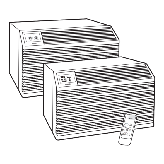
Page 1: Service Manual
Service Manual Models 2009 WallMaster Thru-the-Wall ® 2008 WM-ServMan (04-09) - Page 2 TECHNICAL SUPPORT CONTACT INFORMATION FRIEDRICH AIR CONDITIONING CO. Post Office Box 1540 · San Antonio, Texas 78295-1540 4200 N. Pan Am Expressway · San Antonio, Texas 78218-5212 (210) 357-4400 · FAX (210) 357-4490 www.friedrich.com Printed in the U.S.A.
-
Page 3: Table Of Contents
Table Of Contents Important Safety Information ........................2-4 Introduction ..............................4 WallMaster Model Number Code and Serial Number Identification ............5 Performance Data / Sleeve and Chassis Dimensions .................6 Electrical Data ..............................7 Functional Components ..........................8 How to Operate the Electronic WallMaster Room Air Conditioner ............9-10 Remote Control ............................11 Electronic Control: Operation, Testing, Error Codes, Rebooting ............12-13 How to Operate the WallMaster with Rotary Controls, Control Testing ............14... -
Page 4: Important Safety Information
IMPORTANT SAFETY INFORMATION The information contained in this manual is intended for use by a qualified service technician who is familiar with the safety procedures required for installation and repair, and who is equipped with the proper tools and test instruments required to service this product. Installation or repairs made by unqualified persons can result in subjecting the unqualified person making such repairs as well as the persons being served by the equipment to hazards resulting in injury or electrical shock which can be serious or even fatal. - Page 5 • Do not spray or pour water on the return air grille, discharge air grille, evaporator coil, control panel, and sleeve on the room side of the air conditioning unit while cleaning. • Electrical component malfunction caused by water could result in electric shock or other electrically unsafe conditions when the power is restored and the unit is turned on, even after the exterior is dry.
-
Page 6: Introduction
PROPERTY DAMAGE HAZARDS FIRE DAMAGE HAZARDS: • Read the Installation/Operation Manual for this air conditioning unit prior to operating. • Use air conditioner on a single dedicated circuit within the specified amperage rating. • Connect to a properly grounded outlet only. •... -
Page 7: Wallmaster Model Number Code And Serial Number Identification
FRIEDRICH wAllMASTER MODEl NUMBER CODE 1st DIGIT - FUNCTION W = Thru-The-Wall, WallMaster Series 2nd DIGIT - TYPE S = Straight Cool E = Electric Heat Y = Heat Pump 3rd & 4th DIGITS - APPROXIMATE BTU/HR (Cooling) Heating BTU/HR capacity listed in Specifications/Performance Data Section... -
Page 8: Performance Data / Sleeve And Chassis Dimensions
2008 / 2009 PERFORMANCE DATA EVAPORATOR AIR EVAPORATOR TEMP. OPERATING BREAKER ELECTRICAL RATINGS R-22 REF. TEMP. DEG. F DEG. F PRESSURES FUSE COOLING CONDENSER Discharge Suction Liquid Sub- Evap Motor PERFORMANCE TEMPERATURE Super Heat Temp Temp Temp Cooling Discharge Temp. Locked Rotor Charge in 60 Hertz... -
Page 9: Electrical Data
ElECTRICAl DATA WARNING ELECTRIC SHOCK HAZARD Turn off electric power before service or installation. All electrical connections and wiring MUST be installed by a qualified electrician and conform to the National Electrical Code and all local codes which have jurisdiction. Failure to do so can result in personal injury or death. -
Page 10: Functional Components
FUNCTIONAL COMPONENTS A. Mechanical components Drain pan valve Temperature-sensitive valve that opens up to drain off condensate water when the outside temperature falls below 40°F and closes when the outside temperature reaches 60°F Plenum assembly y Diffuser with directional louvers used to direct the conditioned airflow. Blower wheel Attaches to the indoor side of the fan motor shaft and is used for distributing unconditioned, room side air though the heat exchanger and delivering conditioned air into the room. -
Page 11: How To Operate The Electronic Wallmaster Room Air Conditioner
How to operate the Friedrich WallMaster Power Cool Smart Mode Speed Fan Only Heat Clock Money Timer Start Time Saver On/Off Stop Time Temp/Hour 11 12 Figure 1: WS Model cool-only control panel Figure 2: WY/WE Model heat-cool control panel To start unit WARMER –... -
Page 12: To Set The Timer
To set the timer NOTE: Set the HOUR CLOCK (Set Hour) before attempting to set NOTE: If the unit is unplugged or the power is interrupted, the HOUR must be reset or the Timer On/Off will not function when desired. timer functions. -
Page 13: Remote Control
Figure 3: WY/WE heat-cool model remote control Figure 4: WS Models Only Additional RC1 wireless remote controls can be purchased from your Friedrich dealer. Additional RC1 wireless remote controls can be purchased from your Friedrich dealer. Using the remote control... -
Page 14: Electronic Control: Operation, Testing, Error Codes, Rebooting
ElECTRONIC CONTROl PANEl Figure 5: “WS” Cooling only models Figure 6: “WE”/”WY” heat/cool models Electronic Control Panel Electronic Control Panel Power Cool Money Saver ® Speed Mode Fan Only Clock Timer Start Time On/Off Hour Stop Time Temp/Hour TESTING THE ELECTRONIC CONTROL CHECKING ROOM TEMPERATURE The LEDs for Set/Hour: “Start Time”... - Page 15 ERROR CODES lISTING FOR “wS” MODElS SHORT CYCLE SITUATION: Defined as a FROST PROBE SHORT: Normal operation is compressor that starts and stops more frequently allowed. Replace probe. than it should. INDOOR PROBE OPEN: Control assumes KEYBOARD STUCK ERROR: If any key button indoor ambient temperature is 90 degrees F and is stuck or pressed for 20 seconds or more, the unit will operate.
-
Page 16: How To Operate The Wallmaster With Rotary Controls, Control Testing
Figure 7: System Control Panel FOR UNITS WITH ROTARY CONTROLS SYSTEM CONTROL SWITCH (“WE” & “WY” Models) An eight position switch is used to regulate the operation of the fan motor, compressor and electric heater. The unit can be operated in cooling or heating mode with operating on low, medium or high speed. -
Page 17: Electronic Control Heat Pump Operation
ElECTRONIC CONTROl OPERATION Figure 9 : Thermostat Heat Pump w/back up Electric Heat If the indoor ambient air themister reads 55 degrees, turn off the compressor and turn on the electric heat and continue fan operation until temp setting is satisfied. Then revert to standard heat pump operation. -
Page 18: Capacitor Connections
CAPACITORS DEFROST THERMOSTAT WARNING (“WY” Electromechanical Control Models Only) ELECTRIC SHOCK HAZARD This thermostat is a single pole - double throw with con- Turn off electric power before servicing. tacts between terminal “2” and “3” closing on temperature Discharge capacitor with a 20,000 Ohm 2 Watt rise and contacts between terminals “2”... -
Page 19: Heating Element
HEATING ELEMENT (“WE” &”WY” Electronic and Electromechanical Models) All “WE” and “WY” models are equipped with a 3.3 KW heating element. The heating element has two heater limit switches (bimetal thermostats) connected in series with it. The number 1 limit located near the bottom, will open the circuit when the temperature reaches 130°F +/-5°. -
Page 20: Refrigeration System Sequence Of Operation
REFRIGERATION SYSTEM SEQUENCE OF OPERATION A good understanding of the basic operation of the The refrigerant leaves the condenser Coil through the liquid refrigeration system is essential for the service technician. line as a warm high pressure liquid. It next will pass through Without this understanding, accurate troubleshooting of the refrigerant drier (if so equipped). -
Page 21: Sealed System Refrigeration Repairs / Charging
SEAlED REFRIGERATION SYSTEM REPAIRS IMPORTANT ANY SEALED SYSTEM REPAIRS TO COOL-ONLY MODELS REQUIRE THE INSTALLATION OF A LIQUID LINE DRIER. ALSO, ANY SEALED SYSTEM REPAIRS TO HEAT PUMP MODELS REQUIRE THE INSTALLATION OF A SUCTION LINE DRIER. EQUIPMENT REQUIRED: High Pressure Gauge - (0 - 400 lbs.) 1. - Page 22 Method Of Charging / Repairs The acceptable method for charging the WallMaster system is the Weighed in Charge Method. The weighed in charge method is applicable to all units. It is the preferred method to use, as it is the most accurate. The weighed in method should always be used whenever a charge is removed from a unit such as for a leak repair, compressor replacement, or when there is no refrigerant...
-
Page 23: Undercharged Refrigerant Systems
WARNING WARNING HIGH PRESSURE HAZARD ELECTRIC SHOCK HAZARD Turn off electric power before service or Sealed Refrigeration System contains refrigerant installation. and oil under high pressure. Extreme care must be used, if it becomes Proper safety procedures must be followed, necessary to work on equipment with power and proper protective clothing must be worn applied. -
Page 24: Restricted Refrigerant System
Restricted Refrigerant System Troubleshooting a restricted refrigerant system can be at the metering device entrance to the evaporator. The difficult. The following procedures are the more common evaporator in a partial restriction could be partially frosted problems and solutions to these problems. There are two or have an ice ball close to the entrance of the metering types of refrigerant restrictions: Partial restrictions and device. -
Page 25: Hermetic Components Check
HERMETIC COMPONENTS CHECK WARNING WARNING BURN HAZARD Proper safety procedures must be followed, CUT/SEVER HAZARD and proper protective clothing must be worn Be careful with the sharp edges and corners. when working with a torch. Wear protective clothing and gloves, etc. Failure to follow these procedures could Failure to do so could result in serious injury. -
Page 26: Reversing Valve Description/Operation
REVERSING VAlVE DESCRIPTION/OPERATION WARNING ELECTRIC SHOCK HAZARD Disconnect power to the unit before servicing. Failure to follow this warning could result in serious injury or death. The Reversing Valve controls the direction of refrigerant “A” and “B” ports of the pilot valve. A third capillary is a common flow to the indoor and outdoor coils. -
Page 27: Testing The Coil And Reversing Valve
TESTING THE COIl pressure to build in the system. Then switch the system WARNING from heating to cooling. ELECTRIC SHOCK HAZARD If the valve is stuck in the heating position, block the air Unplug and/or disconnect all electrical power flow through the indoor coil and allow discharge pressure to the unit before performing inspections, to build in the system. -
Page 28: Procedure For Changing Reversing Valve
Touch Test in Heating/Cooling Cycle 6. Protect new valve body from heat while brazing with plastic WARNING heat sink (Thermo Trap) or wrap valve body with wet rag. BURN HAZARD Certain unit components operate at Fit all lines into new valve and braze lines into new temperatures hot enough to cause burns. -
Page 29: Compressor Checks
COMPRESSOR CHECKS External Overload WARNING The compressor is equipped with an external overload which senses both motor amperage and winding tem- ELECTRIC SHOCK HAZARD perature. High motor temperature or amperage heats the Turn off electric power before service or installation. Extreme care must be used, if it overload causing it to open, breaking the common circuit becomes necessary to work on equipment with within the compressor. -
Page 30: Single Phase Resistance Test
Single Phase Resistance Test Many compressor failures are caused by the following WARNING conditions: Improper air flow over the evaporator. ELECTRIC SHOCK HAZARD Turn off electric power before service or Overcharged refrigerant system causing liquid to be installation. Extreme care must be used, if it returned to the compressor. -
Page 31: Compressor Replacement
COMPRESSOR REPlACEMENT Recommended procedure for compressor After all refrigerant has been recovered, disconnect suction and discharge lines from the compressor and replacement remove compressor. Be certain to have both suction WARNING and discharge process tubes open to atmosphere. Carefully pour a small amount of oil from the suction RISK OF ELECTRIC SHOCK Unplug and/or disconnect all electrical power stub of the defective compressor into a clean... - Page 32 SPECIAL PROCEDURE IN THE CASE OF MOTOR COMPRESSOR BURNOUT WARNING ELECTRIC SHOCK HAZARD Turn off electric power before service or installation. Failure to do so may result in personal injury, or death. WARNING HIGH PRESSURE HAZARD Sealed Refrigeration System contains refrigerant and oil under high pressure.
-
Page 33: Routine Maintenance
ROUTINE MAINTENANCE NOTICE WARNING Units are to be inspected and serviced by qualified service ELECTRIC SHOCK HAZARD personnel only. Use proper protection on surrounding Turn off electric power before inspections, property. Failure to follow this notice could result in maintenances, or service. moderate or serious property damage. - Page 34 ROUTINE MAINTENANCE (Continued) NOTICE Do not drill holes in the bottom of the drain pan or the underside of the unit. Not following this notice could result in damage to the unit or condensate water leaking inappropriately which could cause water damage to surrounding property.
-
Page 35: General Troubleshooting
COOlING ONlY ROOM AIR CONDITIONERS: TROUBlESHOOTING TIPS Check voltage at compressor. 115V & 230V Low voltage units will operate at 10% voltage variance T-stat not set cold enough or Set t-stat to coldest position. Test t-stat & re- inoperative place if inoperative Compressor hums but cuts off on Hard start compressor. -
Page 36: Wiring Diagrams
Replace fuse, reset breaker. If repeats, check Fuse blown or circuit tripped fuse or breaker size. Check for shorts in unit wiring & components Power cord not plugged in Plug it in System switch in “OFF” position Set switch correctly Unit does not run Inoperative system switch or open Test for continuity... - Page 37 Overload inoperative. Opens too Check operation of unit. Replace overload if soon system operation is satisfactory Allow a minimum of 2 minutes to allow Compressor restarted before pressures to equalize before attempting to system pressures equalized restart. Instruct customer of waiting period Check voltage with unit operating.
- Page 38 Problem Possible Cause Action Sublimation: Ensure that foam gaskets are installed in When unconditioned saturated, between window panes & in between the outside air mixes with conditioned unit & the sleeve. Also, ensure that fresh air, condensation forms on the air/exhaust vents (on applicable models) are in cooler surfaces the closed position &...
- Page 39 HEAT PUMP TROUBlESHOOTING Problem Possible Cause Action Disconnect power to unit. Remove resistor Heat anticipator (resistor) shorted from t-stat bulb block. Plus in unit & allow to (on applicable models) operate. Feel resistor for heat. If not heat, replace resistor Room Wide differential - partial loss of temperature...
- Page 40 HEAT PUMP TROUBlESHOOTING Incorrect wiring Refer to applicable wiring diagram Defective solenoid coil Check for continuity of coil Block condenser coil & switch unit to cooling. Allow pressure to build up in system, then Unit cools when Reversing valve fails to shift switch to heating.
- Page 41 TROUBlESHOOTING TOUCH TEST CHART: TO SERVICE REVERSING VAlVES NORMAL FUNCTION OF VALVE NOTES: VALVE OPERATING * TEMPERATURE OF VALVE BODY CONDITION ** WARMER THAN VALVE BODY POSSIBLE CAUSES CORRECTIONS Cool Normal Cooling Cool *TVB as (2) as (1) Cool Normal Heating Cool *TVB as (1)
- Page 42 wAllMASTER wIRING DIAGRAM ElECTRONIC CONTROl COOl ONlY MODElS: wS08B10A-D,A-F wS10BIOA-D wS14B10A-D wS14B10A-E wS10B30A-D wS13B30B-E,B-F wS16B30A-D,A-E...
- Page 43 wAllMASTER wIRING DIAGRAM ElECTRONIC CONTROl COOl wITH ElECTRIC HEAT MODElS: wE10B33C-A wE13B33C-A wE16B33C-A...
- Page 44 wAllMASTER wIRING DIAGRAM ElECTRONIC CONTROl HEAT PUMP wITH ElECTRIC HEAT MODElS: wY10B33C-A wY13B33C-A...
- Page 45 wAllMASTER wIRING DIAGRAM ElECTROMECHANICAl CONTROl COOl wITH ElECTRIC HEAT MODElS: wE10B33A-C wE13B33B-D,B-E wE16B33A-C,A-D...
- Page 46 wAllMASTER wIRING DIAGRAM ElECTROMECHANICAl CONTROl HEAT PUMP wITH ElECTRIC HEAT MODElS: wY10B33A-C,A-D wY13B33A-C,A-D...
-
Page 47: Installation Accessories
Installation Accessories DK / Drain Kit SB / Sub Base IDK / Internal Drain Kit Installed at the back of the unit and allows Used as a base for the unit when New construction applications where Necessary when installing in a sleeve for attachment to permanent condensate it is desired to place the cord and a condensate drain system has been... -
Page 48: Installation Instructions For "Wsc" Sleeve
INSTALLATION INSTRUCTIONS FOR “WSC” SLEEVE MOUNTING HARDWARE PROVIDED ITEM DESCRIPTION QTY. SCREW, #12A X 2” WALL PREPARATION: STEP 1 The wall opening required for a “WSC” SLEEVE is 17 1/4” high by 27 1/4” wide. STEP 2 LINTELS must be used in opening of brick veneer and masonry walls to support the material above the “WSC” SLEEVE. -
Page 49: Installation Requirements
For immediate installation of sleeve and chassis (skip if installing chassis into sleeve at a later date): Remove the rear WEATHER PANEL. Reverse grille and place lower edge into sleeve tab (Friedrich logo facing out). Align slots with screw holes. Secure grille with screws. -
Page 50: Installation Instructions For Baffle Adapter Kit
WARNING MECHANICAL HAZARD CUT/SEVER HAZARD Be careful with the sharp edges and corners. Wear protective clothing and gloves, etc. Failure to do so could result in serious injury. -
Page 51: Seal Gasket Installation Instructions
SEALING GASKET INSTALLATION INSTRUCTIONS WARNING WARNING MECHANICAL HAZARD MECHANICAL HAZARD CUT/SEVER HAZARD Sharp edges and corners. Be careful with Be careful with the sharp edges and corners. the sharp edges and corner. Wear protective Wear protective clothing and gloves, etc. clothing and gloves, etc. -
Page 52: Installation Instructions For Internal Drain Kit (Idk)
INSTALLATION INSTRUCTIONS FOR INTERNAL DRAIN KIT (IDK) Apply Sealer to the bottom of the Drain Plate Wall Sleeve Drill a .625” diameter 0.5” In hole here from edge Sleeve Base 4.75” From back of Drill a .625” basepan diameter hole in the bottom of Dimple the basepan... -
Page 53: Assembly And Installation Instructions For Drain Kit (Dk)
WARNING WARNING MECHANICAL HAZARD EXCESSIVE WEIGHT HAZARD CUT/SEVER HAZARD Use two people to lift or carry the unit, Be careful with the sharp edges and corners. and wear proper protective clothing. Wear protective clothing and gloves, etc. Failure to do so may result in serious Failure to do so could result in serious injury. -
Page 54: Installation Instructions For Sub-Base
WARNING MECHANICAL HAZARD CUT/SEVER HAZARD Be careful with the sharp edges and corners. Wear protective clothing and gloves, etc. Failure to do so could result in serious injury. -
Page 55: Installation Instructions For Architectural Grille Model Ag-48-49
WARNING MECHANICAL HAZARD CUT/SEVER HAZARD Be careful with the sharp edges and corners. Wear protective clothing and gloves, etc. Failure to do so could result in serious injury. - Page 56 WARNING MECHANICAL HAZARD CUT/SEVER HAZARD Be careful with the sharp edges and corners. Wear protective clothing and gloves, etc. Failure to do so could result in serious injury.
-
Page 57: Warranty
FIRST YEAR ANY PART: If any part supplied by FRIEDRICH fails because of a defect in workmanship or material within twelve months from date of original purchase, FRIEDRICH will repair the product at no charge, provided room air conditioner is reasonably accessible for service. - Page 59 TECHNICAL SUPPORT CONTACT INFORMATION FRIEDRICH AIR CONDITIONING CO. Post Office Box 1540 · San Antonio, Texas 78295-1540 4200 N. Pan Am Expressway · San Antonio, Texas 78218-5212 (210) 357-4400 · FAX (210) 357-4490 www.friedrich.com Printed in the U.S.A.
- Page 60 FRIEDRICH AIR CONDITIONING CO. Post Office Box 1540 · San Antonio, Texas 78295-1540 4200 N. Pan Am Expressway · San Antonio, Texas 78218-5212 (210) 357-4400 · FAX (210) 357-4490 www.friedrich.com WM-ServMan (04-09) Printed in the U.S.A.
Need help?
Do you have a question about the WallMaster 2009 and is the answer not in the manual?
Questions and answers