Friedrich WallMaster WE10B33A Service And Parts Manual
Thru-the-wall
Hide thumbs
Also See for WallMaster WE10B33A:
- Installation and operation manual (56 pages) ,
- Service & parts manual (41 pages)

Related Manuals for Friedrich WallMaster WE10B33A


Summary of Contents for Friedrich WallMaster WE10B33A
- Page 1 Service & Parts Manual ® WallMaster Thru-the-Wall WM-Svc-Prts-06 (7-06) WS08B10A-B WS10B10A-B WS14B10A-B WS10B30A-B WS13B30B WS16B30A-B WE10B33A-B WE13B33B WE16B33A-B WY10B33A-B WY13B33A-B...
-
Page 2: Table Of Contents
TABLE OF CONTENTS Warranty ...3 Routine Maintenance ...4 Unit Identifi cation ...5 Performance Data ...6 Electrical Data ...7 Functional Component Defi nitions ...8 Electronic Controls ...9 Rotary Controls ...10 Refrigeration Sequence of Operation ...11 Sealed Refrigeration Repairs ... 12-13 Refrigerant Charging ...13 General Troubleshooting ... -
Page 3: Warranty
THRU-THE-WALL AIR CONDITIONERS ANY PART: If any part supplied by FRIEDRICH fails because of a defect in workmanship or material within twelve months from date of original purchase, FRIEDRICH will repair the product at no charge, provided room air conditioner is reasonably accessible for service. -
Page 4: Routine Maintenance
NOTE: Units are to be inspected and serviced by qualifi ed service personnel only. Routine maintenance is required annually or semi-annually, depending upon annual usage. Clean the unit air intake fi lter at least every 250 to 300 fan hours of operation or when the unit’s indicator light is on if so equipped. -
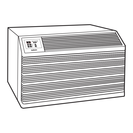
Page 5: Unit Identifi Cation
FRIEDRICH ROOM MODEL NUMBER CODE 1st DIGIT - FUNCTION W = Thru-The-Wall, WallMaster Series 2nd DIGIT - TYPE S = Straight Cool E = Electric Heat Y = Heat Pump 3rd & 4th DIGITS - APPROXIMATE BTU/HR (Cooling) Heating BTU/HR capacity listed in Specifi cations/Performance Data Section... -
Page 6: Performance Data
PERFORMANCE DATA * Rating Conditions: 80 degrees F, room air temp. & 50% relative humidity, with 95 degree F, outside air temp & 40% relative humidity Calculate the heat loss of the space to be heated. As long as the heat loss does not exceed the resistance heating capacity rating of the unit, the heating performance will be satisfactory. Change-over from heat pump operation to resistance operation on models indicated is automatic at a preset outside ambient temperature of approximately 35°F. -
Page 7: Electrical Data
The consumer - through the AHAM Room Air Conditioner Certifi cation Program - can be certain that the AHAM Certifi cation Seal accurately states the unit’s cooling and heating capacity rating, the amperes and the energy effi... -
Page 8: Functional Component Defi Nitions
FUNCTIONAL COMPONENTS A. Mechanical components Bellows condensate valve Temperature-sensitive valve that opens up to drain off condensate water when the outside temperature falls below 40°F and closes when the outside temperature reaches 58°F. Plenum assembly Diffuser with directional louvers used to direct the conditioned airfl ow. Blower wheel Attaches to the indoor side of the fan motor shaft and is used for distributing unconditioned, room side air though the heat exchanger and delivering conditioned air into the room. -
Page 9: Electronic Controls
SYSTEM CONTROL PANEL (“WS” Models) Figure 6: System Control Panel Cool Money Saver ® Speed Mode Fan Only Clock Timer Start Time Hour On/Off Stop Time TESTING THE ELECTRONIC CONTROL CHECKING ROOM TEMPERATURE 1. Check the room temperature at the electronic control pad by pressing at the same time the “FAN SPEED”... -
Page 10: Rotary Controls
Frost Probe Sensor: Disables compressor at 35 degrees F +/- 3 degrees F Indoor Probe Sensor: Control range is 60 degrees F to 90 degrees F +/- 2 degrees F Indoor temperature will be displayed by pressing: (XQ / WS Units) The Fan Speed button and the Temp Up button. -
Page 11: Refrigeration System Sequence Of Operation
REFRIGERATION SYSTEM SEQUENCE OF OPERATION A good understanding of the basic operation of the refrigera- tion system is essential for the service technician. Without this understanding, accurate troubleshooting of refrigeration system problems will be more diffi cult and time consuming, if not (in some cases) entirely impossible. -
Page 12: Sealed Refrigeration Repairs
SEALED REFRIGERATION SYSTEM REPAIRS EQUIPMENT REQUIRED: 1. Voltmeter 2. Ammeter 3. Ohmmeter 4. Vacuum Pump (capable of 200 microns or less vacuum.) 5. Acetylene Welder 6. Electronic Halogen Leak Detector (G.E. Type H-6 or equivalent.) 7. Accurate refrigerant charge measuring device such a. -
Page 13: Refrigerant Charging
The introduction of liquid into the low side, without the use of a capillary tube, will cause damage to the discharge valve of the rotary compressor. NOTE: All inoperative compressors returned to Friedrich must have all lines properly plugged with the plugs from the replacement compressor. -
Page 14: General Troubleshooting
VALVE OPERATING CONDITION Normal Cooling Cool as (2) Normal Heating Cool as (1) Check Electrical circuit and coil Check refrigeration charge Cool Cool, Valve will not as (2) shift from cool to heat. Cool, Cool as (2) Valve will not Cool, shift from cool Cool... - Page 15 COOLING ONLY ROOM AIR CONDITIONERS: TROUBLESHOOTING TIPS Problem Possible Cause Low voltage T-stat not set cold enough or inoperative Compressor hums but cuts off on B10 overload Compressor Open or shorted compressor does not run windings Open overload Open capacitor Inoperative system switch Broken, loose or incorrect wiring Problem...
-
Page 16: Wiring Diagrams
Problem Fuse blown or circuit tripped Power cord not plugged in Unit does not run System switch in "OFF" position Inoperative system switch Loose or disconnected wiring at switch or other components Problem Dirty fi lter Restricted airfl ow Inoperative t-stat Evaporator coil freezes up Short of refrigerant... - Page 17 Instruct customer of waiting period Check voltage with unit operating. Check for other appliances on circuit. Air conditioner should be in separate circuit for proper voltage & fused separately Refer to appropriate wiring diagram...
- Page 18 Problem Sublimation: When unconditioned saturated, outside air mixes with conditioned air, condensation forms on the cooler surfaces Water "spitting" into room Downward pitch of installation is too steep Restricted coil or dirty fi lter Problem Insuffi cient air circulation thru area to be air conditioned Oversized unit Excessive moisture...
- Page 19 HEAT / COOL ROOM AIR CONDITIONERS: TROUBLESHOOTING TIPS Problem Possible Cause Heat anticipator (resistor) shorted (on applicable models) Room temperature uneven Wide differential - partial loss of (Heating cycle) t-stat bulb charge Incorrect wiring Problem Possible Cause Incorrect wiring Defrost control timer motor not advancing (applicable models) Defrost control out of calibration (applicable models)
- Page 20 Problem Incorrect wiring Defective solenoid coil Unit cools when heat is called for Reversing valve fails to shift Inoperative system switch Problem Heating capillary tube partially restricted Cooling adequate, Check valve leaking internally but heating insuffi cient Reversing valve failing to shift completely;...
- Page 21 WIRING DIAGRAM: MODELS WS08B10A-B, WS10B10A-B, WS14B10A-B, WS10B30A-B, WS13B30B...
- Page 22 WIRING DIAGRAM: MODELS WS16B30A-B...
- Page 23 WIRING DIAGRAM: MODELS WE10B33A-B, WE13B33B...
- Page 24 WIRING DIAGRAM: MODELS WE16B33A-B...
- Page 25 WIRING DIAGRAM: MODELS WY10B33A-B, WY13B33A-B...
-
Page 26: Parts Diagram
WS, WE & WY SERIES CHASSIS PARTS... -
Page 27: Parts Lists
DESCRIPTION PART NO# ELECTRICAL PARTS ELECTRONIC BOARD 61921188 ELECTRONIC BOARD 61921189 REMOTE CONTROL 61826605 THERMOSTAT 25043302 THERMOSTAT, DEF. 61350313 OVERLOAD 61764507 OVERLOAD 61764519 OVERLOAD 61764528 OVERLOAD 61764554 OVERLOAD 61764555 OVERLOAD 61764556 CAPACITOR 61080533 CAPACITOR 61080569 CAPACITOR 61080535 CAPACITOR 61080540 CAPACITOR 61080526 CAPACITOR 61080537... - Page 28 HARDWARE, SCREWS 60846020 GASKET, CHASSIS 61717301 CARTON, SHIPPING 61841911 START KIT 61008903 SERV.& PART MANUAL SLEEVE (ONLY) 61603601 GRILLE, STAMPED 61603001 FRIEDRICH SCRIPT 61823504 * Not Shown WALLMASTER PARTS OPTIONAL ACCESSORIES ITEMS WM05 230V 230V 230V 230V 230V 230V 230V...
- Page 29 “WS” - “WE” - “WY” SERIES SLEEVE PARTS REF. PART NO. 616-036-01 Sleeve Assembly ... 616-032-00 Panel, Weather Inner ... 616-030-01 Grille, Louvered ... 616-033-01 Panel, Weather Outer ... * Not Shown DESCRIPTION CHASSIS PARTS, (Cont.) WS, WE & WY SERIES SLEEVE PARTS APPLICATION...
- Page 30 Friedrich Air Conditioning Co. Post Office Box 1540 • San Antonio, Texas 78295-1540 4200 N. Pan Am Expressway • San Antonio, Texas 78218-5212 (210) 357-4400 • FAX (210) 357-4480 www.friedrich.com Printed in the U.S.A. WM-Svc-Prts-06 (7-06)
Need help?
Do you have a question about the WallMaster WE10B33A and is the answer not in the manual?
Questions and answers
my wallmaster air conditioner menu will not display unit works fine and cools fine menu display will not light up i tried resetting and still does not display