Table of Contents
Advertisement
Advertisement
Table of Contents
Troubleshooting

Related Manuals for SATO LM408


Summary of Contents for SATO LM408
- Page 1 LM408/412e PRINTER OPERATOR MANUAL PN: 9001155A...
- Page 2 SATO America, Inc. 10350A Nations Ford Road Charlotte, NC 28273 Main Phone: (704) 644.1650 Technical Support Hotline: (704) 644.1660 Technical Support Fax: (704) 644.1661 E-Mail: satosales@satoamerica.com techsupport@satoamerica.com www.satoamerica.com WARNING THE EQUIPMENT REFERENCED IN THIS DOCUMENT COMPLIES WITH THE REQUIREMENTS IN PART 15 OF FCC RULES FOR A CLASS B COMPUTING DEVICE.
-
Page 3: Table Of Contents
Continuous Mode Interface Selection RS232C High-Speed Serial Interface IEEE1284 Parallel Interface 3-10 Universal Serial BUS (USB) Adapter 3-11 Local Area Network (LAN) Ethernet 3-11 802.11G Wireless 3-11 All Interfaces 3-14 Accessories Installation 3-16 Interface Installation 3-16 LM408-412e Operator Manual PN: 9001155A... - Page 4 Error Signal Troubleshooting Troubleshooting Table Interface Troubleshooting Parallel Interface RS232 Serial Interface Universal Serial Bus (USB) Interface LAN Ethernet Interface 802.11G Wireless Interface Centronics Interface Test Print Troubleshooting Hex Dump Mode Test Label Printing Sample Test Label LM408-412e Operator Manual PN: 9001155A...
- Page 5 Ribbon Guide Label Sensor Positioning 6-10 Ribbon Spindle Tensioning 6-11 Operational Adjustments 6-12 Pitch 6-12 6-12 Offset Darkness 6-12 APPENDIX Print Setup Dimensions Label Reference Position Label Adjustment Diagram Printer Connection Diagram Printer Laoding Diagram Glossary LM408-412e Operator Manual PN: 9001155A...
-
Page 6: Introduction
INTRODUCTION • About This Manual • General Description • Control Features LM408-412e Operator Manual PN: 9001155A... - Page 7 This manual is laid out consistent with the product discussed and provides all of the information required for printer maintenance and repair by SATO approved personnel. For the repair technician, this manual is intended to compliment, and to be used as an extension of, owner/operator literature.
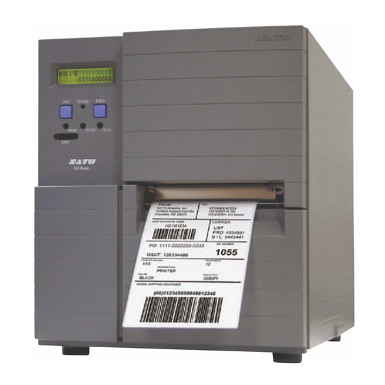
- Page 8 Unit 1: Introduction GENERAL DESCRIPT The SATO LM400e series printers have been designed as mid-range, industrial printers that are meant to meet the needs of those users that require ruggedness, but only require an entry-level industial printer. This mid-range printer is intended for applications that do not need the options and feature sets that are available and common in our standard Enhanced and Pro printers.
-
Page 9: Control Features
OFF: Enables Single-Item Interface Receive Mode (ENQ response) DSW6 Enables Download Mode feature OFF: Disables Download Mode feature DSW7 Enables Control Code feature OFF: Disables Control Code feature DSW8 Enables 203dpi Print Resolution OFF: Enables 305dpi Print Resolution LM408-412e Operator Manual PN: 9001155A... - Page 10 Unit 1: Introduction LCD Display LED Display Function Keys Potentiometers Dipswitch Complex Figure 1-2, Operator Panel LM408-412e Operator Manual PN: 9001155A...
-
Page 11: Technical Data
TECHNICAL DATA • Physical Characteristics • Power • Enviromental • Processing • Interface Modules • Print • Sensing • Media • Ribbon • Command • Regulatory Approvals • Character Font Capabilities • Barcode Capabilities LM408-412e Operator Manual PN: 9001155A... - Page 12 LM412e: 305 Dots Per Inch (12 dpmm) Maximum Print Width 4.09 Inches (104 mm) Maximum Print Length 7.01 Inches (178 mm) LM408e: 49.17 Inches (1249 mm) Pitch at EX Command LM412e: 32.80 Inches (833 mm) LM408-412e Operator Manual PN: 9001155A...
-
Page 13: Sensing
Core Diameter 1 Inch (25.6 mm) Material Polyester film Thickness (5.8 +/- 0.8 to 8.3 +/- 0.6 ym) COMMAND SATO Barcode Printer Language (SBPL) Standard Intelligent Command Non-Standard REGULATORY Safety FCC (Class B), EN 55022 (Class B) LM408-412e Operator Manual... -
Page 14: Character Font Capabilities
CG Triumvirate, 8 to 72 pt. DOWNLOADABLE FONTS CHARACTER CONTROL Expansion up to 12 x in either the X or Y coordinates. Character Pitch Control Line Space Control Journal Print Facility 0, 90, 180, and 270 Degree Rotation LM408-412e Operator Manual PN: 9001155A... - Page 15 Sequential numbering of both numerics and bar codes Expansion Ratio of Character Height: 1-12 times, Width: 1-12 times Graphics Full dot addressable graphics, SATO Hex/Binary, BMP or PCX formats Form Overlay Form overlay for high-speed editing of complex formats LM408-412e Operator Manual...
-
Page 16: Unpacking & Parts Identification
INSTALLATION • Unpacking & Parts Identification • Printer Installation • Operational Mode Selection • Interface Selection • Accessories Installation LM408-412e Operator Manual PN: 9001155A... - Page 17 Remove the plastic covers from the packed items and visually inspect for physical damage. Ensure all components are present as dictated on the Packing List. Report damaged property. Compact Disc Power Cord Packing Cushions Printer Protective Sheet Corrugated Box Figure 3-1, Unpacking & Parts Identification LM408-412e Operator Manual PN: 9001155A...
-
Page 18: Site Location
The procedure below provides instruction on typical cable connection. The same procedure will apply to others that are not mentioned, but their connectors are also performed from the printer’s rear. Host Computer Interface Cable Printer Interface Board Power Cord Power Receptacle Figure 3-2, Cable Connection LM408-412e Operator Manual PN: 9001155A... -
Page 19: Media Selection
Refer to Figures 3-3a and 3-3b for proper media routing relative to the type to be used. If that to be used is direct thermal, ignore the ribbon stock in the figures and do not load that. Figure 3-3a, Rolled Media Loading LM408-412e Operator Manual PN: 9001155A... - Page 20 Unit 3: Installation Figure 3-3b, Fan-fold Media Loading Figure 3-3c, Ribbon Loading LM408-412e Operator Manual PN: 9001155A...
-
Page 21: Operational Mode Selection
CONTINUOUS MODE TRANSMISSION SENSOR REFLECTIVE SENSOR Base Print Position TEAR-OFF MODE REFLECTIVE SENSOR TRANSMISSION SENSOR Base Print Position Base Dispense Position Base Print & Dispense Position Figure 3-4, Label Reference Position LM408-412e Operator Manual PN: 9001155A... -
Page 22: Interface Selection
Connector (Printer Side) DB-25S Male (equivalent) Cable Connector DB-25P Female (equivalent) Cable Length 5 meters or less. Signal Levels High = +5V to +12V, Low = -5V to -12V Protocol Ready/Busy, X-On/X-Off, Protocol for Driver, Status4 LM408-412e Operator Manual PN: 9001155A... -
Page 23: Signal Definition
It goes low when the printer is off-line, either manually or due to an error condition, and while printing in the single job buffer mode. It will also go low when the data in the buffer reaches the buffer near full level. LM408-412e Operator Manual PN: 9001155A... - Page 24 Bi-Directional SG (Signal Ground) NOTE: Depending on the host used, it may be required to loop CS and RS (maintaining at high-level) on the host side. For more information, refer to the host computer documentation. LM408-412e Operator Manual PN: 9001155A...
-
Page 25: Ieee1284 Parallel Interface
From Host AutoFD To Host Fault To Host Not Used Not Used Logic Gnd Not Used Frame Gnd Not Used +5V (z=24k ohm) To Host SelectIn From Host 1 Signals required for ieee 1284 mode. 3-10 LM408-412e Operator Manual PN: 9001155A... -
Page 26: Universal Serial Bus (Usb) Adapter
0.0.0.0 to 255.255.255.255 Gateway Address 0.0.0.0 to 255.255.255.255 DIPSWITCH SETTINGS SWITCH SETTING Reserved (setup prohibited). LAN board EEPROM initialization (configuration). Print configuration details on a label. Print a self-diagmosis of the board onto a label. 3-11 LM408-412e Operator Manual PN: 9001155A... -
Page 27: Software Specifications
0.0.0.0 to 255.255.255.255 Subnet Mask 0.0.0.0 to 255.255.255.255 Gateway Address 0.0.0.0 to 255.255.255.255 Communication Mode 802.11 Ad hoc, Ad hoc, Infrastructure SSID Optional alphanumeric character string (up to 32 characters) Channels 01 to 11 3-12 LM408-412e Operator Manual PN: 9001155A... - Page 28 TELNET Complies with RFC854. This operation consists of interactive menu form and enables change and reference of internal setup, and to display status. To change the setup, enter “root” user and password at the time of login. Default of root pasword is set as null (linefeed only). 3-13 LM408-412e Operator Manual PN: 9001155A...
-
Page 29: All Interfaces
HOST DIRECTION DB25 PRINTER FG (Frame Ground) Bi-Directional FG (Frame Ground) RD (Receive Data) To Host TD (Transmit Data) TD (Transmit Data) To Printer RD (Receive Data) SG (Signal Ground) Bi-Directional SG (Signal Ground) 3-14 LM408-412e Operator Manual PN: 9001155A... - Page 30 Release Of Receive Buffer Near Full Receive buffer near full can be released when the remaining free space rises to 1.95MB or when the remaining free space is available for storing 200 items in the history buffer. 3-15 LM408-412e Operator Manual PN: 9001155A...
-
Page 31: Accessories Installation
Route interface cable (1, Figure 3-7) from host computer to interface board (2). Insert interface board (2) into printer (4) and secure using two screws (3). Connect interface cable (1). Figure 3-7, Interface Installation 3-16 LM408-412e Operator Manual PN: 9001155A... -
Page 32: Printer Configuration
PRINTER CONFIGURATION • Printer Configuration • Dipswitch Setting • Configuration Modes • Menu Definition Tables LM408-412e Operator Manual PN: 9001155A... - Page 33 The printer may be configured via the buttons and/or potentiometers loacated on the printer’s operator panel. All of the printer’s buttons, switches, and potentiometers are used either singularly, or in conjunction, to perform configuration activities. Refer to the Control Features chapter of the Introduction unit for identification of specific interface features. LM408-412e Operator Manual PN: 9001155A...
-
Page 34: Dipswitch Settings
Enable Multi-Buffer Interface Receive Mode (periodic response) Enable Single-Buffer Interface Receive Mode (ENQ response) Enable Download Mode Feature Disable Download Mode Feature Enable Control Code Feature Disable Control Code Feature Enable 203dpi Print Resolution Enable 305dpi Print Resolution LM408-412e Operator Manual PN: 9001155A... -
Page 35: Configuration Modes
Scrolls LINE options FEED PRINT SPEED Scrolls LINE options FEED PITCH OFFSET +00MM Scrolls LINE options Selects FEED advances CANCEL PRINT JOB Scrolls LINE options FEED FEED CANCEL PRINT JOB COMPLETED Figure 4-1, Normal Mode LM408-412e Operator Manual PN: 9001155A... -
Page 36: Advanced Mode
FEED FEED IGNORE CR/LF CALENDAR 00 / 00 / 00 00:00 Scrolls LINE options Scrolls FEED LINE options FEED CHARACTER PITCH PROP FIXED Selects Scrolls LINE options advances FEED Figure 4-2, Advanced Mode LM408-412e Operator Manual PN: 9001155A... -
Page 37: User Download Mode
USER DOWNLOAD PRESS LINE KEY No action, LINE FEED no change USER DOWNLOAD WAITING Send data from host system Printer receives data DOWNLOAD COMPLETE Power printer off, reset DSW7 to exit Figure 4-3, User Download Mode LM408-412e Operator Manual PN: 9001155A... -
Page 38: Service Mode
ACK SIGNAL XX.X IEEE1284 for 1 item FORWARD / BACKFEED DISTANCE DEFAULT Scrolls options LINE FEED BACKFEED SPEED NORMAL SLOW FORWARD / BACKFEED Scrolls DISTANCE XXXMM LINE options FEED Scroll LINE distance Figure 4-4, Service Mode LM408-412e Operator Manual PN: 9001155A... -
Page 39: Card Mode
CARD MODE Enters Service LINE FEED Mode MEMORY FORMAT Scrolls LINE options FEED FEED FORMAT START Scrolls LINE options FEED FEED MEMORY FORMAT FORMATTING Formatting in process MEMORY FORMAT COMPLETED FEED Figure 4-5, Card Mode LM408-412e Operator Manual PN: 9001155A... -
Page 40: Move Mode
Enters Service FEED LINE Mode COUNTERS MODE Enters Counters FEED LINE Mode MOVE MODE FEED LINE MOVE MODE CONT TEAR Scrolls LINE options Cont Tear FEED FEED PITCH SENSOR LINE FEED Figure 4-6, Motion Mode LM408-412e Operator Manual PN: 9001155A... -
Page 41: History Control Mode
Tables in the following chapter to provide an explanation of each menu screen. DSW4: ON LINE + POWER HISTORY CONTROL Scrolls LINE options FEED HISTORY CONTROL COMPLETED Power printer off, reset DSW4 to exit Figure 4-7, History Control Mode 4-10 LM408-412e Operator Manual PN: 9001155A... -
Page 42: Protocol Initialization Mode
Tables in the following chapter to provide an explanation of each menu screen. DSW7: ON LINE + FEED + POWER ALT. PROTOCOL DEFAULT COMPLETE Protocol code is initialized Power printer off, reset DSW7 to exit Figure 4-8, Protocol Initialization Mode 4-11 LM408-412e Operator Manual PN: 9001155A... -
Page 43: Counters Mode
COUNTERS MODE Enters Move LINE FEED Mode COUNTERS LIFE Scrolls LINE options Life FEED FEED HEAD COUNTER LIFE COUNTER XX.XM XX.XM FEED FEED HEAD COUNTER CLEAR Scrolls LINE options FEED Figure 4-9, Counters Mode 4-12 LM408-412e Operator Manual PN: 9001155A... -
Page 44: Test Print Mode
XXCM SMALL LARGE Scrolls LINE options FEED Test printing begins PRESS FEED KEY TO STOP PRINTING FEED Test printing stops Power printer off and then on again to exit Figure 4-10, Test Print Mode 4-13 LM408-412e Operator Manual PN: 9001155A... -
Page 45: Boot Download Mode
PROGRAM DOWNLOAD START > > > Download completed DOWNLOAD COMPLETE PRESS FEED KEY No action, FEED LINE no change Power printer off, reset DSW6 to exit Figure 4-11, Boot Download Mode 4-14 LM408-412e Operator Manual PN: 9001155A... -
Page 46: Flash Memory Download Mode
PROGRAM DOWNLOAD START > > > Download completed DOWNLOAD COMPLETE PRESS FEED KEY No action, FEED LINE no change Power printer off, reset DSW6 to exit Figure 4-12, Flash Memory Download Mode 4-15 LM408-412e Operator Manual PN: 9001155A... -
Page 47: Default Settings Mode
LINE + FEED + POWER DEFAULT SETTING Scrolls LINE options FEED FEED No action, no change Printer returned to default settings DEFAULT SETTING COMPLETED Power printer off and then on again to exit. Figure 4-13, Default Setting Mode 4-16 LM408-412e Operator Manual PN: 9001155A... -
Page 48: Hex Dump Mode
DSW4: ON POWER ONLINE QTY: XXXXXX Printer receives data Printer begins Hex Dump printing Power printer off, reset DSW4 to exit Figure 4-14a, Hex Dump Mode 4-17 LM408-412e Operator Manual PN: 9001155A... -
Page 49: Maintenance Mode
No action, LINE no change FEED Scrolls LINE LINE options Printer performs factory test print FEED FEED FEED FEED COUNTER ALLCLEAR EEPROM ALLCLEAR Power printer COMPLETED COMPLETED off to exit Figure 4-15, Maintenance Mode 4-18 LM408-412e Operator Manual PN: 9001155A... -
Page 50: Menu Definition Tables
This screen indicates that the received data has been deleted. Will display for 3 seconds and then the printer will shift to the ONLINE menu screen. CANCEL PRINT JOB COMPLETED 4-19 LM408-412e Operator Manual PN: 9001155A... -
Page 51: Menu Description
CR/LF stream - including graphics and 2D barcodes. This feature is primarily used to maintain compatibility with earlier models of SATO printers. This setting determines whether each printer character occupies a designated space (fixed) regardless of the character’s width, or if the character’s space is representative of its width CHARACTER PITCH (proportional). - Page 52 Allows it to be determined if the printer will feed a label when an error condition is cleared. FEED ON ERROR Allows it to be determined if the printer will print the last label in memory when the FEED key is pressed in the normal, online mode. REPRINT W/FEED 4-21 LM408-412e Operator Manual PN: 9001155A...
- Page 53 This menu screen allows the pulse width to be set if single-item buffer has been chosen. If single- item buffer has not been chosen, this setting will not have effect. IEEE1284 ACK SIGNAL XX.X Allows of the backfeed movement to be established. Two setting options are available. BACKFEED SPEED NORMAL SLOW 4-22 LM408-412e Operator Manual PN: 9001155A...
- Page 54 Is the first menu screen of the Counters Mode. The Counters Mode allows the printers various internal counters to be reset to zero or to view count in meters printed thus far. COUNTERS MODE Is only a transitional menu screen to access the Move Mode. 4-23 LM408-412e Operator Manual PN: 9001155A...
- Page 55 ALT. PROTOCOL returned to the default value. The default value is: STX (7BH), ETX (7DH), ESC (5EH), DEFAULT COMPLETE ENQ (40H), NULL (7EH), CAN (21H), Offline (5DH), EuroCode (D5H). 4-24 LM408-412e Operator Manual PN: 9001155A...
- Page 56 Is an informational screen that provides the printed the length of media since printer setup. LIFE COUNTER XX.XM Allows the determination of whether or not to reset the print head counter to zero. HEAD COUNTER CLEAR 4-25 LM408-412e Operator Manual PN: 9001155A...
- Page 57 START > > > This menu screen appears when all of the data has been received and the process is complete. Also prompts the operator on how to proceed. DOWNLOAD COMPLETE PRESS FEED KEY 4-26 LM408-412e Operator Manual PN: 9001155A...
- Page 58 QTY: XXXXXX MAINTENANCE MODE (TABLE 4-15) MENU DESCRIPTION Is the first menu screen of the Maintenance Mode and provides a prompt on the action required to proceed to the Factory Mode. MAINTENANCE MODE DIPSW2-4 ON->OFF 4-27 LM408-412e Operator Manual PN: 9001155A...
- Page 59 Allows the selection of large (10cm) or small (4cm) font print size. These are the only two options. PRINT SIZE SMALL LARGE Pressing FEED will initialize continuous test printing. Pressing FEED again will suspend printing. TEST PRINT PRESS FEED KEY 4-28 LM408-412e Operator Manual PN: 9001155A...
-
Page 60: Troubleshooting
TROUBLESHOOTING • Error Signal Troubleshooting • Troubleshooting Table • Interface Troubleshooting • Test Print Modes LM408-412e Operator Manual PN: 9001155A... - Page 61 2. Ensure proper print head is installed. DATA ERROR 1. Ensure cover is fully closed. DOWNLOAD ERROR Download Write 2. Replace cover-open sensor. WRITE ERROR 1. Ensure cover is fully closed. HEAD MISMATCH Head Mis-Match 2. Replace cover-open sensor. LM408-412e Operator Manual PN: 9001155A...
- Page 62 Ensure wiring harness connection. Replace as necessary. LCD FIELD ILLUMINATED BUT WITHOUT WORDS OR NO DISPLAY AT ALL Power supply issues. Ensure cable properly connected. Check/replace power supply. Incorrectly positioned display potentiometer. Adjust as required. LM408-412e Operator Manual PN: 9001155A...
- Page 63 Foreign material on print head and platen roller. Clean print head and rollers. Foreign material on labels. Use higher quality media. Excessive print head energy. Adjust darkness setting. Excessive print speed. Adjust print speed as required. LM408-412e Operator Manual PN: 9001155A...
-
Page 64: Parallel Interface
Click on the Device Manager tab. Ensure that the View Device By Type is checked. Scroll to SATO-USB Device and ensure that errors do not exist. Reinstall as required. Reboot the PC and the printer. Contact Microsoft technical support for further assistance as required. -
Page 65: Lan Ethernet Interface
0Ahex (carriage return and line feed) characters throughout. However, there should not be either located between the start (<ESC>A and the stop (<ESC>Z) commands. Replace the interface board with another to isolate the problem - permanently replace if defective. LM408-412e Operator Manual PN: 9001155A... -
Page 66: Test Print Troubleshooting
ASC ll format. Follow the flow chart provided below to perform this activity. DSW4: ON POWER ONLINE QTY: XXXXXX Printer receives data Printer begins Hex Dump printing Power printer off, reset DSW4 to exit Figure 6-3a, Hex Dump Mode LM408-412e Operator Manual PN: 9001155A... -
Page 67: Test Label Printing
NOTE: The only print problem that the following sample test label does not display is fading of print image from one side of the label to the other. This is the result of improper print head balance. LM408-412e Operator Manual PN: 9001155A... -
Page 68: Sample Test Label
N O N E speed and darkness. Clear line in print Compare this scale on each indicates the ribbon side to ensure the print is was wrinkled during evenly spaced vertically. printing. Figure 6-5, Sample Test Label LM408-412e Operator Manual PN: 9001155A... -
Page 69: Maintenance
MAINTENANCE • Cleaning Procedures • Replacement Procedures • Adjustment Procedures LM408-412e Operator Manual PN: 9001155A... - Page 70 Use a soft cloth and/or a pneumatic blower to remove debris from the printer. This process should be performed prior to the removal of residue. To remove residue, apply SATO Solvent or isopropryl alcohol to a clean cotton swab and gently wipe the entire surface of the print head and platen roller clean.
-
Page 71: Print Head
NOTE: Apply the print to the upper surface fo the print assembly’s print bracket and ensure the alignment pins insert into their respective slots. Secure replacement print head (4) to print assembly (3) and secure using screw (2). Restore power, reset the head counter, and test print. LM408-412e Operator Manual PN: 9001155A... - Page 72 Unit 6: Maintenance Figure 6-1a, Print Head Replacement Figure 6-1b, Print Head Replacement LM408-412e Operator Manual PN: 9001155A...
-
Page 73: Interface Board
Remove two screws (3) securing defective interface board (2) to printer (4). Insert replacement interface board (2) into printer (4) and secure using two screws (3). Connect interface cable (1). Figure 6-2, Interface Board Replacement LM408-412e Operator Manual PN: 9001155A... -
Page 74: Fuse
FUSE USAGE RESULT DESTROYED ELECTRICAL COMPONENTS AND/OR FIRE. ENSURE THE DAMAGED FUSE IS REPLACED WITH IDENTICAL PHYSICAL DIMENSIONS AMPERAGE. TO DO THIS, DUPLICATE THE INFORMATION STAMPED ON THE FUSE’S METAL CASING. Figure 6-3, Fuse Replacement LM408-412e Operator Manual PN: 9001155A... -
Page 75: Adjustment Procedures
To adjust the balance, begin test printing, slightly loosen set screw (1, Figure 6-4), and slightly move adjustment plate (2) to the right or left as necessary. Retighten set screw (1) while holding adjustment plate (2) when proper printing is achieved. Figure 6-4, Print Head Balance Adjustment LM408-412e Operator Manual PN: 9001155A... -
Page 76: Print Head Alignment
Test print a label to determine if print head (2, Figure 6-5a) is properly aligned. Repeat this procedure until proper alignment is achieved. Figure 6-5a, Print Head Alignment Figure 6-5b, Print Head Alignment LM408-412e Operator Manual PN: 9001155A... -
Page 77: Ribbon Guide
Retighten loose set screw (3) while holding ribbon guide (4) in place. Engage print head latch (2), close cover, and test print a label. Repeat steps 2 through 5 until proper adjustment is achieved. Figure 6-6, Ribbon Guide Alignment LM408-412e Operator Manual PN: 9001155A... -
Page 78: Label Sensor Positioning
Refer to Figure 9-3 in the Appendix unit of this manual for applicable dimensions. Test print a label to determine if label sensor (3) is properly aligned. Figure 6-7, Label Sensor Positioning 6-10 LM408-412e Operator Manual PN: 9001155A... -
Page 79: Ribbon Spindle Tensioning
NOTE: A complete revolution of the adjustment nut equals approximately 1 mm (100g). Likewise, a half revolution equals .5 mm (50g). Metric Scale Ribbon Boss Collar Adjustment Nut Set Screw Figure 6-8, Ribbon Spindle Tensioning 6-11 LM408-412e Operator Manual PN: 9001155A... -
Page 80: Operational Adjustments
If unable to achieve the desired setting here, the course adjustment must be reset. Adjust this potentiometer as labels are being printed. Allow two labels to be printed for each adjustment to ensure a desired setting. 6-12 LM408-412e Operator Manual PN: 9001155A... - Page 81 Unit 6: Maintenance CONTINUOUS MODE TRANSMISSION SENSOR REFLECTIVE SENSOR Base Print Position TEAR-OFF MODE REFLECTIVE SENSOR TRANSMISSION SENSOR Base Print Position Base Dispense Position Base Print & Dispense Position Figure 6-9, Print Base Reference Position 6-13 LM408-412e Operator Manual PN: 9001155A...
-
Page 82: Appendix
APPENDIX • Print Setup Dimensions • Label Reference Position Diagram • Label Adjustment Diagram • Printer Connection Diagram • Glossary LM408-412e Operator Manual PN: 9001155A... - Page 83 Unit 7: Appendix PRINT SETUP DIMENSIONS Gap 0.67 – 2.67" Eye-Mark 0.24 – 2.09" Mark, Gap, Paper-End Sensors Print Width: 4.09"/4.20" alid Area for Print Print Head Tear-Off Figure 7-1, Print Setup Dimensions LM408-412e Operator Manual PN: 9001155A...
-
Page 84: Label Reference Position
LABEL REFERENCE POSITION CONTINUOUS MODE TRANSMISSION SENSOR REFLECTIVE SENSOR Base Print Position TEAR-OFF MODE REFLECTIVE SENSOR TRANSMISSION SENSOR Base Print Position Base Dispense Position Base Print & Dispense Position Figure 7-2, Label Reference Position Diagram LM408-412e Operator Manual PN: 9001155A... -
Page 85: Label Adjustment Diagram
Unit 7: Appendix LABEL ADJUSTMENT DIAGRAM Figure 7-3a, Standard Position Figure 7-3b, Tear-Off Position LM408-412e Operator Manual PN: 9001155A... -
Page 86: Printer Connection Diagram
Unit 7: Appendix PRINTER CONNECTION DIAGRAM Host Computer Interface Cable Printer Interface Board Power Cord Power Receptacle Figure 7-4, Printer Connection Diagram LM408-412e Operator Manual PN: 9001155A... - Page 87 Unit 7: Appendix PRINTER LOADING DIAGRAM Figure 7-5a, Printer Loading Diagram Figure 7-5b, Printer Loading Diagram LM408-412e Operator Manual PN: 9001155A...
- Page 88 Unit 7: Appendix Figure 7-5c, Printer Loading Diagram LM408-412e Operator Manual PN: 9001155A...
-
Page 89: Glossary
Bolt A threaded metal rod with a flanged head that is used with a nut to hold parts together. Bore A hole in, or through something. LM408-412e Operator Manual PN: 9001155A... - Page 90 A change in course or the measurement of that change. A straight line from the outer edge of a circle, through the center, and onward to the opposite Diameter edge. Also the measurement of that distance (dimension). Dimension Any measurable distance. LM408-412e Operator Manual PN: 9001155A...
- Page 91 Print media with a mark on the paper backing between each label for the label sensor to read. Eye-Mark Media This mark is used by the printer to identify the end of the printed label so that the next up can be properly positioned for printing. 7-10 LM408-412e Operator Manual PN: 9001155A...
- Page 92 The ability to read from, and write to, an RFID tag while attached to its object. Junction A place or point of joining or crossing. Kinetic The science dealing with the motion of masses in relation to the forces acting on them. 7-11 LM408-412e Operator Manual PN: 9001155A...
- Page 93 Relative to RFID, a read/write or reprogrammable tag in credit card size. Memory Modules A read/write or reprogrammable RFID tag. In RFID, a vehicle equipped with a system for locating tagged vehicles, containers, and other Mobile Inventory Vehicle objects for the purpose of inventory control. 7-12 LM408-412e Operator Manual PN: 9001155A...
- Page 94 Primary Something first in order or importance. Print Assembly The sub-assembly of a printer that comprise the printing components. 7-13 LM408-412e Operator Manual PN: 9001155A...
- Page 95 Typically, a reader communicates with a tag, which holds digital information in a microchip. But RFID there are chipless forms of RFID tags that use material to reflect back a portion of the radio waves beamed at them. 7-14 LM408-412e Operator Manual PN: 9001155A...
- Page 96 Secondary The next to follow the primary in sequence or importance. A SATO specific mode of printer operation that can execute the program of BASIC format in SEMBL the printer. This allows the printer to be configured and operated without interfacing with an external computer or software.
- Page 97 Relative to RFID, the transmitter/receiver pair of transceiver plus the information storage Transponder mechanism attached to the object. Also referred to as Tag. Tread The act of an object making repetitive contact upon another that is in motion. 7-16 LM408-412e Operator Manual PN: 9001155A...
- Page 98 Xoff signal to stop sending data. When enough data is printed and the buffer storage becomes free, the printer sends an Xon signal to resume sending data. 7-17 LM408-412e Operator Manual PN: 9001155A...
Need help?
Do you have a question about the LM408 and is the answer not in the manual?
Questions and answers