
Subscribe to Our Youtube Channel
Related Manuals for Kramer VP-8x8A


Summary of Contents for Kramer VP-8x8A
- Page 1 Kramer Electronics, Ltd. USER MANUAL Model: VP-8x8A 8x8 VGA / UXGA / Audio Matrix Switcher...
-
Page 2: Table Of Contents
Introduction Getting Started Quick Start Overview Terminology Used in this User Manual Your VP-8x8A 8x8 VGA / UXGA / Audio Matrix Switcher Using the IR Transmitter Installing the VP-8x8A in a Rack Connecting the VP-8x8A Connecting the VP-8x8A Rear Panel... - Page 3 Kramer Protocol 2000 Figures Figure 1: VP-8x8A 8x8 VGA / UXGA / Audio Matrix Switcher – Front View Figure 2: VP-8x8A 8x8 VGA / UXGA / Audio Matrix Switcher – Rear View Figure 3: VP-8x8A 8x8 VGA / UXGA / Audio Matrix Switcher – Underside View...
- Page 4 Tables Table 1: Terminology Used in this User Manual Table 2: Front Panel VP-8x8A 8x8 VGA / UXGA / Audio Matrix Switcher Features Table 3: Rear Panel VP-8x8A 8x8 VGA / UXGA / Audio Matrix Switcher Features Table 4: VP-8x8A Underside Panel Features...
-
Page 5: Introduction
3 We recommend that you use only the power cord that is supplied with this machine 4 Download up-to-date Kramer user manuals from our Web site at http://www.kramerelectronics.com 5 The complete list of Kramer cables is on our Web site at http://www.kramerelectronics.com... -
Page 6: Quick Start
Getting Started Quick Start This quick start chart summarizes the basic setup and operation steps. KRAMER: SIMPLE CREATIVE TECHNOLOGY... -
Page 7: Overview
HDTV compatible and lets you simultaneously route any or all of the 8 inputs to any or all of the 8 outputs. In particular, the VP-8x8A 8x8 VGA / UXGA / Audio Matrix Switcher features: A video bandwidth of over 350MHz that ensures transparent... -
Page 8: Terminology Used In This User Manual
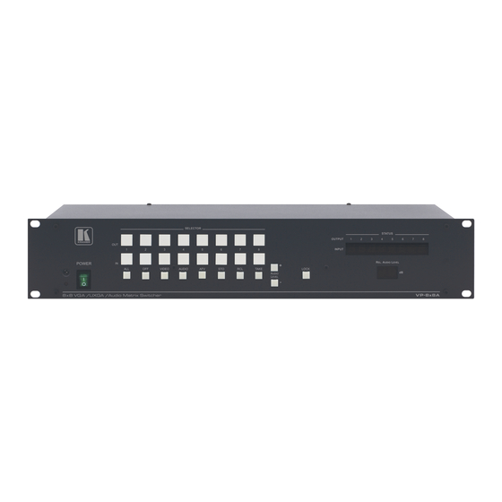
Your VP-8x8A 8x8 VGA / UXGA / Audio Matrix Switcher Figure 1, Figure 2, Table 2, and Table 3 define the VP-8x8A 8x8 VGA / UXGA / Audio Matrix Switcher. 1 The RGBHV signals are connected on 15-pin HD pin connectors to reduce enclosure size 2 Available from Kramer Electronics on our Web site at http://www.kramerelectronics.com... -
Page 10: Table 2: Front Panel Vp-8X8A 8X8 Vga / Uxga / Audio Matrix Switcher Features
Your VP-8x8A 8x8 VGA / UXGA / Audio Matrix Switcher Table 2: Front Panel VP-8x8A 8x8 VGA / UXGA / Audio Matrix Switcher Features Feature Function IR Receiver The red LED is illuminated when receiving signals from the infrared remote... -
Page 11: Figure 2: Vp-8X8A 8X8 Vga / Uxga / Audio Matrix Switcher - Rear View
Your VP-8x8A 8x8 VGA / UXGA / Audio Matrix Switcher Figure 2: VP-8x8A 8x8 VGA / UXGA / Audio Matrix Switcher – Rear View... -
Page 12: Table 3: Rear Panel Vp-8X8A 8X8 Vga / Uxga / Audio Matrix Switcher Features
Your VP-8x8A 8x8 VGA / UXGA / Audio Matrix Switcher Table 3: Rear Panel VP-8x8A 8x8 VGA / UXGA / Audio Matrix Switcher Features Feature Function Terminal Block Connect to the balanced stereo audio acceptors Connectors UnBal 3.5mm Connect to the unbalanced stereo audio acceptors... -
Page 13: Using The Ir Transmitter
Your VP-8x8A 8x8 VGA / UXGA / Audio Matrix Switcher Figure 3 illustrates the underside of the VP-8x8A unit, and Table 4 defines the underside features. Figure 3: VP-8x8A 8x8 VGA / UXGA / Audio Matrix Switcher – Underside View Table 4: VP-8x8A Underside Panel Features Feature... -
Page 14: Installing The Vp-8X8A In A Rack
Installing the VP-8x8A in a Rack Installing the VP-8x8A in a Rack This section describes what to do before installing in a rack and how to rack mount. Before Installing in a Rack How to Rack Mount Before installing in a rack, be sure that the environment is... -
Page 15: Connecting The Vp-8X8A
1 You do not need to connect all inputs and outputs 2 Switch OFF the power on each device before connecting it to your VP-8x8A. After connecting your VP-8x8A, switch on its power and then switch on the power on each device. DO NOT push in the rear panel Flash Program “FLASH PROG” button (item 8 in Table 3) and DO NOT push in the underside Flash Program “Reset”... -
Page 16: Figure 4: Connecting The Vp-8X8A 8X8 Vga / Uxga / Audio Matrix Switcher
ETHERNET (see section 6.5) 8. Connect the power cord Figure 4: Connecting the VP-8x8A 8x8 VGA / UXGA / Audio Matrix Switcher 1 We recommend that you use only the power cord that is supplied with this machine KRAMER: SIMPLE CREATIVE TECHNOLOGY... -
Page 17: Connecting The Balanced/Unbalanced Stereo Audio Input/Output
Connecting the VP-8x8A Connecting the Balanced/Unbalanced Stereo Audio Input/Output This section illustrates how to wire: A balanced input/output connection, see Figure 5 An unbalanced audio input, see Figure 6 An unbalanced audio output, see Figure 7 Figure 5: Connecting the Balanced Stereo Audio Input/Output... -
Page 18: Connecting Via Rs-232 Using A Pc
Figure 8: Connecting a PC without using a null-modem Adapter Connecting via RS-485 You can control a VP-8x8A unit via an RS-485 controller, for example, a PC (equipped with an RS-485 interface) or a Master Programmable Remote Control system such as the Kramer RC-3000. -
Page 19: Figure 9: Connecting Via Rs-485 Using An Rc-3000
Connecting the VP-8x8A 2. Use the SETUP DIP-switches to set the VP-8x8A unit to a Machine # other than 1, according to Table 7. Set the other SETUP DIP-switches on the VP-8x8A unit, as follows: Set DIP 5, DIP 6, and DIP 7 OFF... -
Page 20: Connecting Via Ethernet
6.5.2) for connection via a network hub or network router 6.5.1 Connecting the ETHERNET Port Directly to a PC (Crossover Cable) You can connect the Ethernet port of the VP-8x8A to the Ethernet port on your PC, via a crossover cable with RJ-45 connectors. -
Page 21: Figure 10: Local Area Connection Properties Window
Connecting the VP-8x8A Figure 10: Local Area Connection Properties Window 6. Select Use the following IP Address, and fill in the details as shown in Figure 11. 7. Click OK. Figure 11: Internet Protocol (TCP/IP) Properties Window... -
Page 22: Connecting The Ethernet Port Via A Network Hub (Straight-Through Cable)
Connecting the VP-8x8A 6.5.2 Connecting the ETHERNET Port via a Network Hub (Straight- Through Cable) You can connect the Ethernet port of the VP-8x8A to the Ethernet port on a network hub or network router, via a straight-through cable with RJ-45 connectors. -
Page 23: Setting The Delay
The Machine # determines the position of a VP-8x8A unit, specifying which VP-8x8A unit is being controlled when several VP-8x8A units connect to a PC or serial controller. Set the Machine # on a VP-8x8A unit via SETUP DIPS 1, 2, 3 and 4, according to Table 7. -
Page 24: Cascading Machines
Connecting the VP-8x8A Cascading Machines You can cascade up to 16 VP-8x8A units with control from a PC or serial controller. To cascade up to 16 individual VP-8x8A units via RS-485 (as illustrated in Figure 13), do the following: 1. Connect the sources and acceptors, as section 6.1 describes. -
Page 25: Figure 13: Control Configuration Via Rs-232 And Rs-485
Connecting the VP-8x8A Machine # 1 (Master) Machine # 2 Up to 16 Units Machine # 16 Figure 13: Control Configuration via RS-232 and RS-485... -
Page 26: Operating The Vp-8X8A
Perform a factory default reset 7.2.1 The Standard Reset To reset the VP-8x8A, press the IN buttons 1, 2 and 3. The machine resets but its configuration is maintained, including the stored setups, and the current configuration of the machine. -
Page 27: Understanding The 7-Segment Displays
Operating the VP-8x8A Understanding the 7-Segment Displays The VP-8x8A has two displays: The STATUS 7-segment display The REL. AUDIO LEVEL (dB) 7-segment display 7.3.1 The STATUS 7-Segment Display During normal operation, the STATUS display shows which inputs are switched to which outputs, as illustrated in Figure 14. In the VIDEO mode, the display shows the video signal setup and in the AUDIO mode, it shows the audio signal setup. -
Page 28: The Rel Audio Level 7-Segment Display
Operating the VP-8x8A firmware version and then returns to the machine default setting display (IN 1 switched to OUT 1, IN 2 switched to OUT 2, and so on). Firmware Machine Machine # version # name Figure 16: 7-segment display following Factory Default Reset 7.3.2 The REL AUDIO LEVEL 7-Segment Display... -
Page 29: Toggling Between The At Once And Confirm Modes
Operating the VP-8x8A 7.4.1 Toggling between the At Once and Confirm Modes To toggle between the At Once and Confirm modes, do the following: 1. Press the TAKE button to toggle from the At Once mode (in which the TAKE button does not illuminate) to the Confirm mode (in which the TAKE button illuminates). -
Page 30: Storing An Input/Output Configuration
2 Storing a new configuration over a previous configuration (without deleting it first) replaces the previous configuration 3 Even when the front panel is locked you can still operate via RS-232 or RS-485, as well as via the Kramer RC-IR1 Infra-... -
Page 31: Choosing The Audio-Follow-Video Or Breakaway Option
Operating the VP-8x8A To lock the VP-8x8A: Press the LOCK button for more than two seconds, until the LOCK button is illuminated The front panel is locked. Pressing a button will have no effect other than causing the LOCK button to blink... -
Page 32: The Audio Output Gain Control
L, indicating low audio value (see Figure 27, the output gain vs gain value graph). Flash Memory Upgrade The VP-8x8A firmware is located in FLASH memory, which lets you upgrade to the latest Kramer firmware version in minutes! The process involves: Downloading from the Internet (see section 8.1) -
Page 33: Downloading From The Internet
Before installing the latest Kramer firmware version on a VP-8x8A unit, do the following: 1. Connect the RS-232 9-pin D-sub rear panel port on the VP-8x8A unit to the null-modem adapter and connect the null-modem adapter with a 9-wire flat cable to the RS-232 9-pin D-sub COM port on your PC (see section 6.2). -
Page 34: Figure 19: Splash Screen
Figure 20: Atmel – Flip Window 3. Press the keyboard shortcut key F2 (or select the “Select” command from the Device menu, or press the integrated circuit icon in the upper right corner of the window). The “Device Selection” window appears: KRAMER: SIMPLE CREATIVE TECHNOLOGY... -
Page 35: Figure 21: Device Selection Window
Flash Memory Upgrade Figure 21: Device Selection Window 4. Click the button next to the name of the device and select from the list: AT89C51RD2: AT89C51RD2 T89C51RD2 Figure 22: Selecting the Device from the Selection Window 5. Click OK and select “Load Hex” from the File menu. -
Page 36: Figure 23: Loading The Hex
Figure 23: Loading the Hex 6. The Open File window opens. Select the correct HEX file that contains the updated version of the firmware for VP-8x8A (for example VP8x8AM_V1p2.hex) and click Open. 7. Press the keyboard shortcut key F3 (or select the “Communication / RS232”... -
Page 37: Figure 25: Atmel - Flip Window (Connected)
Flash Memory Upgrade Verify that in the Buffer Information column, the “HEX File: VP8x8.hex” appears. VP8x8A.hex Figure 25: Atmel – Flip Window (Connected) 9. Click Run. After each stage of the operation is completed, the check-box for that stage becomes colored green When the operation is completed, all 4 check-boxes will be colored green and the status bar message: Memory Verify Pass appears 1 See also the blue progress indicator on the status bar... -
Page 38: Figure 26: Atmel - Flip Window (Operation Completed)
10. Close the “ Atmel – Flip” window. 11. Disconnect the power on the VP-8x8A. 12. Disconnect the RS-232 rear panel port on the VP-8x8A unit from the null- modem adapter. 13. Release FLASH PROG button on rear panel (see Figure 2). -
Page 39: Technical Specifications
Technical Specifications Technical Specifications Table 8 lists the technical specifications: Table 8: Technical Specifications of the VP-8x8A 8x8 Video Audio Matrix Switcher INPUTS: 8 VGA on 15-pin HD connectors (VGA through UXGA); 8 balanced stereo audio terminal block connectors; 8 unbalanced stereo audio 3.5mm mini connectors OUTPUTS: 8 VGA on 15-pin HD connectors (VGA through UXGA);... -
Page 40: Table Of Hex Codes For Serial Communication
Table of Hex Codes for Serial Communication Table of Hex Codes for Serial Communication Table 9 lists the Hex values for a single machine (MACHINE # 1): Table 9: VP-8x8A Hex Codes for Switching via RS-232/RS-485 Switching Video Channels OUT 1... -
Page 41: Table 10: Vp-8X8A Hex Codes For Switching Audio Channels Via Rs-232/Rs-485
Table of Hex Codes for Serial Communication Table 10 lists the Hex values for switching audio channels via RS-232/RS-485: Table 10: VP-8x8A Hex Codes for Switching Audio Channels via RS-232/RS-485 Switching Video Channels OUT 1 OUT 2 OUT 3 OUT 4... -
Page 42: Figure 27: Output Gain Vs. Gain Value
Figure 27 shows the output gain vs. the gain value: Figure 27: Output Gain vs. Gain Value Table 12 lists the Hex values for setting the audio gain of the outputs: Table 12: VP-8x8A Hex Codes for Setting the Output Audio Gain Level OUT 1... -
Page 43: Kramer Protocol 2000
Kramer Protocol 2000 Kramer Protocol 2000 The VP-8x8A is compatible with Kramer’s Protocol 2000 (version 0.50) (below). This RS-232/RS-485 communication protocol uses four bytes of information as defined below. For RS-232, a null-modem connection between the machine and controller is used. The default data rate is 9600 baud, with no parity, 8 data bits and 1 stop bit. -
Page 44: Table 14: Instruction Codes For Protocol 2000
1 - for video 2 - number of outputs 2 - for audio 3 - number of setups 3 - for SDI 4 - for remote panel 5 - for RS-422 controller NOTES on the above table: KRAMER: SIMPLE CREATIVE TECHNOLOGY... - Page 45 Kramer Protocol 2000 NOTE 1 – When the master switcher is reset, (e.g. when it is turned on), the reset code is sent to the PC. If this code is sent to the switchers, it will reset according to the present power-down settings.
- Page 46 (in real-time). For example, if input 3 is detected as invalid, the unit will send the HEX codes If input 7 is detected as valid, then the unit will send HEX codes KRAMER: SIMPLE CREATIVE TECHNOLOGY...
- Page 47 Kramer Protocol 2000 NOTE 26 – After this instruction is sent with OUTPUT defined OFF, the unit will not send reply to the protocol commands. In order to return to working with REPLY, this instruction must be sent with OUTPUT defined ON. In cases where there is hardware control of the REPLY, (eg a DIP-switch to disable replying), this instruction is only valid when the hardware REPLY is set ON.
- Page 48 KRAMER: SIMPLE CREATIVE TECHNOLOGY...
- Page 49 For the latest information on our products and a list of Kramer distributors, visit our Web site: www.kramerelectronics.com, where updates to this user manual may be found. We welcome your questions, comments and feedback. Safety Warning: Disconnect the unit from the power supply before opening/servicing.
Need help?
Do you have a question about the VP-8x8A and is the answer not in the manual?
Questions and answers