Table of Contents

Related Manuals for Runco Quantum Color Q-750i Series


Summary of Contents for Runco Quantum Color Q-750i Series
- Page 1 N S T A L L A T I O N P E R A T I O N A N U A L Q-750i Series LED Home Theater Projectors Q-750i Q-750i/CineWide™ Q-750i/CineWide with AutoScope™ Q-750i Ultra Q-750i Ultra/CineWide™ Q-750i Ultra/CineWide with AutoScope™...
-
Page 3: Runcocare™ Standard Two Year Limited Warranty
(if any). You may be required to provide proof of purchase in order to receive warranty services. 1. Runco may update this list of products excluded from this warranty from time to time at Runco’s sole discretion, but updates will not apply on a retroactive basis. - Page 4 Once an RMA has been created, RMA status is available at serviceorders@runco.com. • If an RMA is issued, the dealer or customer will need to return the defective product to the Runco repair depot location specified by the Runco technical support representative. The dealer or customer will need to properly package the defective product in a suitable shipping container consisting of the product only, and not include any accessories (e.g., cables,...
- Page 5 Other Terms and Conditions 1. If the defective product is not properly packaged and is damaged in transit during its return to Runco, you may be invoiced for either the repair costs, if repairable, or the MSRP of a replacement product and shipping costs incurred by Runco.
- Page 6 Runco. The trademarks reproduced in this Runco Owner’s Manual and used on the Runco Products are either owned by Runco or are licensed by Runco. You may not reproduce or use the trademarks without the prior written consent of Runco.
-
Page 7: Important Safety Instructions
Important Safety Instructions Thank you for your purchase of this quality Runco video product! For the best performance, please read this manual carefully as it is your guide through the menus and operation. WARNING This symbol is intended to alert the user to the presence of CAUTION uninsulated “dangerous voltage”... -
Page 8: Compliance Information
Council Directive 2006/95/EC and amended by M1 and C1 on Low Voltage Equipment Safety; EN 60950 “Safety of information technology equipment, including electrical business equipment” The Technical Construction file required by this Directive is maintained at the corporate headquarters of Runco International, LLC, located at 1195 NW Compton Drive, Beaverton, OR 97006-1992. - Page 9 FCC PART 15: NOTE: This equipment has been tested and found to comply with the limits for a Class B digital device, pursuant to Part 15 of the FCC Rules. These limits are designed to provide reasonable protection against harmful interference in a residential installation.
- Page 10 Notes: Q-750i Series Installation/Operation Manual...
-
Page 11: Table Of Contents
Table of Contents RuncoCare™ Standard Two Year Limited Warranty ........... iii Important Safety Instructions ..................vii Compliance Information ....................viii 1. Introduction .......................1 About This Manual .......................1 Target Audience .....................1 If You Have Comments About This Manual.............1 Textual and Graphic Conventions ................1 Using This Manual ......................2 Description, Features and Benefits ................3 Key Features and Benefits ..................4... - Page 12 Table of Contents Installing the Optional CineWide/AutoScope Lens Mount ...........22 Installing the AutoScope Lens Motor..............23 Installing the Fixed CineWide Base Plate ...............27 Mounting the Q-750i ....................29 Floor Mounting (Upright) ..................29 Ceiling Mounting (Inverted)..................29 Adjusting the Projector Height or Projection Angle ..........29 Connections to the Q-750i ..................29 Connector Panel Access..................29 Connecting Source Components to the Q-750i ............30...
- Page 13 Table of Contents 6. Serial Communications ..................75 RS-232 Connection and Port Configuration ...............75 Serial Command Syntax .....................75 Key Commands....................75 Operations Commands..................78 RS-232 Error Codes .....................85 7. Specifications ......................87 Q-750i Specifications ....................87 Overall Dimensions – Q-750i ..................89 Overall Dimensions – Q-750i/CineWide with AutoScope ..........90 Overall Dimensions –...
- Page 14 Table of Contents Notes: Q-750i Series Installation/Operation Manual...
- Page 15 List of Figures 2-1. Q-750i Front/Side/Top View ..................5 2-2. Q-750i Input Panel .......................6 2-3. Q-750i Remote Control ....................8 3-1. Estimating Throw Distance ..................14 3-2. Projector Placement ....................16 3-3. Vertical Lens Shift (Example Only)................16 3-4. Horizontal Lens Shift (Example Only)................17 3-5. Folded Optics......................18 3-6.
- Page 16 List of Figures 4-12. CIE 1931 Color Coordinate Diagram and Effect of PCE Hue and Saturation Controls....................63 4-13. Q-750i System Menu ....................64 4-14. Input Enable Sub-Menu....................65 4-15. PIP and PBP areas for 1080p Display...............66 4-16. PIP Split-Screen Mode .....................67 4-17. Q-750i Service Menu....................70 7-1.
-
Page 17: Introduction
Target Audience most out of the Q-750i. Runco has made every effort to ensure that this manual is accurate as of the date it was printed. However, because of ongoing product improvements and customer feedback, it may require updating from time to time. You can always find the latest version of this and other Runco product manuals on-line, at www.Runco.com. -
Page 18: Using This Manual
Introduction Graphic Conventions: These symbols appear in numerous places throughout the manual, to emphasize points that you must keep in mind to avoid problems with your equipment or injury: TIPS highlight time-saving short cuts and helpful guidelines for using certain features. NOTES emphasize text with unusual importance or special Note significance. -
Page 19: Description, Features And Benefits
Introduction Integrating Runco's award-winning controller/processor technology for flawless images from any source, the Q-750i sets new standards in projection with Runco's Description, Features game-changing InfiniLight™ LED lampless technology, Personal Color Equalizer and and Benefits Runco SmartColor. Runco's revolutionary QuantumColor™ projectors pair energy-saving LED technology with proprietary Runco engineering to create unsurpassed performance and unrivaled customization. -
Page 20: Key Features And Benefits
Parts List Your Q-750i is shipped with the following items. If any items are missing or damaged, please contact your Runco dealer or Runco Customer Service at (800) 23-RUNCO. • Q-750i Series LED Home Theater Projector • Long-throw primary lens, 2.40:1-4.00:1 (Q-750i Ultra only) •... -
Page 21: Controls And Functions
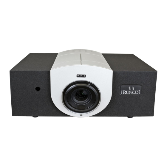
• INTAKE VENT Internal fans draw cool air into the projector through this vent. • RUNCO LOGO The logo can be rotated to match the projector orientation: inverted (ceiling-mounted) or upright. To rotate the logo, grip it at the sides, pull it away from the projector and rotate it 180 degrees. -
Page 22: Q-750I Input Panel
Controls and Functions • FRONT BEZEL RETAINING SCREW Loosen this screw to allow removal of the decorative front bezel, which provides access to the lens shift controls (refer to Lens Shift on page 36). • ZOOM RING Rotate this to change the projected image size. •... - Page 23 Controls and Functions 1. HDMI 1, HDMI 2 (Digital) HDCP-compliant digital video inputs for connecting an HDMI or DVI source. 2. POWER INPUT (100 to 240 VAC) Connect the Q-750i to power here. 3. RGB Provides a standard, 15-pin VGA-style connection to either an RGB or component high-definition source, or to a personal computer.
-
Page 24: Q-750I Remote Control
Controls and Functions Figure 2-3 shows the Q-750i remote control, and the paragraphs that follow describe its functionality. Q-750i Remote Control LIGHT SOURCE S-VID HDMI1 HDMI2 INFO ENTER EXIT MENU CONT TINT PICTURE MEMORY CUST1 CUST2 NIGHT ASPECT RATIO 16:9 LBOX VWIDE CINEMA... - Page 25 Controls and Functions 1. LIGHT Press to illuminate the buttons. 2. ON / OFF Use these buttons to turn the projector on or off. 3. Source Selection Buttons: Press to select Composite video input as the source. S-VID (S-Video) Press to select the S-Video input as the source. HDMI 1 / HDMI 2 Press to select an HDMI input.
- Page 26 Controls and Functions 6. Memory Preset Buttons: CUST1 Press to recall settings for the current input from the “Custom 1” memory preset. ISF NIGHT Press to recall settings for the current input from the “ISF Night” memory preset. ISF DAY Press to recall settings for the current input from the “ISF Day”...
-
Page 27: Installation
3. Installation To install batteries in the remote control: Remote Control 1. Slide the battery compartment cover in the direction of the arrow to remove it. 2. Install two AAA batteries with the correct polarity. 3. Replace the cover. • Make sure that the battery polarities are correct when installing the batteries. Notes on Batteries •... -
Page 28: Quick Setup
Installation Table 3-1 gives a quick overview of the Q-750i installation process. The sections following this one provide detailed instructions. Quick Setup Installation should be performed by a qualified custom video Note installation specialist. Table 3-1. Installation Overview For Details, Refer to Step Procedure page... -
Page 29: Installation Considerations
Installation Proper installation of your projector will ensure the quality of your display. Whether you are installing a projector temporarily or permanently, you should take the following into Installation account to ensure your projector performs optimally. Considerations Choose the installation type that best suits your needs: front or rear screen, floor mount or Installation Type inverted mount. -
Page 30: Throw Distance
Installation Throw Distance Throw distance is the distance measured from the front of the projector to the screen. This is an important calculation in any projector installation as it determines whether or not you have enough room to install your projector with a desired screen size and if your image will be the right size for your screen. - Page 31 Installation Table 3-3. Throw Ratios for the Q-750i Series (Note) (continued) Throw Range in Throw Ratio Throw Range in Throw inches, with with inches, with Ratio with 72.6x40.8-inch Primary 96x40.8-inch (2.35:1) Projector Model Primary (1.78:1) Screen Lens and Screen Lens Only Anamorphic Minimum Maximum Minimum Maximum...
-
Page 32: Vertical And Horizontal Position
Installation Vertical and Horizontal Proper placement of the projector relative to the screen will yield a rectangular, Position perfectly-centered image that completely fills the screen. Ideally, the projector should be positioned perpendicular to the screen and in such a way that the lens center is aligned with either the top or bottom edge of the screen area, and centered horizontally. -
Page 33: Horizontal Lens Shift (Example Only)
Installation Vertical Lens Shift (Standard Q-750i): The Q-750i provides up to 60% of vertical lens shift up or down. For example, with a 100 x 56 inch (1.78:1) screen, you can shift the image up to 33.60 inches (0.85 meters) above or below the screen center. Vertical Lens Shift (Q-750i/CineWide or Q-750i/CineWide with AutoScope): The Q-750i provides up to 25% of upward vertical lens shift and up to 60% of downward vertical lens shift. -
Page 34: Folded Optics
Installation 1. With no vertical or horizontal lens shift, the lens center and Note screen center are aligned with each other. 2. Vertical shift limits are percentages of the screen height. Horizontal shift limits are percentages of the screen width. 3. -
Page 35: Installing The Primary Projection Lens (Q-750I Ultra Only)
Installation The Q-750i primary projection lens is shipped separately from the projector. Proceed as follows to install it: Installing the Primary Projection Lens 1. Carefully remove the projector from the shipping container and place it on a flat (Q-750i Ultra only) surface. -
Page 36: Installing The Lens
Installation Installing the Lens 5. Carefully remove the lens and other installation hardware (in a small plastic bag) from the shipping container. 6. Remove the rear cap from the lens. This protective cap is only used during shipping to protect the lens from damage. 7. - Page 37 Installation 10. Install the two (2), black plastic retaining clips (also provided with the lens) on either side of the lens cavity. Each clip is held in place with two (2), captive Phillips screws. The white, plastic standoffs serve as “handles” to make removing the clips easier. 11.
-
Page 38: Installing The Optional Cinewide/Autoscope Lens Mount
Installation If you are installing a standard (non-CineWide) Q-750i, skip this step and proceed with Mounting the Q-750i (page 29). Installing the Optional CineWide/AutoScope If you are installing a Q-750i/CineWide projector equipped with a Lens Mount cylindrical (Rainier II or McKinley) anamorphic lens, proceed with Installing the Fixed CineWide Base Plate (page 27). -
Page 39: Installing The Autoscope Lens Motor
Installation Figure 3-6 shows the Q-750i/CineWide with AutoScope motor assembly. Installing the AutoScope Lens Motor CineWide with AutoScope Ceiling Mt. Adapter/ Projector Stand, Right Screw, Phillips Pan-Head, M6-1.0 x 12mm (14x) CineWide with AutoScope Ceiling Mt. Adapter/ Projector Stand, Left AutoScope Lens Motor... - Page 40 Installation Remove Projector Front Feet: Remove Place the projector upside down on a blanket or other soft surface. Loosen and remove the two front feet on the projector. Install Ceiling Mount Adapters/Projector Stands: For ceiling installations, these brackets bring the mounting points for the projector mounting plate (included with the projector ceiling mount kit) from the bottom of the projector up and around the AutoScope lens motor housing.
- Page 41 Installation Figure 3-7. Q-750i with Ceiling Mount Adapters/Projector Stands DO NOT OVER-TIGHTEN THE SCREWS. Caution Q-750i Series Installation/Operation Manual...
-
Page 42: Autoscope Lens Motor Installation
Installation Install Lens Motor: 1. Position the AutoScope Lens Motor as shown in Figure 3-8. 2. Line up the mounting holes on the lens motor housing with those on the underside of the projector. 3. Secure the motor to the projector with the eight (8) remaining M6 x 12mm Pan-Head Phillips screws. -
Page 43: Installing The Fixed Cinewide Base Plate
Installation Figure 3-9 shows the cylindrical (Rainier II/McKinley) lens base plate assembly for a Installing the Fixed Q750i/CineWide. CineWide Base Plate Ceiling Mount Rails (part of Ceiling Mount Kit) Screw, Phillips Pan-Head, M6 x 1.0 x 12mm (6x) Anamorphic Lens Base Plate Figure 3-9. - Page 44 Installation To install the fixed CineWide base plate on a Q-750i/CineWide: 1. Place the projector upside down on a blanket or other soft surface. 2. Place the CineWide base plate on the bottom of the projector. 3. If you are mounting the projector on a ceiling: Line up the three holes on the left and right mounting rails (included with the projector ceiling mount kit) with those on the projector and base plate.
-
Page 45: Mounting The Q-750I
Q-750i and suspend it from the (Inverted) ceiling using a specially-designed ceiling mount fixture. Use only the Runco-approved ceiling mount kit designed for your Note projector. Install the mount kit according to the instructions provided with it. -
Page 46: Connecting Source Components To The Q-750I
Installation Connecting Source Connect your video sources to the Q-750i as shown and described in the sections that Components to the Q-750i follow. HDMI/DVI Connections: See Figure 3-10. Use the HDMI input whenever possible. This ensures the highest video quality because the signal is carried in the digital domain throughout the entire signal path, from source component output into the projector. -
Page 47: Rgb Connections
Installation RGB Connections: Connect your personal computer or other RGB source to the RGB input. Optionally, if the source outputs RGB with composite sync, connect the green, blue and red outputs to the Y, Pb and Pr terminals on the COMPONENT 1/SCART input and the sync output to the VIDEO input. -
Page 48: Component Video Connections
Installation Component Video Connections: Connect your component video sources to the COMPONENT 1/SCART, COMPONENT 2 or RGB inputs as shown in Figure 3-12. RCA-to- adapter COMPONEN T VIDEO OUT DTV-Set-Top Box (DTV-STB) BD/DVD Figure 3-12. Component Video Connections Q-750i Series Installation/Operation Manual... - Page 49 Installation Composite/S-Video Connections: Connect your composite and S-Video sources to the Q-750i as shown in Figure 3-13. S-Video Camcorder Composite Gaming Console Figure 3-13. Composite and S-Video Connections Q-750i Series Installation/Operation Manual...
-
Page 50: Controller Connection
Installation RS-232 Controller Connect a PC or home theater control/automation system (if present) to the RS-232 port Connection on the Q-750i; see Figure 3-14. Use a standard, 9-pin serial cable, wired straight-through. For more information about using this connection, refer to Serial Communications on page 75. -
Page 51: Connecting An External Ir Receiver
Installation If infrared signals from the remote control cannot reach the projector due to excessive Connecting an External IR distance or obstructions such as walls or cabinet doors, you can connect an external IR Receiver repeater system to the IR INPUT on the Q-750i to extend the range of the remote control. See Figure 3-16. -
Page 52: Turning On The Power
Installation 1. Turn on your source components. Turning on the Power 2. If this is an AutoScope-equipped projector, turn on the main power switch at the rear of the AutoScope lens motor. The lens motor power switch is located next to the AC input (see above). -
Page 53: Changing The Osd Language
Installation When you turn on the Q-750i for the first time, the OSD Language Menu appears. 3.10 Changing the OSD The Q-750i can display the menus in English, French, German, Italian, Spanish, Swedish, Language Portuguese or Russian. Press to select a language. Then, press ENTER to confirm your selection. 3.11 If the Q-750i is installed behind the screen, you must change the picture orientation to match the installation method. -
Page 54: Installing And Adjusting The Cinewide Anamorphic Lens
Installation 3.12 If you are installing a CineWide-equipped projector, proceed as follows to install and adjust the anamorphic lens. Installing and Adjusting the CineWide Anamorphic It is extremely important that the primary lens is properly Note Lens adjusted before you install the anamorphic lens. Ensure that the image from the primary lens is perfectly centered on the screen. - Page 55 Installation Attaching Lens Mounting Assembly to Lens Motor Carriage Plate or Fixed CineWide Base Plate: 1. Remove the two Yaw/X Adjustment Levers (item #8) from the bottom of the Anamorphic Lens Holder (item #5). 2. Place the Anamorphic Lens Holder on top of the AutoScope Carriage Plate or Fixed CineWide Base Plate (item #7).
- Page 56 Installation Select the Appropriate CineWide Scaling Method: CineWide and CineWide with AutoScope both produce the same image geometry for a given aspect ratio (refer to Table 4-2). However, when the viewer selects the 16:9, 4:3, Letterbox or VirtualWide aspect ratio, CineWide uses different scaling algorithms to compensate for the fact that the anamorphic lens is always in front of the primary lens.
- Page 57 Installation 3. Slowly move the anamorphic lens into place (from right to left or vice versa) so that there are no shadows on either side of the screen: Too Far Left Correct position Too Far Right 4. When the horizontal position is properly set, tighten the Yaw/X-Adjustment Levers to secure the lens in place.
- Page 58 Note properly adjusted, especially at shorter throw distances. If this is the case, Runco recommends that you slightly over-scan the image into the screen frame area to mask the distortion. Adjusting the Yaw: Loosen the Yaw/X-Adjustment Levers to allow the lens to pivot freely from side to side.
- Page 59 Installation Correct Position Wrong Position Once the proper lens angle has been set, firmly tighten the Yaw/X-Adjustment Levers to secure the lens in place. Geometry: 1. Input an anamorphic cross-hatch test pattern to the projector. 2. Unscrew the Anamorphic Lens just enough to allow it to rotate freely. 3.
- Page 60 Installation Notes: Q-750i Series Installation/Operation Manual...
-
Page 61: Operation
4. Operation When you turn on the Q-750i, it switches to the last selected input and looks for a valid signal. Selecting An Input Source Use these buttons on the remote control to select an SOURCE input source directly. S-VID HDMI1 HDMI2 You can assign the HD 1, HD 2 and HD 3 buttons to any... - Page 62 Operation For each source, Table 4-1 shows which of the other sources are available as a PIP source. Table 4-1. Available Main and PIP Source Combinations PIP Input Source VIDEO S-VIDEO SCART COMP 1 COMP 2 RGB HDMI 2 HDMI 1 √...
-
Page 63: Using The On-Screen Menus
Saturation (Red / Yellow / Green / Cyan / Blue / Magenta) Level (Red / Yellow / Green / Cyan / Blue / Magenta) Runco Smart Color (RSC) (On or Off) White Balance (Red / Green / Blue Gain) Figure 4-1. Q-750i OSD Menu Structure... -
Page 64: Main
Main The Q-750i Main Menu, shown in Figure 4-2, provides access to the most commonly-used projector functions. 1. For best results, Runco recommends that you set Note ConstantContrast to Off before adjusting Brightness, Contrast and other image quality settings in this menu (refer to ConstantContrast on page 60). - Page 65 Operation Aspect Ratio: To change the aspect ratio (size and shape) of the projected image, press to highlight Aspect Ratio. Use the buttons to select the appropriate aspect ratio for your screen size, installed lens configuration and the type of program material being viewed, then press ENTER;...
- Page 66 Operation Table 4-2. Aspect Ratio Settings (continued) Aspect Geometry of Projected Image Aspect Ratio of Ratio Description With Standard Lens Source With Anamorphic Lens (2.35:1 Screen) Setting (1.78:1 Screen) Signal 16:9 4:3 linearly scales the source active image horizontally and vertically to fill a 4:3 rectangle which is centered and the same height as the...
- Page 67 Operation Table 4-2. Aspect Ratio Settings (continued) Aspect Geometry of Projected Image Aspect Ratio of Ratio Description With Standard Lens Source With Anamorphic Lens (2.35:1 Screen) Setting (1.78:1 Screen) Signal Select Cinema to view 2.35 source material in its native aspect ratio. With a 16:9 screen and a non-CineWide projector (no anamorphic lens), the...
- Page 68 Operation Memory: Select Memory from the Main menu, then press ENTER to recall image quality settings previously saved, or to save changed settings in any of four memory locations. • Recall Memory: Select Recall Memory from the Memory menu to recall saved image quality settings.
- Page 69 Operation Brightness: On your external test pattern source, select a PLUGE pattern. (PLUGE is an acronym for “Picture Line-Up Generation Equipment.”) Figure 4-3 shows a typical PLUGE pattern. Below Black Above Black Figure 4-3. Typical PLUGE Pattern for Adjusting Brightness PLUGE patterns vary but generally consist of some combination of black, white and gray areas against a black background.
- Page 70 Operation Brightness and Contrast controls are interactive. A change to one Note may require a subtle change to the other in order to achieve the optimum setting. Color: To adjust the overall color intensity, select Color from the Main menu. Decrease this setting if colors are overly saturated;...
- Page 71 Operation Overscan: Some television programs are produced based on the assumption that older television sets may not display the outer edges of the broadcast picture area. Overscan effectively hides these inactive, outer edges of the image. Choose one of the following: •...
- Page 72 Operation Input Select: To select a video source, press to highlight Input Select, then press ENTER. This displays the Input Select sub-menu, shown in Figure 4-7. The default source selection is HDMI 1. All sources that are not available per the source enable function (refer to Input Enable on page 65) are grayed out.
-
Page 73: Advanced
Operation Use the controls in the Advanced menu, shown in Figure 4-8, to perform advanced image Advanced adjustments. Figure 4-8. Q-750i Advanced Menu Color Space: Select Color Space from the Advanced menu to choose the color space of the source signal for HDMI, RGB, and component connections. •... - Page 74 Operation Video Standard: Select Video Standard from the Advanced menu to specify the color system for composite video or S-Video input signals. Different countries use different formats for video signals. Select the appropriate Video Standard for your region: • Auto: The color systems are automatically identified and the format is set accordingly. •...
- Page 75 • Select SMPTE-C to use the color gamut defined in SMPTE 170M-1999. • Select EBU to use the color gamut defined in EBU Tech. 3213-E. • Select Native for Runco's recommended Personal Color Equalizer preset for typical video sources. It displays the fully saturated LED color gamut with appropriate color brightness, hue, and Runco Smart Color settings.
- Page 76 (Off) the ConstantContrast algorithm in the optical engine. ConstantContrast uses a dynamic LED driver that modulates light to the DMD based on the actual content of the video material. Runco recommends that you disable ConstantContrast before adjusting Brightness, Contrast or other image settings.
- Page 77 Operation Fine Sync: To fine-tune the position and other image attributes, choose Fine Sync from the Advanced menu and press ENTER. This displays the Fine Sync sub-menu, shown in Figure 4-10. Figure 4-10. Fine Sync Sub-Menu • V Position: This control adjusts the vertical position of the image within the designated image area, up to 25 per cent of the image height up or down.
-
Page 78: Pce Sub-Menu
Operation Steady flickering or several soft vertical stripes or bands across the entire image indicates poor pixel tracking. Proper pixel tracking helps ensure that the image quality is consistent across the screen, that aspect ratio is maintained and that pixel phase (see above) can be optimized. -
Page 79: Cie 1931 Color Coordinate Diagram And Effect Of Pce Hue And Saturation Controls
Figure 4-12. CIE 1931 Color Coordinate Diagram and Effect of PCE Hue and Saturation Controls RSC™ (Runco Smart Color): Set RSC to On to to improve the accuracy of flesh tones and increase color saturation, without sacrificing the purity of other colors. -
Page 80: System
Operation System Use the controls in the System menu, shown in Figure 4-13, to change the display orientation and perform other, common installation tasks. Figure 4-13. Q-750i System Menu Q-750i Series Installation/Operation Manual... - Page 81 Operation Input Enable: To enable or disable selection of a source, choose Input Enable from the System menu and press ENTER. This displays the Input Enable sub-menu, shown in Figure 4-14. Figure 4-14. Input Enable Sub-Menu • HDMI 1/HDMI 2: Enables or disables the HDMI 1 and HDMI 2 sources. •...
- Page 82 Operation PIP Position: To change the position of the PIP image, choose PIP Position from the System menu; see Figure 4-15. Choose one of the following: • Top Left: This places the PIP source into a 644x362 designated image area at the top left of the screen.
- Page 83 The default setting, Auto, automatically determines the orientation using an internal sensor. Logo Display: This controls whether or not the Runco logo appears during startup. Power On Chime: This controls the audible chime at startup. Q-750i Series Installation/Operation Manual...
-
Page 84: Control
Operation Control Select Control from the Main Menu to set various options related to control of the projector. HD 1 Key / HD 2 Key / HD 3 Key: These menu items assign the function of the HD 1, HD 2 and HD 3 buttons on the remote. There are eight sources corresponding to the eight connections to the projector. -
Page 85: Language
Operation Trigger 1: Select Trigger 1 from the Control menu to specify when the Trigger 1 port outputs 12 volts. There is a three-second delay before activation to prevent operation while selecting an aspect ratio. • AutoScope causes the port to output 12 volts whenever the the Cinema or Virtual Cinema aspect ratio is active. -
Page 86: Service
• Pixel Clock • Signal Format • H/V Refresh Rate Should you ever need to contact Runco Technical Support, this information will help them answer your questions and/or resolve product performance issues. Figure 4-17. Q-750i Service Menu You can also perform various maintenance tasks from this menu. - Page 87 Operation Test Patterns: The Q-750i has numerous internal test patterns that are useful to technicians for advanced calibration, measurement and fault isolation purposes. To access them, select Test Patterns from the Service menu and set it to On. The available test patterns are: •...
- Page 88 Operation Notes: Q-750i Series Installation/Operation Manual...
-
Page 89: Maintenance And Troubleshooting
Table 5-1 provides some general guidelines for troubleshooting problems you may encounter with the Q-750i. If the suggested solutions fail to resolve the problem or if you Troubleshooting Tips encounter an issue not described here, please contact Runco Technical Support. Table 5-1. Troubleshooting Chart Symptom... - Page 90 Ensure that the intake and exhaust vents are not blocked. Turn the projector back on. If the problem persists, please contact Runco Technical Support for assistance. LED lights solid red. • Fans are not working • Power off the Q-750i and properly or power-on allow it to cool down.
-
Page 91: Serial Communications
6. Serial Communications To interface the Q-750i with a home theater automation/control system or a PC running terminal emulation software: RS-232 Connection and Port Configuration 1. Connect it to your control system or PC as shown in Figure 3-14. 2. Start a terminal session on your PC using a terminal-emulation program, such as HyperTerminal. - Page 92 Serial Communications Table 6-1 lists the serial command key names and IR codes. Table 6-1. Serial Command Key Names and IR Codes RS232 IR Code Remote Button Description Keyname Turn power on. 0x00 pow.on Turn power off. 0x45 pow.off Switch the active source to Video. 0x02 src.video Switch the active source to S-Video.
- Page 93 Serial Communications Table 6-1. Serial Command Key Names and IR Codes (continued) RS232 IR Code Remote Button Description Keyname Bring up or cancel color slider. 0x04 color Bring up or cancel tint slider. 0x03 tint TINT Changes to ISF Night preset. 0x5f isf.nigh IS F...
-
Page 94: Operations Commands
Serial Communications Table 6-1. Serial Command Key Names and IR Codes (continued) RS232 IR Code Remote Button Description Keyname The projector does not respond to this key. 0x10 (none) ZOOM The projector does not respond to this key. 0x13 (none) LENS Activates remote backlighting when pressed. - Page 95 Serial Communications Input: op sharp.mode = 1 [CR] Response: OP SHARP.MODE = 1 [CR] Input: op sharp.simple = 50 [CR] Response: OP SHARP.SIMPLE = NA [CR] Input: op sharp.simple ? [CR] Response: OP SHARP.SIMPLE = NA [CR] The last three commands show what happens when a control is grayed out. In this case, the sharpness mode was set to advanced (value = 1) and then the simple sharpness slider was attempted to be adjusted and queried.
- Page 96 Serial Communications Table 6-2. Serial Commands (continued) Operation Commands Values Notes 0 = Off pip.select 1 = HDMI 1 2 = HDMI 2 3 = RGB 4 = Component 1 5 = Component 2 6 = S-Video 7 = Video 8 = SCART resync (exe-...
- Page 97 Serial Communications Table 6-2. Serial Commands (continued) Operation Commands Values Notes 0-200 Red/Green/Blue Offset red.off = ? + - green.off blue.off 0-200 Red/Green/Blue Gain red.gain = ? + - green.gain blue.gain 0-200 vert.pos = ? + - 0-200 horiz.pos = ? + - 0-200 phase = ? + -...
- Page 98 Serial Communications Table 6-2. Serial Commands (continued) Operation Commands Values Notes 0 = HDMI 1 HD 1/HD 2/HD 3 key 1.key 1 = HDMI 2 source assignments. 2.key 2 = RGB 3.key 3 = YPrPb 1 4 = YPrPb 2 5 = S-video 6 = Video 7 = SCART...
- Page 99 Serial Communications Table 6-2. Serial Commands (continued) Operation Commands Values Notes 0 = Off blue.only 1 = On 0 = White pattern 1 = Black 2 = Red 3 = Green 4 = Blue 5 = Cyan 6 = Magenta 7 = Yellow 8 = ANSI Checker- board...
- Page 100 0-200 PCE “White Balance” white.red.gain = ? + - settings. white.green.gain white.blue.gain 0 = Off Runco Smart Color (RSC) hue.correct 1 = On 0 = Standby status 1 = Powering Up 2 = Displaying 3 = Cooling Down 4 = Error...
-
Page 101: Rs-232 Error Codes
Serial Communications If an errcode ? command returns one of the following values, you have encountered a RS-232 Error Codes likely system error requiring the attention of a qualified service technician. Try resetting the projector by powering it off, allowing it to cool and powering it on again. Refer to Table 6-3 and contact your dealer if the problem persists. - Page 102 Serial Communications Notes: Q-750i Series Installation/Operation Manual...
-
Page 103: Specifications
Digital Light Processing™ (DLP™),Single-Chip, 16:9 SuperOnyx™ DMD™ with InfiniLight Illumination Illumination: RGB InfiniLight LEDs for 135% NTSC color gamut with Runco Smart Color and Personal Color Equalizer Native Resolution: Full HD, 1920 x 1080 (16:9) Aspect Ratios: 4:3, Letterbox, 16:9, VirtualWide, Cinema, Virtual Cinema... - Page 104 Colors have up to 50% higher contrast than Mercury or Xenon lamp systems. These are typical projector brightness and contrast specifications found in most companies’ sales literature. Runco includes these measurements in its literature to allow for direct comparison with other manufacturers’ projectors. These measurements are typically taken at 9,000K to 13,000K to get expected performance data when the projector is used in professional, commercial and industrial displays.
-
Page 105: Overall Dimensions - Q-750I
Specifications Figure 7-1 shows the Q-750i dimensions (all dimensions are in millimeters and [inches]). Overall Dimensions – Q-750i Figure 7-1. Overall Dimensions – Q-750i Q-750i Series Installation/Operation Manual... -
Page 106: Overall Dimensions - Q-750I/Cinewide With Autoscope
Specifications Figure 7-2 shows the Q-750i/CineWide with AutoScope dimensions (all dimensions are in millimeters and [inches]). Overall Dimensions – Q-750i/CineWide with AutoScope Figure 7-2. Overall Dimensions – Q-750i/CineWide with AutoScope Q-750i Series Installation/Operation Manual... -
Page 107: Overall Dimensions - Q-750I Ultra
Specifications Figure 7-3 shows the Q-750i Ultra dimensions (all dimensions are in inches and [millimeters]). Overall Dimensions – Q-750i Ultra Figure 7-3. Overall Dimensions – Q-750i Ultra Q-750i Series Installation/Operation Manual... -
Page 108: Overall Dimensions - Q-750I Ultra/Cinewide With Autoscope
Specifications Figure 7-4 shows the Q-750i Ultra/CineWide with AutoScope dimensions (all dimensions are in inches and [millimeters]). Overall Dimensions – Q-750i Ultra/CineWide with AutoScope Figure 7-4. Overall Dimensions – Q-750i Ultra/CineWide with AutoScope Q-750i Series Installation/Operation Manual... -
Page 109: Supported Timings
Specifications Table 7-2 lists the signal types supported by each input on the Q-750i. Supported Timings Table 7-2. Supported Signal Timings by Input Supported? (√ = Yes, – = No) Horizontal Refresh Pixel Frequency Format Resolution Frequency Component 1 HDMI 1 Composite Rate (Hz) (MHz) - Page 110 Specifications Table 7-2. Supported Signal Timings by Input (continued) Supported? (√ = Yes, – = No) Horizontal Refresh Pixel Frequency Format Resolution Frequency Component 1 HDMI 1 Composite Rate (Hz) (MHz) (kHz) Component 2 HDMI 2 S-Video √ √ √ 1080/50p 1920x1080 50.00...
- Page 112 020-1018-01 Rev. A October 2011 Runco International • (800) 23RUNCO • Fax (503) 748-8161 • www.runco.com...
Need help?
Do you have a question about the Quantum Color Q-750i Series and is the answer not in the manual?
Questions and answers