Table of Contents
Advertisement
Available languages
Available languages
Quick Links
MODEL
MODELE
MODELO
INSTRUCTION MANUAL AND SAFETY INSTRUCTIONS
Improper and unsafe use of this power tool can result in death or serious bodily injury!
This manual contains important information about product safety. Please read and
understand this manual before operating the power tool. Please keep this manual
available for others before they use the power tool.
MODE D'EMPLOI ET INSTRUCTIONS DE SECURITE
Une utilisation incorrecte et dangereuse de cet outil motorisé peut entraîner la mort
ou de sérieuses blessures corporelles!
Ce mode d'emploi contient d'importantes informations à propos de la sécurité de
ce produit. Prière de lire et d'assimiler ce mode d'emploi avant d'utiliser l'outil
motorisé. Garder ce mode d'emploi à la disponibilité des autres utilisateurs avant
qu'ils utilisent l'outil motorisé.
MANUAL DE INSTRUCCIONES E INSTRUCCIONES DE SEGURIDAD
¡La utilización inapropiada e insegura de esta herramienta eléctrica puede resultar
en lesiones serias o en la muerte!
Este manual contiene información importante sobre la seguridad del producto. Lea y
comprenda este manual antes de utilizar la herramienta eléctrica. Guarde este manual
para que puedan leerlo otras personas antes de que utilicen la herramienta eléctrica.
DOUBLE INSULATION
DOUBLE ISOLATION
AISLAMIENTO DOBLE
C 10FCD
WARNING
AVERTISSEMENT
ADVERTENCIA
COMPOUND SAW
SCIE A ONGLET INCLINABLE
SIERRA COMPUESTA
Advertisement
Table of Contents

Subscribe to Our Youtube Channel
Related Manuals for Hitachi C 10FCD


Summary of Contents for Hitachi C 10FCD
- Page 1 MODEL COMPOUND SAW C 10FCD MODELE SCIE A ONGLET INCLINABLE MODELO SIERRA COMPUESTA INSTRUCTION MANUAL AND SAFETY INSTRUCTIONS WARNING Improper and unsafe use of this power tool can result in death or serious bodily injury! This manual contains important information about product safety. Please read and understand this manual before operating the power tool.
-
Page 2: Table Of Contents
CONTENTS English Page Page IMPORTANT INFORMATION ........3 APPLICATIONS ............10 MEANINGS OF SIGNAL WORDS ....... 3 PREPARATION BEFORE OPERATION ..... 10 BEFORE USING ............12 SAFETY BEFORE CUTTING ............13 IMPORTANT SAFETY INSTRUCTIONS PRACTICAL APPLICATIONS ........14 FOR USING ALL POWER TOOLS ......3 SAW BLADE MOUNTING REPLACEMENT PARTS .......... -
Page 3: Important Information
Hazards that must be avoided to prevent bodily injury or machine damage are identified by WARNINGS on the tool and in this Manual. Never use this tool in a manner that has not been specifically recommended by HITACHI, unless you first confirm that the planned use will be safe for you and others. - Page 4 English 10. ALWAYS SECURE THE WORKPIECE TO THE FENCE OR THE TABLE. Use clamps or a vise to hold the workpiece in place. It is safer than using your hand and it frees both hands to operate the tool. 11. NEVER OVERREACH. Always keep proper footing and balance when working with the tool.
- Page 5 English When replacing the saw blade, always confirm that the rpm rating of the new blade is correct for use on this tool. Always shut off the power and wait for the saw blade to completely stop rotating before doing any maintenance or adjustments.
-
Page 6: Replacement Parts
REPLACEMENT PARTS When servicing use only identical replacement parts. Repairs should be conducted only by a Hitachi authorized service center. USE PROPER EXTENSION CORD Make sure your extension cord is in good condition. When using an extension cord, be sure to use one heavy enough to carry the current your product will draw. -
Page 7: Double Insulation For Safer Operation
English DOUBLE INSULATION FOR SAFER OPERATION To ensure safer operation of this power tool, HITACHI has adopted a double insulation design. “Double insulation” means that two physically separated insulation systems have been used to insulate the electrically conductive materials connected to the power supply from the outer frame handled by the operator. Therefore, either the symbol “... -
Page 8: Operation And Maintenance
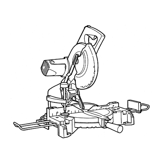
English OPERATION AND MAINTENANCE NOTE: The information contained in this Instruction Manual is designed to assist you in the safe operation and maintenance of the power tool. Some illustrations in this Instruction Manual may show details or attachments that differ from those on your own power tool. NAME OF PARTS Switch Lock Head... -
Page 9: Specifications
English SPECIFICATIONS Item Model C 10FCD Motor Type Series commutator motor Power source Single-phase AC 60Hz Voltage (Volts) Full-load current (Amp) Applicable Outside Dia. 10" (255 mm) saw blade Hole Dia. 5/8" (15.9 mm) No load speed 3800rpm Max. Height 2-23/32"... -
Page 10: Applications
English APPLICATIONS Wood, plywood, color board, soft fabric board, hard board similar materials and aluminum sash. PREPARATION BEFORE OPERATION Make the following preparations before operating the power tool: 1. Installation 5/16" (8 mm) Bolt 19-1/16" (484 mm) 3/8" (10 mm), 4 Holes Base 16-27/32"... - Page 11 English 2. Releasing the plunger handle During operation fit the plunger handle stoppers Plunger Handle into the shallow slot. Plunger Handle Clockwise During transport, fit the plunger handle into the deep slot. Pull out to disengage. NOTE: This position is not be Rotate the knob 1/4 turn used for any cutting and fit the pin stoppers...
-
Page 12: Before Using
English BEFORE USING 1. Make sure the power source is appropriate for the tool. WARNING: Never connect the power tool unless the available AC power source is of the same voltage as that specified on the nameplate of the tool. Never connect this power tool to a DC power source. -
Page 13: Before Cutting
English BEFORE CUTTING 1. Cutting a groove on the table insert. A groove has to be cut in the table insert, before starting Table Insert operation. Secure a piece of wood about 5-1/8" (130 mm) wide to the table with the vise assembly, to prevent the breakage of the table insert. -
Page 14: Practical Applications
English 4. Securing the workpiece WARNING: Always clamp or vise to secure the workpiece to the fence; otherwise the workpiece might be thrust from the table and cause bodily harm. 5. Installing the extension wings (Optional accessory) The extension wings help keep longer workpieces stable and in place during the cutting operation. - Page 15 English 1. Switch operation Switch The switch lock is designed to prevent inadvertent operation of the Lock power tool. To operate the power tool, it is necessary to first push up the switch Hole lock as shown in Fig. 17. The trigger switch will not operate unless the switch lock has been pushed up.
- Page 16 English 3. Using the vise assembly (Optional accessory) (1) The vise assembly can be mounted on either the left side base or the right side base, and can be moved back and forth according to the width of the workpiece. Insert support of vise assembly into the hole located on either the left side base or the right side of the base as shown in Fig.
- Page 17 English 6. Bevel cutting procedures (1) Loosen the clamp lever and bevel the saw blade to the Bevel Angle left or to the right. Scale When tilting the motor head to the right, pull up the locating bar as indicated in Fig. 23. Indicator Clamp Lever...
- Page 18 English Type of To process crown molding at To process crown molding at positions 1 and 4 in Fig. 25. positions 2 and 3 in Fig. 25. Crown Molding Miter Angle Bevel Angle Miter Angle Bevel Angle Setting Setting Setting Setting 45°...
- Page 19 English (4) Setting to cut crown moldings at positions w and e in Fig. 25 (see Fig. 32): q Turn the table to the left and set the Miter Angle as follows: * For 45° type crown moldings: 35.3° * For 38° type crown moldings: 31.6° w Tilt the head to the right and set the Bevel Angle as follows: * For 45°...
-
Page 20: Saw Blade Mounting And Dismounting
English SAW BLADE MOUNTING AND DISMOUNTING WARNING: To prevent an accident or personal injury, always turn off the trigger switch and disconnect the power plug from the receptacle before removing or installing a saw blade. 1. Mounting the saw blade (1) Rotate blade guard (plastic), to top position. -
Page 21: Overload Protective Device For Poly-V-Belt
English 2. Dismounting the saw blade Dismount the saw blade by reversing the mounting procedures described in paragraph 1 above. The saw blade can easily be removed after lifting the cutter shaft guard. CAUTION: Never attempt to install saw blades larger than 10" (255 mm) in diameter. Always install saw blades that are 10"... -
Page 22: Service And Repairs
To assure that only authorized replacement parts will be used and that the double insulation system will be protected, all service (other than routine maintenance) must be performed by an AUTHORIZED HITACHI POWER TOOL REPAIR CENTER ONLY. NOTE: Specifications are subject to change without any obligation on the part of HITACHI. -
Page 23: Français
AVERTISSEMENTS sur l’outil électrique et dans ce mode d’emploi. Ne jamais utiliser cet outil électrique d’une manière qui n’est pas spécifiquement recommandée par HITACHI sans avoir d’abord vérifié que l’utilisation prévue est sans danger pour vous et les autres. - Page 24 Français 9. TOUJOURS PORTER DES LUNETTES DE PROTECTION PENDANT LE TRAVAIL POUR ÉVITER TOUT RISQUE DE BLESSURE DES YEUX. Les lunettes ordinaires n’assurent pas une protection suffisante parce que leurs verres sont uniquement résistants aux chocs, ce NE sont PAS des verres de sécurité.
- Page 25 Français Consignes de sécurité spéciales pour cet outil électrique AVERTISSEMENT: Pour éviter tout risque de blessure, les consignes de sécurité spéciales suivantes devront être respectées lors de l’utilisation de l’outil. CHOSES A FAIRE TOUJOURS OBSERVER LES CONSIGNES SUIVANTES POUR GARANTIR UNE UTILISATION EN TOUTE SÉCURITÉ: Bien lire le manuel et se familiariser avec les consignes de sécurité...
- Page 26 Français CHOSES A NE PAS FAIRE POUR GARANTIR UNE UTILISATION EN TOUTE SÉCURITÉ, NE JAMAIS VIOLER LES CONSIGNES SUIVANTES: Ne jamais utiliser l’OUTIL ELECTRIQUE si l’on ne comprend pas bien les instructions de ce manuel. Ne jamais s’éloigner de l’OUTIL ELECTRIQUE sans débrancher auparavant son cordon d’alimentation. Ne jamais utiliser l’OUTIL ELECTRIQUE quand on est fatigué, après avoir pris des médicaments ou consommé...
-
Page 27: Pieces De Rechange
électrique. DOUBLE ISOLATION POUR UN FONCTIONNEMENT PLUS SUR Pour assurer un fonctionnement plus sûr de cet outil électrique, HITACHI a adopté une conception à double isolation. “Double isolation” signifie que deux systèmes d’isolation physiquement séparés ont été utilisés pour isoler les matériaux conducteurs d’ électrique connectés à l’outil électrique à partir du cadre extérieur manipulé... -
Page 28: Utilisation Et Entretien
Français UTILISATION ET ENTRETIEN REMARQUE: Les informations contenues dans ce manuel sont destinées à vous aider à utiliser et à entretenir l’OUTIL ELECTRIQUE en toute sécurité. Certaines illustrations de ce manuel peuvent montrer des détails ou des fixations qui diffèrent de ceux de votre OUTIL ELECTRIQUE. -
Page 29: Spécifications
Français SPÉCIFICATIONS Article Modèle C 10FCD Moteur Type Moteur à commutateur série Alimentation Courant alternatif monophasé 60 Hz Tension (volts) Courant à pleine charge (Amp) 13 Lame applicable Diámetro exterior: 255 mm (10") Dia. d’orifice 15,9 mm (5/8") Vitesse à vide 3800 tr/mn Biseau 0°... -
Page 30: Applications
Français APPLICATIONS Bois, contreplaqué, planches à tissu souple, planches dures et autres matériaux semblables et cadres d’aluminium. PRÉPARATION AVANT L’UTILISATION Avant de mettre l’outil électrique en service, effectuer les préparations suivantes : 1. Installation Boulon de 8 mm (5/16") 484 mm (19-1/16") 10 mm (3/8"), 4 Holes Socle 428 mm (16-27/32") - Page 31 Français 2. Libérer la goupille de verrouillage. Pendant le fonctionnement, insérer les butées de la poignée à plongeur dans la Poignée à plongeur fente mince. Poignée à plongeur Sens des aiguilles d’une montre Pendant le transport, insérer les butées de la poignée à plongeur dans la fente creuse.
-
Page 32: Avant L'utilisation
Français AVANT L’UTILISATION 1. S’assurer que la source d’alimentation convient pour l’outil. AVERTISSEMENT: Ne jamais raccorder l’outil électrique si l’alimentation secteur n’est pas de la tension spécifiée sur la plaque signalétique de l’outil Ne jamais raccorder l’outil à une source de courant continu. 2. -
Page 33: Avant La Coupe
Français AVANT LA COUPE 1. Coupe d’une encoche dans la plaque d’insertion Avant de mettre l’outil en service, il faudra découper une Plaque encoche dans la plaque d’insertion. Fixer un morceau de d’insertion bois d’environ 130 mm de large sur la table avec l’ensemble d’étau pour éviter que la plaque d’insertion ne se rompe. -
Page 34: Applications Pratiques
Français 4. Fixation de la pièce AVERTISSEMENT: Toujours utiliser un dispositif de fixation ou l’étau pour fixer la pièce à la garde ; sinon, la pièce risque d’être éjectée de la table et de blesser quelqu’un. 5. Installation des servantes (accessoires en option) Les servantes aident à... - Page 35 Français 1. Fonctionnement de l’interrupteur Verrou Le verrou d’interrupteur est conçu pour empêcher tout d’interrupteur fonctionnement accidentel de l’outil électrique. Pour faire marcher l’outil, il faut tout d’abord pousser le verrou Orifice d’interrupteur vers le haut, comme indiqué à la Fig. 17. L’interrupteur à...
- Page 36 Français 3. Utilisation de l’ensemble d’étau (accessoire en option) (1) L’ensemble d’étau pourra être monté sur le socle gauche ou sur le socle droit, et il pourra être déplacé vers l’avant ou vers l’arrière en fonction de la largeur de la pièce. Insérer le support de l’ensemble d’étau dans l’orifice situé...
- Page 37 Français 6. Procédure de coupe de biseau Echelle d’angle de biseau (1) Desserrer le levier de serrage et incliner la lame de scie vers la gauche ou vers la droite. Levier de Pour incliner la tête du moteur vers la droite, tirer sur Indicateur serrage la barre de positionnement comme indiqué...
- Page 38 Français Type de Pour découper une corniche complexe Pour découper une corniche complexe aux positions 1 et 4 de la Fig. 25. aux positions 2 et 3 de la Fig. 25. corniche complexe Réglage Réglage Réglage Réglage d’angle d’angle de d’angle de d’angle d’onglet...
- Page 39 Français (4) Réglage pour des coupes de corniches complexes aux positions w et e de la Fig. 25 (voir Fig. 32) : q Tourner la table vers la gauche et régler l’angle d’onglet comme suit : * Pour des corniches complexes de 45° : 35,3° * Pour des corniches complexes de 38°...
-
Page 40: Installation Et Retrait De La Lame
Français INSTALLATION ET RETRAIT DE LA LAME AVERTISSEMENT: Pour éviter tout risque d’accident ou de blessure, toujours couper l’interrupteur à gâchette et débrancher la fiche de la prise secteur avant de retirer ou d’installer la lame. 1. Installation de la lame (1) Tourner la protection de lame (en plastique) sur la position supérieure. -
Page 41: Dispositif De Protection Anti-Surcharge De La Poly-Courroie En V
Français 2. Retrait de la lame Démonter la lame en procédant dans l’ordre inverse de l’installation décrite au paragraphe 1 ci-dessus. La lame s’enlève facilement si le carter de sécurité est relevé. ATTENTION: Ne jamais tenter d’installer des lames de scie de plus de 255 mm (10") de diamètre. Toujours installer des lames de scie d’un diamètre égal ou inférieur à... -
Page 42: Service Après-Vente Et Réparations
Pour garantir que seules des pièces de rechange agréées seront utilisées et que le système de double isolation sera protégé, il faudra confier toutes les opérations d’entretien (autres que l’entretien de routine) exclusivement à un SERVICE APRES-VENTE D’OUTILS ELECTRIQUES HITACHI AGREE. REMARQUE:... -
Page 43: Español
Manual de instrucciones. No utilice nunca esta herramienta eléctrica de ninguna forma no específicamente recomendada por HITACHI a menos que usted se haya asegurado de que la utilización planeada será segura para usted y otras personas. - Page 44 Español 7. UTILICE SIEMPRE LAS HERRAMIENTAS CORRECTAS. No fuerce nunca una herramienta ni un accesorio para realizar un trabajo para el que no se haya diseñado. 8. ANTES DE TRABAJAR CON LA HERRAMIENTA, VÍSTASE LA ROPA ADECUADA. utilice nunca ropa floja, guantes, corbatas, collares, anillos, brazaletes, ni demás joyas que puedan quedar atrapados en las partes móviles.
- Page 45 Español Normas de seguridad específicas para la utilización de esta herramienta ADVERTENCIA: Las instrucciones de operación específicas siguientes deberán observarse cuando se utilice esta HERRAMIENTA ELÉCTRICA a fin de evitar lesiones. LO QUE DEBERÁ HACERSE TENGA SIEMPRE EN CUENTA LAS NORMAS SIGUIENTES PARA PODER UTILIZAR CON SEGURIDAD ESTA HERRAMIENTA: Antes de intentar utilizar esta HERRAMIENTA ELÉCTRICA, lea este manual y familiarícese con las normas de seguridad y las instrucciones de operación.
- Page 46 Español LO QUE NO DEBERÁ HACERSE NO VIOLE NUNCA LAS NORMAS SIGUIENTES PARA PODER UTILIZAR CON SEGURIDAD ESTA HERRAMIENTA: No utilice nunca la HERRAMIENTA ELÉCTRICA a menos que haya comprendido completamente las instrucciones de operación contenidas en este manual. No deje nunca la HERRAMIENTA ELÉCTRICA desatendida sin haber desenchufado antes el cable de alimentación. No utilice nunca la HERRAMIENTA ELÉCTRICA cuando esté...
-
Page 47: Piezas De Reemplazo
AISLAMIENTO DOBLE PARA OFRECER UNA OPERACIÓN MÁS SEGURA Para garantizar una operación más segura de esta herramienta eléctrica, HITACHI ha adoptado un diseño de aislamiento doble. “Aislamiento doble” significa que se han utilizado dos sistemas de aislamiento físicamente separados para aislar los materiales eléctricamente conductores conectados a la fuente de alimentación del bastidor exterior manejado por el operador. -
Page 48: Operación Y Mantenimiento
Español OPERACIÓN Y MANTENIMIENTO NOTA: La información contenida en este manual ha sido diseñada para ayudarle a realizar una operación segura y a mantener la HERRAMIENTA ELÉCTRICA. Algunas ilustraciones de este manual pueden mostrar detalles o dispositivos diferentes a los de su propia HERRAMIENTA ELÉCTRICA. Además, en algunas ilustraciones, los protectores y cubiertas no se muestran intencionadamente por motivos de ilustración solamente. -
Page 49: Especificaciones
Español ESPECIFICACIONES Ítem Modelo: C 10FCD Motor Tipo Motor conmutador en serie Fuente de alimentación Monofásica, CA, 60 Hz Tensión (voltios) Corriente a plena carga (amperios) Hoja de sierra aplicable Diámetro exterior: 255 mm (10") Diámetro del orificio: 15,9 mm (5/8") Velocidad sin carga 3800 rpm Bisel de 0˚... -
Page 50: Aplicaciones
Español APLICACIONES Madera, madera laminada, tabla de color, tabla laminada suave, madera prensada, materiales similares a la madera y puertas corredizas de aluminio. PREPARATIVOS PREVIOS A LA OPERACIÓN Antes de utilizar la herramienta eléctrica, realice los preparativos siguientes. 1. Instalación Perno de 8 mm (5/16’) 484 mm (19-1/16") 10 mm (3/8"), 4 Holes... - Page 51 Español 2. Liberación del mango de émbolo Durante la operación, fije los topes del mango de émbolo en la ranura de poca Mango de émbolo profundidad. Mango de émbolo En el sentido de las agujas del reloj Durante el transporte, fije el mango de émbolo en la ranura profunda.
-
Page 52: Antes De La Utilización
Español ANTES DE LA UTILIZACIÓN 1. Cerciórese de que la fuente de alimentación sea adecuada para la herramienta. ADVERTENCIA: No conecte nunca la herramienta eléctrica a menos que la fuente de alimentación de CA disponible sea de la misma tensión que la especificada en la placa de características de dicha herramienta. -
Page 53: Antes Del Corte
Español ANTES DEL CORTE 1. Corte de ranura en un inserto de la mesa Antes de iniciar la operación, se deberá cortar una ranura en el inserto de la mesa. Asegure a la mesa Inserto de mesa un trozo de madera de aprox. 130 mm (5-1/8”) de ancho con el conjunto de tornillo de carpintero, para evitar la rotura del inserto de la mesa. -
Page 54: Aplicaciones Prácticas
Español 4. Inmovilización de la pieza de trabajo ADVERTENCIA: Sujete siempre la pieza de trabajo a la escuadra de guía, ya que de lo contrario podría salirse de la mesa y causar lesiones serias. 5. Instalación de los soportes de extensión (Accesorio opcional) Durante la operación de corte, los soportes de extensión le ayudarán a mantener estables y correctamente posicionadas las piezas de trabajo de mayor longitud. - Page 55 Español 1. Operación del interruptor El bloqueo del interruptor ha sido diseñado para evitar la operación inadvertida de la herramienta eléctrica. Bloqueo del Para utilizar la herramienta eléctrica, primero se deberá empujar el interruptor bloqueo del interruptor hacia arriba, tal como se indica en la Fig.17. El interruptor de disparo no funcionará...
- Page 56 Español 3. Utilización del conjunto de tornillo de carpintero (Accesorio opcional) (1) El conjunto de tornillo de carpintero puede montarse en la base del lado izquierdo o bien en la base del lado derecho, y puede moverse hacia atrás y adelante de acuerdo con el ancho de la pieza de trabajo.
- Page 57 Español 6. Procedimientos de corte en bisel Escala de ángulos (1) Afloje la palanca de fijación e incline la hoja de sierra de inglete hacia la izquierda o la derecha. Cuando incline la cabeza del motor hacia la derecha, Palanca de Indicador fijación levante la barra-guía de la manera indicada en la...
- Page 58 Español Para procesar la moldura en vértices Para procesar la moldura en vértices en Tipo de en las posiciones q y r de la Fig. 25. las posiciones w y e de la Fig. 25. moldura en Ajuste del Ajuste del Ajuste del Ajuste del vértice...
- Page 59 Español (4) Ajuste para cortar molduras en vértice en las posiciones 2 y 3 de la Fig.25 (véase Fig.32): q Gire la mesa hacia la izquierda y ajuste el ángulo de corte de ingletes de la siguiente manera: * Para molduras en vértice del tipo de 45˚: 35,3˚ * Para molduras en vértice del tipo de 38˚: 31,6 w Gire la cabeza hacia la derecha y ajuste el ángulo de bisel de la siguiente manera: * Para molduras en vértice del tipo de 45˚: 30˚...
-
Page 60: Montaje Y Desmontaje De La Hoja De Sierra
Español MONTAJE Y DESMONTAJE DE LA HOJA DE SIERRA ADVERTENCIA: Para evitar accidentes o lesiones, suelte siempre el interruptor de disparo y desconecte el enchufe del cable de alimentación del tomacorriente antes de extraer o instalar la hoja de sierra. 1. -
Page 61: Dispositivo Protector Contra Sobrecarga Para La Correa En V De Polivinilo
Español 2. Desmontaje de la hoja de sierra Desmonte la hoja de sierra invirtiendo el proceso de montaje descrito en el párrafo 1 anterior. La hoja de sierra podrá extraerse fácilmente después de levantar el protector del eje de la cortadora. PRECAUCIÓN: No intente instalar nunca hojas de sierra de diámetro superior a 255 mm (10"). -
Page 62: Servicio Y Reparaciones
(excepto el mantenimiento rutinario) deberán realizarse SOLAMENTE EN UN CENTRO DE REPARACIONES DE HERRAMIENTAS ELÉCTRICAS AUTORIZADO POR HITACHI. NOTA: Las especificaciones están sujetas a cambio sin previo aviso sin ninguna obligación por parte... - Page 69 Issued by Sinagawa Intercity Tower A, 15-1, Konan 2-chome, Minato-ku, Tokyo 108-6020, Japan Distributed by Hitachi Koki U.S.A., Ltd. 3950 Steve Reynolds Blvd. Norcross, GA 30093 Hitachi Koki Canada Co. 6395 Kestrel Road Mississauga ON L5T 1Z5 Code No. H993232-92...
Need help?
Do you have a question about the C 10FCD and is the answer not in the manual?
Questions and answers