Table of Contents
Advertisement
Advertisement
Table of Contents

Related Manuals for GReddy e-manage ultimate


Summary of Contents for GReddy e-manage ultimate
- Page 1 ������������ ������...
-
Page 2: Table Of Contents
Table of Contents Table Of Contents 1. Important Information 2 ~ 3 2. Unit Description 4 ~ 5 3. Initial Setup 6 ~ 9 4. How to Splice Wires 5. Harness Diagram 6. Wiring Power, Ground, Airflow Meter, Throttle, RPM signal 12~13 7. -
Page 3: Important Information
Important Information Please read this instruction manual carefully, and proceed with the installation ONLY if you fully understand this manual. Make sure to pay attention to all the "Important!" "Warning!" and "Caution!" messages through out the manual. IMPORTANT! • This product is legal for sale or use in California only on vehicles which may never be driven on a public highway. -
Page 4: Important Information
• Improper tuning of the e-Manage Ultimate can cause damage to the engine. • GReddy Performance Products, Inc. will not take any responsibility of damage caused by improper installation or tuning. • Tuning should be performed only by a technician who fully understands the vehicle’s fuel management and ignition timing... -
Page 6: Unit Description
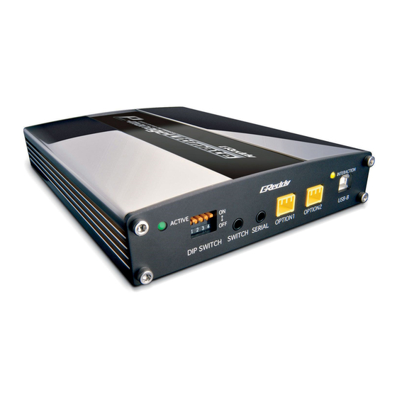
• Used with the Remote Switching System (sold separately) or Switching Harness (Sold separately). SERIAL • Used to link the GReddy Warning Meters with a Data Link Cable (sold separately) OPTION1,2 • Used to connect GReddy Pressure Sensor, GReddy Temp Sensor, and/or A/F Input Harness. -
Page 7: Initial Setup
JP10 Airflow Signal Input 2 / VTEC Output GT-R RB26DETT VTEC OUT 1 - 2 JP11 OPTION 1 Normal GReddy Temp Sensor OPEN JP12 OPTION 2 Normal GReddy Temp Sensor OPEN JP13 Knock Signal Input 1 / Water Temp Input... - Page 8 Initial Setup Jumper Setting Description JP1 Injector Input / Output Signal CH1 This jumper will configure the Injector Input / Output Signal CH1. Set to “OPEN” when using Injector Adj. Map to trim and add fuel, and set to “1-2” to add only. JP2 Injector Input / Output Signal CH2 This jumper will configure the Injector Input / Output Signal CH2.
- Page 9 OPTION 1 This jumper will configure the OPTION 1 port on the Front Panel of the unit. Set to “OPEN” for Normal type(when used for pressure or A/F sensor), and “1-2” when using GReddy Temp Sensor. JP12 OPTION 2 This jumper will configure the OPTION 2 port on the Front Panel of the unit.
-
Page 10: Initial Setup
Initial Setup Jumper Location When Jumping “1-2” or “2-3” make sure to match the pin numbers printed on the circuit board at the coresponding jumper locations. For “OPEN” make sure the jumper is not jumping the pins at the corresponding jumper locations. -
Page 11: How To Splice Wires
How to splice wires 1.Strip the wire as shown. 2.Wrap the stripped wire together as shown, and set the crimp in place. *Crimp is not neccessary if soldering. 4.wrap the connection with shrink tube or 3.Crimp or solder the connection. electrical tape. - Page 13 Wiring Power, Ground, Airflow Meter,Throttle, RPM Signal Hot-wire airflow meter, Flap type airflow meter, or Pressure sensor Gray (Throttle signal) White (Airflow Input 1) Connector B × Green (Airflow Output) Brown (rpm signal) Black (ECU Ground) Red (12v IG power) Female connector Male connector (Engine Control Unit)
-
Page 14: Wiring Power, Ground, Airflow Meter, Throttle, Rpm Signal 12~13
Wiring Power, Ground, Airflow Meter,Throttle, RPM Signal for RB26DETT (with 2 airflow meters) Gray (Throttle signal) White (Airflow Input 1) Yellow (Airflow Input 2) Connector B × × Green (Airflow Output) Brown (rpm signal) Black (ECU Ground) Red (12v IG power) Female connector Male connector (Engine Control Unit) -
Page 15: Vtec / Idle Control Valve
VTEC / Idle Control Valve for VTEC Equipped vehicle Yellow (VTEC output) × Light Blue (VTEC input) Connector B Cut and tape up × Purple (VTM output) Female connector Male connector Splice (Engine Control Unit) Idle Control Valve wiring (Engine Control Unit) Pulse Input (Light Blue) Connector B... -
Page 16: Injector Wires 15
10. Injector Signal Wires • Wire the injector signal wires for each cylinders. (except for Rotary Engines). • Normally, the Injector Adjustment will be set to add & trim (jumper JP1~6, 18 set to “OPEN”. Inj Adj. Map will be used to add and trim fuel). This can be set for add only. (jumper JP1~6, 18 set to “1-2”. - Page 17 Injector Signal Wires When changing I/J CH Example: Changing group injection to sequential injection Female connector (Engine Control Unit) Male connector How to connect Splice • Connect the necessary I/J CH OUT wires to the Connector C. Yellow/Red (I/J CH- 3 IN) •...
-
Page 18: Ignition Signal Wire 17
Ignition Signal Wire • Connect the e-manage Ignition channels in the engine’s firing order shown in the chart below. (Firing Order Chart) e-manage Channels 3, 4, 6, 8 cylinder Distributor 3 Cylinder Individual Ignition 4 Cylinder (Inline) Group Ignition t1,4 t2,3 4 Cylinder (Horizontally Opposed) Group Ignition t1,2... - Page 19 Ignition Signal Wire Distributer Type Ignition Honda Distributer (with 2 signal) Female Connector 26 pin connector Male Connector (Engine Control Unit) Splice Blue/White (IG CH-1 IN) × × Connector A Blue/White (IG CH-1 IN) Blue/Black (IG CH-1 OUT) *On Honda EG type vehicles, there are Connector A 2 ignition signals in the 26 pin connector.
-
Page 20: Analog Input, Output / Vehicle Speed Signal
Analog Input, Output / Vehicle Speed Signal Analog Input, Output wiring •These channels can be used on vehicels with airflow meter that uses a map sensor for boost limiter. (Factory contorlled boost cut or fuel cut) •Connect this wire to throttle or accelerator position sensor input, to change feedback range or A/T shift schedule. -
Page 21: 13. Crank & Cam Angle / Water & Intake Temp, Knock Signal
13. Crank & Cam Angle / Water & Intake Temp, Knock Signal Crank Angle Signal & Cam Angle Signal • Connect these wires for e-manage Ultimate to recognize the rpm signal from crank and cam angle signal if there are no tach signal out put from the ecu. Also. by connecting these wires Ignition timing can be monitored in the data log feature. -
Page 22: Nvcs / Relay Channels
NVCS / Relay Channels NVCS (Nissan Valve Control System) •Connecting one of these channels to the NVCS solenoid to control the NVCS. (Engine Control Unit) Cut and Connector B tape up Connect to desired channel NVCS Solenoid •Make sure the wire that was cut is taped up to prevent any short. •When using this feature the proper channels must be configured in the “I/J”... -
Page 23: Ecu Location Chart
ECU Location Chart Channel Symbol Description Crank Angle Signal Power RPM & Ignition Signal Cam Angle Signal & No. Ignition Signal Ground Leading Ignition Signal Intake Temp Siganl RPM Signal (F : front, C : Center, R : Rear) Water Temp Signal Throttle Signal Trailing Ignition Signal Knock Signal... -
Page 24: Ecu Wire Locationn Chart 23
ECU Wire Location Chart TOYOTA / LEXUS Chassis Engine Model Year Sensor Type CP # Code Code Location ARISTO SOARER SUPRA MARK 2 CELICA ALTEZZA IS300 LEVIN STARLET ESTIMA VITZ xA / xB ���� �� ����� ����������� ��� ��� �������� ���� ��������� ������ ����� �� ��� ������� ������� �������... - Page 25 ECU Wire Location Chart T 10 T 12 T 11...
- Page 26 ECU Wire Location Chart...
- Page 27 ECU Wire Location Chart...
- Page 28 ECU Wire Location Chart NISSAN / INFINITI Chassis Engine Model Year Sensor Type CP # Code Code Location SKYLINE G35 coupe CPV35 03 ~ 350Z 300ZX KA24DE SILVIA PULSAR ���� �� ����� ����������� ��� ��� �������� ���� ��������� ������ ����� �� ��� ������� ������� �������...
- Page 29 ECU Wire Location Chart...
- Page 30 ECU Wire Location Chart HONDA / ACURA Chassis Engine Model Year Sensor Type CP # Code Code Location CIVIC (Type-R) INTEGRA (Type-R) PRELUDE ACCORD ���� �� ����� ����������� ��� ��� �������� ���� ��������� ������ ����� �� ��� ������� ������� �������...
- Page 31 ECU Wire Location Chart *1 MT only Vehicle with VTM Signal...
- Page 32 ECU Wire Location Chart MITSUBISHI Chassis Engine Model Year Sensor Type CP # Code Code Location LANCER 3000GT ECLIPSE (2.4L) (3.0L V6) D53 M/T D53 A/T ���� �� ����� ����������� ��� ��� �������� ���� ��������� ������ ����� �� ��� ������� ������� �������...
- Page 33 ECU Wire Location Chart...
- Page 34 ECU Wire Location Chart MAZDA Chassis Engine Model Year Sensor Type CP # Code Code Location COSMO MIATA ���� �� ����� ����������� ��� ��� �������� ���� ��������� ������ ����� �� ��� ������� ������� �������...
- Page 35 ECU Wire Location Chart #RP #CP #FP #RP #FP MA 1 #RS #CS #FS #RS #FS MA 2 t F T #1 4 MA 3 MA 4 #2 3 t1 4 MA 5 t2 3 I tL MA 6 t1 4 #1 3 I tL MA 8...
- Page 36 ECU Wire Location Chart SUBARU Chassis Engine Model Year Sensor Type CP # Code Code Location ������ ������� �������� ���� �� ����� ����������� ��� ��� �������� ���� ��������� ������ ����� �� ��� ������� ������� �������...
- Page 37 ECU Wire Location Chart #1 #2 #1 #2 t1 2 t3 4 t1 2 t3 4...
- Page 38 Notes...
- Page 39 Notes...
Need help?
Do you have a question about the e-manage ultimate and is the answer not in the manual?
Questions and answers