
Related Manuals for QSC BASIS 904zz


Summary of Contents for QSC BASIS 904zz
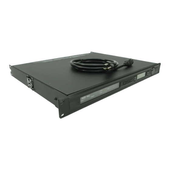
- Page 1 BASIS 904zz 16 Output CobraNet Enabled Control and Monitoring Signal Processor Hardware Manual *TD-000152-00* TD-000152-00 rev.A...
- Page 2 - Consult the dealer or an experienced radio or TV technician for help. © Copyright 2004 QSC Audio Products, Inc. QSC® is a registered trademark of QSC Audio Products, Inc. “QSC” and the QSC logo are registered with the U.S. Patent and Trademark Office. All trademarks are the property of their respective owners.
- Page 3 32 CobraNet channels on the network. Unlike many configurable DSP boxes, the intrinsic process- ing latency of the BASIS 904zz is both short and fixed at 0.396 milliseconds. The delay does not change regardless of the DSP configuration, unless the configuration intention- ally adds more delay.
- Page 4 DSP-30. The BASIS 904zz brings all that technology together in one compact, powerful, easy to use system. We are confident that your new BASIS 904zz will provide years of dependable service and we hope it will help you, the sys- tem designer and implementer, to express your creative audio system ideas.
- Page 5 The BASIS 904zz supports two distinct kinds of network activity; the first is audio transport via CobraNet, and the second is control and monitoring via QSControl.net. The user can choose to install one network for CobraNet traffic and a second separate network for QSControl traffic.
- Page 6 This applies primarily to existing CM16a and RAVE networks. For this very reason we continue to support connectivity to network repeater hardware with the BASIS 904zz. Support for network repeaters exist only with the Two Wire Interface. That is to say that the QSControl port and the CobraNet port must be connected to separate repeater LANs.
- Page 7 CobraNet ports of each unit. No network switch is required. This connection allows audio to pass between the two units over Cobra- Net. The BASIS 904zz is an audio “destination” device, therefore, the other unit must be an audio “source” device puting CobraNet audio data onto the cable.
- Page 8 Example #3 - Single Wire Interface: Here all QSControl and CobraNet traffic shares the same single CAT-5 cable between the BASIS 904zz and an unmanaged Ethernet switch. The QSControl.net system manages traffic flow efficiently and reliably so that all audio and control data is delivered to its appropriate destination anywhere on the network.
- Page 9 Example #4 - Two-Wire Interface (shared network hardware): This example illustrates the Two-Wire Interface with a managed Ethernet switch. The switch is configured with multiple virtual local area networks (VLANs). Ethernet deliveries can only reach destination ports belonging to the same VLAN from which it was sourced.
- Page 10 Example #5 - Two-Wire Interface (separate network hardware): Example #5 is conceptually similar to example #4. The difference here is that separate networks are created by providing each local area network (LAN) with its own network switch. Therefore, traffic segmentation is physical rather than logical. Example #5 also pro- vides an additional level of fault tolerance, although at the expense of additional network hardware.
-
Page 11: Rack Mounting
5-pin terminal block connector Mounting The BASIS 904zz can be used in or out of an equipment rack. Rack mounting is optional. Adhesive rubber feet are included for non-rack mount installations. Use them to prevent the unit from scratching or marring support surfaces. - Page 12 Computer Requirements & Software Installation Installing QSControl.net is easy. All you need to do is choose the folder where the program is to be stored (the default setting is accept- able for most applications). We recommend your system meet the following minimum requirements: 1- IBM PC compatible computer with a Pentium 4 processor.
-
Page 13: Amplifier Setup
Configuration Memories The BASIS 904zz has non-volatile storage locations that contain settings for the device as well as DSP signal flow. The storage loca- tions make it possible to set up the BASIS for different situations and quickly recall the setup with or without QSControl.net software... - Page 14 AC Power Cord Insert the molded receptacle of the AC power cord into the AC power inlet on the back of the BASIS 904zz. Plug the AC line con- nector into the AC outlet. The power supply will accept from 100 to 240 Volts AC, 47 to 440 Hertz, without any changes.
-
Page 15: Led Indicators
COM port on your PC and communicate using a terminal control program such as Windows Hyperterminal. Use a normal serial data cable with a DB-9 male plug to connect to the BASIS 904zz. To con- nect the cable, orient the connector properly, then push into the receptacle until it is firmly seated;... -
Page 16: Lcd Display And Controls
LCD Display and Controls The BASIS 904zz has a 2 line X 16 character LCD display. The display and the multi-function push-button switches on either side provide data access and editing capability. The push-button switches on either side of the display are used to navigate through the menus. - Page 17 LCD Navigation Map (typical) Left side buttons have screen dependent functions. This read-only screen is the “out of the box” default dis- play after power up. This is the most desired information when first setting up a net- work system. Once user moves to a different screen, the last screen accessed becomes the new power up...
-
Page 18: Getting Started
2- Connect a CAT-5 crossover cable from the computer’s network interface card (NIC) to the BASIS QSControl jack (example 1, page 6). 3- Reconnect the power cord to the BASIS 904zz (turn it on). Using the BASIS LCD display and controls, navigate the menu to the IP Address and make a note of it. - Page 19 Subnet masks are set correctly, and verify AC power is properly applied to the BASIS. 19- Click on the BASIS 904zz in the inventory root. A view of applicable device tabs will open. Click the DSP tab and the current DSP configuration of the BASIS will be displayed.
-
Page 20: Operation
24 may be selected to forward to the signal processing chain (DSP engine). The BASIS 904zz will support the delivery of up to 32 channels via up to 4 outbound bundles (to the network). Of these 32 channels, up to 24 may be unique (processed individually... -
Page 21: Safe Mode Switch
If the BASIS 904zz operates in an unexpected way or is not responding to any communications after a new firmware file is uploaded to it, it is likely the file was corrupted during transfer. If this occurs, there is a “backup” program in the BASIS 904zz that will enable you to communicate with it. - Page 22 6) The Hyper Terminal main window will appear next, but blank. Type the letter “h” (for help) and then press the“Enter” key. This will prompt the BASIS 904zz to post its menu text. The “h” key is the Help prompt for the BASIS 904zz. A text menu will appear. This is sent by the BASIS 904zz and will detail your options and instructions for changing the address information.
-
Page 23: Telnet Access
Basic procedure for opening a Telnet session: 1- To open the Telnet session- Click Start, select Run, type “Telnet” followed by a space, then the IP address of the BASIS 904zz you want to communicate with in the text box and click OK. - Page 24 Standard CobraNet Latency 6.313 milliseconds 8 HD-15 dataport connections QSC DataPort cable, QSC p-n DPC-x (“x” designates cable length in feet) 1, 2, 3, 4, 5, 6, 10, and 20 ft., custom lengths available. 32.8 ft. (10 m) 5-pin "Phoenix Style" (a.k.a. "Euro Style") detachable terminal blocks...
- Page 25 Preliminary Specification Monitor Output Monitor Freq. Resp. 20Hz-20KHz Distortion (20Hz-20KHz) Noise Floor Output Impedance (nom) Output Load (min) Monitor Level Control Range (nom) Relay Outputs Connector Type Configuration Pinout Switching Capacity (nom) Logic Outputs Connector Type Configuration Pinout Omni Inputs Connector Type Configuration Pinout...
-
Page 26: How To Contact Qsc Audio Products
QSC Audio Products 3 Year Limited Warranty QSC Audio Products, Inc. ("QSC") guarantees its products to be free from defective material and / or workmanship for a period of three (3) years from date of sale, and will replace defective parts and repair malfunctioning products under this warranty when the defect occurs under normal installation and use - provided the unit is returned to our factory or one of our authorized service stations via pre- paid transportation with a copy of proof of purchase (i.e., sales receipt).
Need help?
Do you have a question about the BASIS 904zz and is the answer not in the manual?
Questions and answers