Table of Contents
Advertisement
Advertisement
Table of Contents

Related Manuals for STEELE PRODUCTS SP-GG350


Summary of Contents for STEELE PRODUCTS SP-GG350
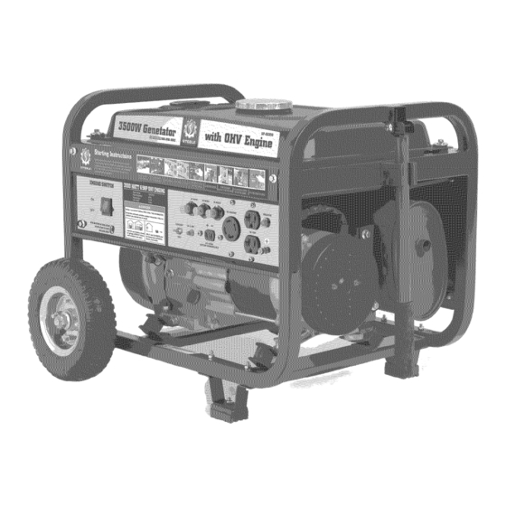
- Page 1 Owner's Manua! 350O SP-GG350 ton s_nvlcE CALL: 888-8964881 PARASERVICIO LLAME:...
- Page 2 DANGER Carbon Monoxide Using a generator indoors WiLL KiLL YOU iN MINUTES. Carbon Monoxide Generator exhaust contains high levels of carbon monoxide (CO), a poisonous gas you cannot see or smell. If you can smell the generator exhaust, you are breathing CO.
-
Page 3: Table Of Contents
3.5KW Generator Table of Contents Topic Page Safety Guidelines - Definitions General Precautions Assembly Specifications Installation Pre-Operation Check Operation Inspection, Cleaning, and Maintenance Compliance Maintenance Schedule Transporting/Storage Limited Warranty Parts Listing WARNING! READ AND UNDERSTAND ALL SAFETY PRECAUTIONS IN THIS MANUAL BEFORE OPERATING. FAILURE TO COMPLY WITH INSTRUCTIONS IN THIS MANUAL COULD RESULT IN PERSONAL INJURY,... -
Page 4: Safety Guidelines - Definitions
Owner'sManual Safety Guidelines- Definitions This manual contains important information that you need to know and understand in order to protect YOUR SAFETY and to PREVENT EQUIPMENT PROBLEMS. The following symbols help you recognize this information. Please read the manual and pay attention to these sections. WARNINGJWARNINGSINDICATE A CERTAINTY OR STRONG POSSIBILITY OF PERSONALINJURYOR DEATHIF INSTRUCTIONS ARE NOTFOLLOWED. - Page 5 3.5KWGenerator Carbon Monoxide When this tool is running, ensure that the area is well ventilated. Never run the engine in an enclosed area. Run the engine in an open area or with an exhaust evacuation system in an enclosed area. WARNING!THE EXHAUSTCONTAINSPOISONOUS CARBON MONOXIDE GAS THATCAN CAUSELOSS OFCONSCIOUSNESS AND MAY LEADTO DEATH.
- Page 6 Owner'sManual General Precautions (cont'd) Gasoline and Oil (cont'd) Excessive buildup of unburned fuel gases in the exhaust system can create a potentially explosive condition. This buildup can occur after repeated failed start attempts, valve testing, or hot engine shutdown. If this occurs, open exhaust system drain plugs, if equipped, and allow the gases to dissipate before attempting to restart the generator.
- Page 7 3.5KWGenerator • Grounded tools must be plugged into an outlet properly Electrical Safety installed and grounded in accordance with all codes and ordinances, Never remove the grounding prong or modify the plug in any way, Do not use any adapter plugs, •...
- Page 8 Owner's Manual General Precautions (cont'd) Electrical Safety (cont'd) Before servicing equipment powered by the generator, disconnect the equipment from its power input. Keep all electrical equipment clean and dry. Replace any wiring where the insulation is cracked, cut abraded or otherwise degraded. Replace terminals that are worn, discolored, or corroded.
- Page 9 3.5KWGenerator General Precautions(cont'd) GeneratorUse andCare • Make sure the power switch is in its "OFF" position and disconnect the spark plug wire before making any adjustment, changing accessories, or Storing the generator. Such preventive safety measures reduce the risk of starting the generator accidentally. •...
- Page 10 Owner's Manual General Precautions (cont'd) Installation Ensure installation meets all applicable safety, and local and national electrical codes. The installation performed by a qualified, licensed electrician and building contractor. All electrical work, including the earth-ground connection, should be completed by a licensed electrician. All separate fuel storage or generator supply facility must be built or installed in full compliance with all relevant local, state, and federal regulations.
- Page 11 3.5KWGenerator General Precautions (cont'd) Mechanical Always make sure the power switch is in its "OFF" position. Disconnect the spark plug wire, and allow the engine to completely cool before carrying out maintenance. Check for damaged parts. Before using the generator, any part that appears damaged should be carefully checked to determine that it will operate properly and perform its intended function.
- Page 12 Owner's Manual General Precautions (cont'd) Noise Prolonged exposure to noise levels above 85 dB is hazardous to hearing. Always wear ANSI approved ear protection when operating or working around the Generator when it is running. Extension Cord If an extension cord (not included) is used, make sure to use only UL approved...
-
Page 13: Assembly
3. KW Gen rator Assembly Unpacking 1. Remove the generator and loose parts box from the carton. 2. Compare the accessory with the inventory list below. Loose Parts (Wheel kit and handle) Check all loose parts against the following list. Contact your dealer toll free at 888.896.6881 if any of the loose parts shown are not included with your generator Hardware Check: Your Hardware... - Page 14 Own r's Manual Assembly Handle Installation. Start by installing the handle on the frame with two 8mm bolts. Then install the handle retainer shown. Floor Mount Instalation This generator has an option of not using the mobility kit. If this is desired, just install the 4 rubber mounts on the frame as shown.
- Page 15 Generator Assembly Wheel Kit Installation Here is the hardware required to install Start by installing the rubber floor mounts the support leg. Place a block of wood under the generator so that you don't onto the support teg as shown. have to hold it up while trying to install the teg.
-
Page 16: Specifications
Owner's Manual Specifications AC electrical Current output 120/240VAC @ 25/12.5A, 60Hz Continuous/rated wattage 3,000 Peak wattage 3,500 Outlets Two 120 VAC, 3- spring grounded One 120/240 VAC, twist lock, 4- sprin_ _rounded DC electrical Current output 12VDC @8.3A Gasoline engine Horsepower 6.5 HP Type... -
Page 17: Installation
3.5KW Generator Installation Note. Prior to powering tools and equipment, make sure the generator's rated voltage, wattage, and amperage capacity (two 120V-25AMPs outlets/one 240V- 12.SAMPs outlet) is adequate to supply all electrical loads that the unit willpower./fpowering exceeds the generator's capacity, it may be necessary to group one or more of the tools and/or equipment for connection to a separate generator. - Page 18 Owner's Manual Installation (cont'd) Support and Mounting Mount the generator on a concrete slab capable of supporting the weight of the generator. The slab must extend on all sides beyond the flame by at least one foot. Contact a cement contractor for slab specifications if necessary.
-
Page 19: Pre-Operation Check
3.5KW Generator PRE-OPERATION CHECK Fuel Recommendation 1. Check the fuel level gauge. 2. Refill the tank if the fuel level is low. Do not fill above the shoulder of the fuel strainer. Gasoline is extremely flammable and is explosive undei"certain conditions. -
Page 20: Operation
Owner's Manual Operation Note. The parts//stings above are he/pful for/ocating the contro/s mentioned below. CAUTION." PRIOR TO FIRST USING THE GENERA TOR, THE ENGINE MUST BE FILLED WiTH APPROX/MA TEL Y ¾ (0. 63) QUAR T OFA HiGH QUALITY SAE 10W-30 GRADE ENGINE OiL. - Page 21 3.5KW Generator Operation Operation Panel © 1. Engine Switch To start engine turn switch to "ON" position; To stop engine turn switch to "OFF" position 2. Voltage Selector Switch Switch to your desired voltage 120V or 240V before you connect your equipment.
- Page 22 Owner's Manual Operation (cont'd) Starting 1 Make sure the electrical powered tools/equipment that will be used are not plugged into the generator while the engine is started. 2 Open the fuel valve 3 Close the choke lever to about 1/8" clearance. 4Turn the engine power switch to ENGINE S_ its "ON"...
- Page 23 3.5KWGenerator Operation Powering 120/240Volt AC Tools And Equipment: 1 Prior to powering tools and equipment, make sure the generator's rated voltage, and amperage capacity (two 120V-25AMPs out/ets/one 240V- 12.SAMPs out/et) is adequate to supply all electrical loads that the unit will power. If powering exceeds the generator's capacity, it may be necessary to group one or more of the tools and/or equipment for connection to a separate generator.
- Page 24 Owner's Manual Inspection, Cleaning, and Maintenance WARNING!ALWAYSMAKE SURE THE ENGINEPOWERSWITCHIS IN ITS "OFF" POSITION.DISCONNECTTHE SPARK PLUG WIREFROM THEENGINE.AND ALLOW SUFFICIENTTIMEFOR THE ENGINEAND GENERATOR TO COMPLETEL Y COOL BEFOREPERFORMINGANY INSPECTIONS,MAINTENANCE,OR CLEANING. Before each use, inspect the generator. Check for: Loose screws Misaligned or binding moving parts Cracked or broken parts Damaged electrical wiring...
- Page 25 3.5KW Generator (Be fit for t he Generators with C ARBapproved.) inspection, Cleaning, and Maintenance • Spark arrestor maintenance: 1) unscrew screw from the end of muffler. 2) Remove the spark arrestor. 3) Use a wire brush to remove carbon deposits from spark arrestor screen If the generator has been running, the muffler will be very hoL Allow it to cool before proceeding.
-
Page 26: Compliance
Owner's Manual Compliance Manufacturer:JIANGSU JIANGDONG GROUP CO. LTD. Engine Family:8JDGS.1961GA Certificate Number:JDG-NRSI-08-04 FELs: g/kW-hr HC+NOx: Effective Date: 1/7/2008 Date Issued: 1/7/2008 Karl J. Simon, Director Compliance and Innovative Strategies Division Office of Transportation and Air Quality Pursuant to Section 213 of the Clean Air Act (42 U.S.C. section 7547) and 40 CFR 90, and subject to the terms and conditions prescribed in those provisions, this certificate of conformity is hereby issued for the following small nonroad engine family, more fully described in the documentation required by 40 CFR 90 and... -
Page 27: Maintenance Schedule
3.5KW Generator Periodic maintenance and adjustment is necessary to keep the generator in good operating condition, Perform the service and inspection at Me intervals shown in the Maintenance schedule below. _haust gas contains poisonous carbon monoxide. Shut off the engine before performing any maintenance, if the engine must be run, make sure the area is well ventilated, [ NOTICE J Use only genuine... - Page 28 Owner's Manual MAINTENANCE Air cleaner service A dirty air cleaner will restrict air flow to the carburetor. To prevent carburetor malfunction, service the air cleaner regularly. Service more frequently when operating the generator in extremely dusty areas. Using gasoline or flammable solvent to clean the filter element can cause a fire or explosion.
- Page 29 3.5KW Generator MAINTENANCE Fuel Sediment Cup Cleaning The sediment cup prevents dirt or water which may be in the fuel tank from entering the carburetor. If the engine has not been run for a long time, the sediment cup should be cleaned. 1.
- Page 30 Owner's Manual MAINTENANCE Spark Plug Service Recommended spark plugs: W20EPR-U (NIPPONDENSO) To ensure proper engine operation, the spark plug must be properly gapped and free of deposits. If the engine has been running, the muffler will be very hot. Be careful not to touch the muffler.
-
Page 31: Transporting/Storage
3.5KW Generator TRANSPORTING/STORAGE When transportingthe generator, turn the engine switch and the fuel valve OFF. Keep the generator level to prevent fuel spillage, Fuel vapor or spilled fuel may ignite. Contact with a hot engine or exhaust system can cause serious burns or fires. - Page 32 Owner's Manual TRANSPORTING/STORAGE 1. Drain the carburetor by loosening the drain screw. Drain the gasoline into a suitable container. Gasoline is extremely flammable is explosive under certain conditions Perform this task in awell ventilated area with the engine stopped. Do not smoke or allow flames or sparks in the area during this DRAIN SCRE 2.
-
Page 33: Limited Warranty
3.5KW Generator Limited Warranty STEELE® warrantsto the originalpurchaser who usesthe productin a consumerapplication(personal,residential o r householdusage)that all productscoveredunderthis warrantyare free from defectsin materialand workmanship for one yearfrom the dateof purchase.All productscovered by this limitedwarrantywhich are usedin commercial a pplications(i.e. incomeproducing)are warrantedto be free of defectsin materialand workmanship for 90 daysfrom the dateof originalpurchase.Products coveredunderthiswarrantyincludeair compressors, a ir tools,service parts,pressurewashers,and generators. - Page 34 Owner's Manual Limited Warranty (cont'd) THISWARRANTYDOESNOTCOVER: • Merchandise soldas reconditioned, u sedas rentalequipment,or flooror displaymodels. • Merchandise that has becomedamagedor inoperative becauseof ordinarywear,misuse,cold, heat,rain,excessivehumidity, f reeze damage,use of improperchemicals,negligence, a ccident,failureto operatethe productin accordance with the instructionsprovidedin the OwnersManual(s) suppliedwith the product,impropermaintenance, t he useof accessoriesor attachments not recommended bySTEELE®, or unauthorized repairor alterations.
- Page 35 3.5KW Generator Limited Warranty • ANY INCIDENTAL, INDIRECT OR CONSEQUENTIAL LOSS, DAMAGE, OR EXPENSE THAT MAY RESULT FROM ANY DEFECTS, FAILURE OR MALFUNCTION OF THE PRODUCT IS NOT COVERED BY THISWARRANTY. Some states do not allow the exclusion, so it maynot apply to you.
-
Page 36: Parts Listing
Owner's Manual PARTS LISTI NG... - Page 37 3500W Generator Cylinder head system assy. APA Part No. Descri tion Part. No SP-GG350-A-01-JD CYLINDER HEAD COMP. JF200-A-01 SP-GG350-A-02-JD EX. VALVE GUIDE JF168-A-02 SP-GG350-A-03-JD IN. VALVE GUIDE JF168-A-03 SP-GG350-A-04-JD VALVE GUIDE CLIP JF168-A-04 SP-GG350-A-05-JD CYLINDER HEAD SEALING JF200-A-05 SP-GG350-A-06-JD HEAD COVER COMP.
- Page 38 3500W Generator Cylinder barrel APA Part No. Descri tion Part. No SP-GG350-B-01-JD CRANK CASE JF200-B-01 SP-GG350-B-02-JD OIL LEVEL SWITCH ASSY. JF168-B-02 SP-GG350-B-03-JD GOVERNOR GEAR ASSY. JF168-B-03 SP-GG350-B-04-JD SLIDER SHAFT JF168-B-04 SP-GG350-B-05-JD GOVERNOR ARM SHAFT JF168-B-05 SP-GG350-B-06-JD JF168-B-06 LOCK PIN (8ram) SP-GG350-B-07-JD WASHER JF168-B-07...
- Page 39 3500W Generator Crankcase cover system assy. APA Part No. Descri tion Part. No SP-GG350-C-01 CRANKCASE COVER JF168-C-01 SP-GG350-C-02-JD CRANKCASE COVER JF168-C-02 SP-GG350-C-03-JD OiL SCALE JF168-C-03 SP-GG350-C-04-JD OiL SCALE SEAL JF168-C-04 SP-GG350-C-05-JD OiL SEAL(q)25Xq_41.25X8) JF168-C-05 SP-GG350-C-06-JD DOWEL PiN (8X 14) JF168-C-06 SP-GG350-C-07-JD FLANGE BOLT (M8X28)
- Page 40 3500W Generator Crankshaft system assy. APA Part No. Descri tion Part. No SP-GG350-D-OI-JD CRANKSHAFT COMP. JF200-D-01 SP-GG350-D-02-JD SEMICIRCLE JF168-D-02...
- Page 41 3500W Generator Piston and connecting rod system assy. APA Part No. Descri tion Part. No SP-GG350-E-01-JD COMPRESSION RING A JF200-E-01 SP-GG350-E-02-JD COMPRESSION RING B JF200-E-02 SP-GG350-E-03-JD OIL RING A JF200-E-03 SP-GG350-E-04-JD OIL RING B JF200-E-04 SP-GG350-E-05-JD PISTON PIN CLIP JF200-E-05 SP-GG350-E-06-JD PISTON JF200-E-05...
- Page 42 3500W Generator Recoil starter system assy. APA Part No. Descri tion Part. No SP-GG350-F-01 PIVOT ADJUSTING JF168-F-01 SP-GG350-F-02-JD ROCKER ARM PIVOT JF168-F-02 SP-GG350-F-03-JD ROCKER JF168-F-03 SP-GG350-F-04-JD JF168-F-04 PIVOT BOLT (MS) SP-GG350-F-05-JD PUSH ROD GUIDE PLATE JF168-F-05 SP-GG350-F-06-JD PUSH ROD JF168-F-06 SP-GG350-F-07-JD VALVE LIFTER...
- Page 43 3500W Generator Recoil starter system assy. APA Part No. Descri tion Part. No SP-GG350-G-01-JD RECOIL STARTER ASSY. JF168-G-01 SP-GG350-G-02-JD SETTING SCREW JF168-G-02 SP-GG350-G-03-JD SPRING RETAINER JF168-G-03 SP-GG350-G-04-JD PLATEN SPRING JF168-G-04 SP-GG350-G-05-JD STARTER RATCHET JF168-G-05 SP-GG350-G-06-JD RETURN SPRING JF168-G-06 SP-GG350-G-07-JD RECOIL STARTER REEL JF168-G-07...
- Page 44 3500W Generator Fan cover system assy. APA Part No. Descri tion Part. No SP-GG350-H-01-JD FAN COVER COMP. JF168-H-01 SP-GG350-H-02-JD FLYWHEEL SIDE PLATE JF168-H-02 SP-GG350-H-03-JD SHROUD JF168-H-03 SP-GG350-H-04-JD AIR CLEANER SUPPORT JF168-H-04 SP-GG350-H-05-JD FLANGE BOLT (M6 X 12) JF168-H-05 SP-GG350-H-06-JD FLANGE BOLT (M6 X 16) JF168-H-06...
- Page 45 3500W Generator Carburetor system assy. APA Part No. Descri tion Part. No SP-GG350-1-01 CARBURETOR ASSY. JF200-1-01 B SP-GG350-1-02-JD CARBURETOR PAPER GASKET JF168-1-02 SP-GG350-1-03-JD CARBURETOR INSULATING PLATE JF200-1-03B SP-GG350-1-04-JD INTAKE PIPE GASKET JF168-1-04...
- Page 46 3500W Generator Flywheel system Assy. APA Part No. Descri tion Part. No SP-GG350-J-01-JD FLYWHEEL JF168-J-01A SP-GG350-J-02-JD FLANGE BOLT (M6 X 25) JF168-J-02 SP-GG350-J-03-JD COOLING JF168-J-03 SP-GG350-J-04-JD STARTER PULLEY JF168-J-04 SP-GG350-J-05-JD FLYWHEEL NUT (M16) JF168-J-05 SP-GG350-J-06-JD STOP SWITCH CORD JF168-J-06 SP-GG350-J-07-JD IGNITION COIL ASSY.
- Page 47 3500W Generator Control System Assy. APA Part No. Descri tion Part. No SP-GG350-M-01 CONTROL ASSY. JF168-M-01B SP-GG350-M-02-JD CONTROL BASE COMP. JF168-M-02B SP-GG350-M-03-JD CONTROL ADJUSTING SPRING JF168-M-03 SP-GG350-M-04-JD PAN SCREW M5X34JF168-M-04 SP-GG350-M-05-JD JF168-M-05 FLANGE BOLT (M6 X 14) SP-GG350-M-06-JD GOVERNOR SPRING JF168-M-06 SP-GG350-M-07-JD THROTTLE...
- Page 48 3500W Generator Muffler System Assy. APA Part No. Descri tion Part. No SP-GG350-N-01-JD MUFFLER STAY COMP. JD3000-N-01 SP-GG350-N-02-JD FLANGE BOLT (M8 X 40) JD3000-N-02 SP-GG350-N-03-JD FLANGE BOLT (M6 X 16) JD3000-N-03 SP-GG350-N-04-JD MUFFLER COMP. JD3000-N-04 SP-GG350-N-05-JD MUFF. OUTER PROTECTOR COMP. JD3000-N-05 SP-GG350-N-06-JD FLANGE...
- Page 49 3500W Generator Air cleaner APA Part No. Descri tion Part. No SP-GG350-O-01-JD AIR CLEANER COVER COMP JD3000-C-01 SP-GG350-O-02-JD AIR CLEANER ELEMENT JD3000-C-02 SP-GG350-O-03-JD FLANGE NUT (M5) JD3000-C-03 SP-GG350-O-04-JD AIR CLEANER SEPARATOR JD3000-C-04 SP-GG350-O-05-JD AIR CLEANER SEAL JD3000-C-05 SP-GG350-O-06-JD AIR CLEANER CASE COMP JD3000-C-06 SP-GG350...
- Page 50 3500W Generator Fuel tank system assy. APA Part No. Descri tion Part. No SP-GG350-P-01-JD FUEL FILLER CAP COMP JD3000-D-01 SP-GG350-P-02-JD FUEL FILTER JD3000-D-02 SP-GG350-P-03-JD FUEL TANK COMP. JD3000-D-03 SP-GG350-P-04-JD FUEL METER ASSY. JD3000-D-04 SP-GG350-P-05-JD FLAT SCREW JD3000-D-05 SP-GG350-P-06-JD FLANGE BOLT JD3000-D-06 SP-GG350-P-07-JD AIR DUCT WASHER...
- Page 51 3250W Generator Control box assy. APA Part No. Descri tion Part. No SP-GG350-Q-01-JD ENGINE SWITCH ASSY. JD3000-1-Q-01 SP-GG350-Q-02-JD CONTROL PANEL COMP. JD3000-1-Q-02 SP-GG350-Q-03-JD VOLTAGE SWITCH JD3000-1-Q-03 SP-GG350-Q-04-JD OIL ALERT LAMP JD3000-1-Q-04 SP-GG350-Q-05-JD DC 12V OUTPUT JD3000-1-Q-05 SP-GG350-Q-06-JD 120V/240V RECEPTACLE JD3000-1 -Q-06 SP-GG350-Q-07-JD 120V RECEPTACLE JD3000-1 -Q-07...
- Page 52 3500W Generator Frame Comp assy. SP-GG350-R-01-JD FUEL TANK MOUNTING BOLT JD3000-R-01 SP-GG350-R-02-JD FRAME COMP. JD3000-1 -R-02 SP-GG350-R-03-JD JD3000-R-03 FLANGE BOLT SP-GG350-R-04-JD JD3000-R-04 FLANGE NUT ML._ SP-GG350-R-05-JD JD3000-R-05 MOTOR MOUNT (LEFT) SP-GG350-R-06-JD JD3000-R-06 FLANGE NUT (M8) SP-GG350-R-07-JD JD3000-R-07 FLANGE NUT (M10) SP-GG350-R-08-JD RUBBER FOOT...
- Page 53 3500W Generator Generator 19 11 APA Part No. Descri tion Part. No SP-GG350-S-01 STATOR COVER JD3000-S-01 SP-GG350-S-02-JD STATOR ASSY. JD3000-S-02 SP-GG350-S-03-JD COOLING JD3000-S-03 SP-GG350-S-04-JD BRUSH ASSY. JD3000-S-04 SP-GG350-S-05-JD TAPPING SCREW JD3000-S-05 SP-GG350-S-06-JD GENERATOR STAY JD3000-S-06 SP-GG350-S-07-JD JD3000-S-07 NUT _ SP-GG350-S-08-JD JD3000-S-08 FLANGE BOLT (M6X155)
- Page 54 3500W Generator Generator APA Part No. De scri tion Part. No SP-GG350-S-17-JD HEX.BOLT (M5 X 20) JD3000-S-17 SP-GG350-S-18-JD VOLT CHANGE TERMINAL BR-AC-W JD3000-S-18 JD3000-S-19 SP-GG350-S-19-JD PLAIN WASHER...
- Page 55 3500W Generator Wheel arid hand assy. /12 _ )/12 12 _8 APA Part No. Descri tion Part. No SP-GG350-T-01-JD COTTER JD3500-T-01 SP-GG350-T-02-JD PLAIN WASHER JD3500-T-02 SP-GG350-T-03-JD WHEEL JD3500-T-03 SP-GG350-T-04-JD AXLE HOLDER JD3500-T-04 SP-GG350-T-05-JD AXLE JD3500-T-05 SP-GG350-T-06-JD JD3500-T-06 FLANGE BOLT_ SP-GG350-T-07-JD JD3500-T-07 FLANGE SP-GG350-T-08-JD...
- Page 56 3500W Generator Wheel and hand assy. APA Part No. Descri tion Part. No SP-GG350-T-18-JD BRACKET JD3500-T-18 SP-GG350-T-19-JD BRACKET JD3500-T-19 16273 E. Gale Ave. City Of Industw, CA 91745 www.steele-products.com all rights reserved...
Need help?
Do you have a question about the SP-GG350 and is the answer not in the manual?
Questions and answers