
Related Manuals for STEELE PRODUCTS SP-GG1000E


Summary of Contents for STEELE PRODUCTS SP-GG1000E
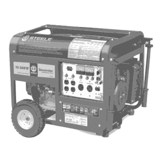
- Page 1 Owner's Manual Generstor 10,000 iiiiii_ run sEnvxc_ c :888-898-8881 SP-GGIOOOE PARA SERVICIO LLAME:...
- Page 2 Topic Page Limited Warranty Safety Guidelines General Precautions Battery Assembly Operation Inspection, Cleaning and Maintenance Transporting/Storage Installation Compliance Specifications Parts List WARNING! READ AND UNDERSTAND ALL SAFETY PRECAUTIONS IN THIS MANUAL BEFORE OPERATING. FAILURE TO COMPLY WITH INSTRUCTIONS IN THIS MANUAL COULD RESULT IN PERSONAL INJURY, PROPERTY DAMAGE, AND/OR VOIDING OF YOUR WARRANTY.
- Page 3 Steele@ warrantsto the originalpurchaserwho usesthe productin a consumerapplication(personal, residential o r householdusage)thatall productscoveredunderthis warrantyarefree from defectsin material a ndworkmanship for oneyearfrom the dateof purchase. A ll productscoveredby this limited warrantywhich are usedin commercial a pplications(i.e. incomeproducing)arewarrantedto befree of defectsin material a ndworkmanship for 90 daysfrom the dateof original purchase.Productscoveredunder this warrantyincludeair compressors, a ir tools, serviceparts,pressurewashersandgenerators.
- Page 4 Merchandise sold by Steele@ which has beenmanufactured by andidentifiedas the productof another company,suchas gasolineengines. T he productmanufacturer's warranty,if any, will apply. ANYINCIDENTAL, INDIRECT ORCONSEQUENTIAL LOSS, D AMAGE, OREXPENSE T HATMAYRESULT FROM ANYDEFECTS, FAILURE ORMALFUNCTION OFTHEPRODUCT I S NOTCOVERED B YTHIS WARRANTY.
- Page 5 This manualcontainsimportantinformationthatyou needto knowandunderstandin orderto keepYOU SAFE andto PREVENT E QUIPMENT P ROBLEMS. Thefollowing symbolshelpyou recognize this information. Please readthe manual a ndpayattentionto thesesections. SaveTheseImportantSafetyinstructions! Readandunderstand all of thesesafety instructions. Be sure to retain them for future use. WARNING! Warnings indicate a certainty or strong possibility of personal injury or death if instructions are not followed.
- Page 6 Owner's Manua! Gener Precautions WARNING! Failure to follow these instructions can result in severe injury or death. DANGER! Carbon Monoxide Using a generator induurs WILL KILL YOU IN MINUTES. Carbon Monoxide Generator exhaust contains high levels of carbon monoxide (CO), a poisonous gas you cannot see or smell, If you can smell the generator exhaust, you are breathing CO, But even If you cannot smell the exhaust, you could be breathing CO, •...
-
Page 7: Hot Components
Donot smoke,or allow sparks,flamesor othersourcesof ignitionaroundthe engineandfuel tank. Fuel vaporsareexplosive. Keepgroundedconductiveobjects,suchas tools, awayfrom exposed, l ive electricalpartsand connections to avoidsparkingor arcing.Theseeventscould ignitefumes or vapors. Donot refill the fuel tank whilethe engineis runningor whilethe engineis still hot. Donot operatethe generatorwith knownleaksin thefuel system Excessive buildupof unburned fuel gasesin the exhaustsystemcancreatea potentiallyexplosivecondition. -
Page 8: Personal Safety
Avoidbodycontactwith groundedsurfacessuchas pipes,radiators,ranges,andrefrigerators.Thereis an increased risk of electricshockif your bodyis grounded. Donot exposegeneratorto rain or wet conditions.Waterenteringa generatorwill increase the risk of electricshock. Donot abusethe powercord. Keeppowercordsawayfrom heat,oil, sharpedges,or movingparts.Replace damagedpowercords immediately. D amaged powercords increasethe risk of electricshock. Whenoperatinga powertool outside,usean outdoorextensioncord marked"W-A"or "W". Theseextension cordsare ratedfor outdoor use,andreducethe risk of electricshock. - Page 9 Dressproperly.Do not wearlooseclothingor jewelry.Containlong hair. Keepyour hair,clothing,andgloves awayfrom movingparts.Looseclothes,jewelry,or long hair canbecaughtin movingparts. Avoidaccidental s tarting. Makesurethe powerswitchis in its "OFF"position,anddisconnect t he sparkplug wire whennot in use. Remove adjustingkeysor wrenchesbeforeturning the generatoron. A wrenchor a keythat is left attached to a rotatingpart of the generatormay resultin personalinjury.
-
Page 10: Heart Pacemakers
Whenservicinga generator,useonly identicalreplacement p arts.Followall appropriate instructionsin this manual.Useof unauthorized partsor failure to follow maintenance instructionsmaycreatea risk of electric shockor injury. Heart Pacemakers WARNING! People with pacemakers should consult their physician(s) before using this product. Electromagnetic fields in close proximity to a heart pacemaker could cause interference to or failure of the pacemaker. - Page 11 Check for damaged parts.Beforeusingthe generator,anypart that appearsdamaged shouldbecarefully checkedto determinethat it will operateproperlyandperformits intendedfunction.Checkfor alignmentand bindingof movingparts,any brokenpartsor mountingfixtures,andanyotherconditionthat mayaffect properoperationtechnician. Thegeneratoris designed with guardsfor protectionfrom movingparts.In anycase,caremuststill betaken to protect personnel a ndequipment f rom other mechanical h azards whenworkingaroundthe generator. Donot operatethe generatorwith safetyguardsremoved.
- Page 12 Ma.ua] Battery Assembly To start generator with electric start you will need a battery (not included). You can use a 12v lawn tractor battery with the following specifications:The dimensions are Wx7.5" Dx5" Hx7"(including terminals). A rated cranking amperage of 200. Terminals are regular, not reversed. Note: Using a battery not designed for this unit may void warranty.
-
Page 13: Hardware Check
Manua! Assembly Unpacking 1. Remove the generator and loose parts box from the carton. 2. Compare the loose parts with the inventory list below. Loose Parts (Wheel kit and handle) Check all loose parts against the following list. Contact your dealer toll free at 888.896.6881 if any of the loose parts shown are not included with your generator Hardware Check: Your Hardware Kit should include:... - Page 14 Manual Assembly HafldJeIflstaiJatiofl Install the handle bracket. Connect handle with the bracket.
- Page 15 Manual Assembly Wheel Kit InstalJation Here is the hardware required to install Start by installing the rubber floor mounts the support leg, Placea block of wood under the generator so that you don't onto the support leg as shown, have to hold it up while trying to install the leg, Placethe support leg under the Note: The leg should be installed on the...
-
Page 16: Before Starting The Generator
Electric Start ...... FueITank NOTE: The parts listed above are helpful for locating the controls mentioned below. CAUTION Prior to first using the generator, the engine must be filled with a high quality sae 10w-30 grade engine oil. To do so unscrew and remove the engine's oil dipstick located at the bottom of the engine crankcase. -
Page 17: Stopping Engine
Starting 1, Turn the engine switch to the ON position. The engine switch enables and disables the ignition system. Run_ OFF: To stop the engine. RUN: To run the engine. 2. The fuel valve is located between the fuel tank and the carburetor. Key St When the valve lever is in the ON position, fuel is allowed to flow from the fuel tank to the carburetor. - Page 18 Powering 120 Volt AC Tools And Equipment: 1. Prior to powering tools and equipment, make sure the generator's rated voltage, and amperage capacity (120V AC) is adequate to supply all electrical loads that the unit will power. If powering exceeds the generator's capacity, it may be necessary to group one or more of the tools and/or equipment for connection to a separate generator.
-
Page 19: Spark Plug Service
Spark PlugService In order to service the spark plug, you will need a spark plug wrench (commercially available). Recommended spark plugs: NHSP LD F7TC. To ensure proper engine operation, the spark plug must be properly gapped and free of deposits. 1. - Page 20 WARNING! Always make sure the engine power switch is in its "OFF" position. Disconnect the spark plug wire from the engine and allow sufficient time for the engine and generator to completely cool before performing any inspections, maintenance, or cleaning. Before each use, inspect the generator.
- Page 21 Air Cleaner Service A dirty air cleaner will restrict air flow to the carburetor. To prevent carburetor malfunction, service the air cleaner regularly. Service more frequently when operation the generator in extremely dusty areas. NOTE Never run the generator without the air filter.
- Page 22 When transposing the gene _ turn the engine switch and the fuel valve OFE Keep the generator level to prevent fuel spillage, Fuel vapor or spilled fuel may Contact with a hot engine or exhaust m can cause burns or fires. Let the engine cool before...
- Page 23 Owner's Henue! Transpor|ing/S|orege 1. Drain the carburetor by loosening the drain screw. Drain the gasoline into a suitable container. conditions Pe_orm this task in a well ventilated area with the engine stopped. Do not smoke or allow flames Or sparks in the area during this DRAIN...
-
Page 24: General Location
NOTE: Prior to powering tools and equipment make sure the generator's rated voltage, wattage and amperage capacity is adequate to supply all electrical loads that the unit will power. If powering exceeds the generator's capacity, it may be necessary to group one or more of the tools and/or equipment for connection to a separate generator. - Page 25 UNITED STATES ENVIRONMENTAL PROTECTION AGENCY,WASHINGTON, DC20460 2005 ModelYearCertificate of Conformity Manufacturer: J iangsuJiandongGroupCo.Ltd. CertificateNumber:JDG-NRSI-05-04 EffectiveDate:12/09/2005 DateIssued:12/09/2005 MerrylinZaw-Mon,Director,Compliance and InnovationStrategiesDivision,Officeof Transportation andAir Quality. Pursuantto Section213of CleanAir Act (42 U.S.C. s ection7547)and40 CFR90, andsubjectto the terms andconditionsprescribedin thoseprovisions,this certificateof conformityis herebyissuedfor the following small non-roadenginefamily, morefully describedin the documentation requiredby40 CFR90 and producedin the statedmodelyear.
-
Page 26: Gasoline Engine
5pecificalions AC Electrical 120V/240V AC @ 62.5/31.25A 60Hz Current Output 7,500 Rated Wattage Peak Wattage 10,000 Outlet 4-120V outlets, 3 spring grounded 1-120/240V twist-lock DCElectrical 8.3A Gasoline Engine Horsepower Type 4-cycle OHV air-cooled Recoil & Electric Start 420cc Displacement 0il Capacity 1.1 6 quart (1.1 liter) EPA approved Fuel... -
Page 27: Cylinder Headassy
Cylinder Headassy. APA Part No. Description Part. No SP-GGIOOOE-A-O1-JD HEAD COVER COMP. BOLT JF340-A-01 SP-GGIOOOE-A-O2-JD HEAD COVERWASHER COMP. JF340-A-02 SP-GG1000 E-A-O3-JD TUBE JF340-A-13 SP-GGIOOOE-A-O4-JD HEAD COVER COMP. JF340-A-04 SP-GGIOOOE-A-O5-JD HEAD COVER PACKING JF340-A-05 SP-GGIOOOE-A-O6-JD FLANGE BOLT (M10X 80) JF340-A-06 SP-GGIOOOE-A-O7-JD SPARK PLUG JF340-A-07 SP-GGIOOOE-A-OS-JD... - Page 28 Cylinder Headassy. @--7 APAPart No. Description Part. No SP-GGIOOOE-B-O1-JD FLANGE BOLT (M6X 14) JF340-B-01 SP-GGIOOOE-B-O2-JD OIL LEVEL SWITCH ASSY. JF240-B-02 SP-GGIOOOE-B-O3-JD O-RING JF240-B-03 SP-GGIOOOE-B-O4-JD FLANGE NUT JF340-B-02 SP-GGIOOOE-B-O5-JD CRANK CASE JF420-B-02 SP-GGIOOOE-B-O6-JD BALL BEARING (6207) JF340-B-04 SP-GG1000 E-B-O7-JD WAS HER(®8.3x ®17xl )) J F340- B-05 SP-GGIOOOE-B-OS-JD LOCK PIN (10 mm)
- Page 29 CrankcaseCover System Assy. APAPart No. Description Part. No SP-GGIOOOE-C-O1-JD DUCT COVER JD5OOO-A-01 SP-GGIOOOE-C-O2-JD FLANGE BOLT (MS X 35) JD5OOO-A-02 SP-GGIOOOE-C-O3-JD OIL SCALE JF340-C-O3B SP-GGIOOOE-C-O4-JD OIL SCALE SEAL JF340-C-02 SP-GG1000E-C-O5-JD OIL SEAL(® 35x®52xS) JF340-B-11 SP-GGIOOOE-C-O6-JD FLANGE BOLT (MSX35) JF390-C-01 SP-GGIOOOE-C-O7-JD CRANKCASE COVER JF340-C-O4B SP-GGIOOOE-C-OS-JD SLIDER SHAFT...
- Page 30 Crankshaft System Assy. Part. No APA Part No. Description SP-GG1000E-D-OI-JD CRANKSHAFT COMP. JF420-D-02 SP-GG1000E-D-02-JD BALANCER WEIGHT JF340-D-04...
- Page 31 Pistonand Connecting Rod System Assy. APAPart Ho. Description Part. Ho SP-GGIOOOE-E-01-JD COMPRESSION RiNG A JF420-E-01 SP-GGIOOOE-E-O2-JD COMPRESSION RiNG B JF420-E-02 SP-GGIOOOE-E-O3-JD OiL RiNG A JF420-E-03 SP-GGIOOOE-E-O4-JD OiL RiNG B JF420-E-04 SP-GGIOOOE-E-O5-JD PISTON PiN CLiP (20 mm) JF420-E-05 SP-GGIOOOE-E-O6-JD PISTON JF420-E-05 SP-GGIOOOE-E-O7-JD PISTON PiN JF420-E-06...
- Page 32 Recoil Starter System Assy. APA Part No. Description Part. No SP-GGIOOOE-F-O1-JD PIVOT ADJUSTING NUT JF340-F-01 SP-GGIOOOE-F-O2-JD ROCKER ARM PIVOT JF340-F-02 SP-GG1000E-F-O3-J D ROCKER ARM JF340-F-03 SP-GGIOOOE-F-O4-JD PIVOT BOLT (M8) JF340-F-04 SP-GGIOOOE-F-O5-JD PUSH ROD GUIDE PLATE JF340-F-05 SP-GGIOOOE-F-O6-JD ROD PUSH JF240-F-06 SP-GGIOOOE-F-O7-JD VALVE LIFTER JF240-F-07...
- Page 33 Recoil Starter System Assy. © © APA Part No. Description Part. No SP-GGIOOOE-G-O1-JD REOOIL STARTER ASSY. JF340-G-01 SP-GGIOOOE-G-O2-JD SETTING SOREW JF340-G-02 SP-GGIOOOE-G-O3-JD SPRING RETAINER JF340-G-03 SP-GGIOOOE-G-O4-JD PLATEN SPRING JF340-G-04 SP-GGIOOOE-G-O5-JD STARTER RATOHET JF340-G-05 SP-GGIOOOE-G-O6-JD RETURN SPRING JF340-G-06 SP-GGIOOOE-G-O7-JD REOOIL STARTER REEL JF340-G-07 SP-GGIOOOE-G-O8-JD REOOIL STARTER SPRING...
-
Page 34: Fan Cover System Assy
Fan Cover System Assy. © Part. No APA Part No. Description SP-GGIOOOE-H-O1-JD SHROUD JF340-H-01 SP-GGIOOOE-H-O2-JD JF340-H-02 FLANGE BOLT (M6 X 14) SP-GGIOOOE-H-O3-JD FAN COVER COMP. JF340-H-03 SP-GGIOOOE-H-O4-JD WIRE HARNESS CLIP JF340-H-04... - Page 35 Carburetor System Assy. APA Part No. Description Part. No SP-GGIOOOE-I-O1-JD TUBE CLIP JD3800-B-01 SP-GG1000E-1-O2-JD TUBE A JD3800-B-02 SP-GGIOOOE-1-O3-JD TUBE B JD3800-B-03 SP-GGIOOOE-1-O4-JD WIPE HARNESS CLIP JD3800-B-04 SP-GGIOOOE-1-O5-JD DASHPOT CHECK VALVE JD3800-B-05 SP-GGIOOOE-1-O6-JD MANUAL CHOKE STAY ASSY. JD3800-B-06 SP-GGIOOOE-1-O7-JD CARBURETOR IRON GASKET JF340-1-05 SP-GG1000E-1-O8-JD CARBURETOR ASSY.
-
Page 36: Flywheelsystem Assy
FlywheelSystem Assy. Part. No APA Part No. Description FLYWHEEL SP-GGIOOOE-J-O1-JD JF340-J-01 B SP-GGIOOOE-J-O2-JD SPEOIAL WOODRUFF KEY JF340-J-02 SP-GGIOOOE-J-O3-JD O00LING FAN JF340-J-03 SP-GGIOOOE-J-O4-JD STARTER PULLEY JF340-J-04 SP-GGIOOOE-J-O5-JD JF340-J-05 FLYWHEEL NUT (M16) - Page 37 ignition System Assy. APA Part No. Description Part. No SP-GGIOOOE-K-O1-JD SPARK PLUG CAP ASSY. JF340-K-01 SP-GGIOOOE-K-O2-JD INGITION GOIL ASSY. JF340-K-02 SP-GGIOOOE-K-O3-JD STOP SWITCH CORD JF340-K-03 SP-GGIOOOE-K-O4-JD STOP SWITCH CORD HOLDER JF340-K-04 SP-GGIOOOE-K-O5-JD FLANGE BOLT (M6 X 25) JF340-K-05 SP-GGIOOOE-K-O6-JD CORD GROMMENT JF340-K-06 SP-GGIOOOE-K-O7-JD CHARGE COIL ASSY.
- Page 38 Starter Motor System Assy.. Part. No APA Part No. Description SP-GGIOOOE-L-O1-JD STARTER MOTOR JF340-L-01 SP-GGIOOOE-L-O2-JD SOLENOID JF340-L-02 SP-GGIOOOE-L-O3-JD JF340-L-03 FLANGE BOLT (M8x35)
-
Page 39: Controlsystem Assy
ControlSystem Assy. APAPart No. Description Part. No SP-GGIOOOE-M-O1-JD CONTROL ASSY. JF340-M-01B SP-GGIOOOE-M-O2-JD CONTROL BASE COMP. JF340-M-O2B SP-GGIOOOE-M-O3-JD CONTROL ADJUSTING JF340-M-03 SP-GGIOOOE-M-O4-JD PAN SCREW (M5 X 34) JF340-M-04 SP-GGIOOOE-M-O5-JD FLANGE BOLT (M6 X 14) JF340-M-05 SP-GGIOOOE-M-O6-JD GOVERNOR SPRING JF340-M-06 SP-GGIOOOE-M-O7-JD THROTTLE RETURN SPRING JF340-M-07 SP-GGIOOOE-M-OS-JD GOVERNOR ROD... - Page 40 iVlufflerSystem Assy. Part. No APA Part No. Description SP-GGIOOOE-N-O1-JD JD3800-B-01 FLANGE BOLT (M8 X 16) SP-GGIOOOE-N-O2-JD JD3800-B-02 FLANGE BOLT (M6 X 12) SP-GGIOOOE-N-O3-JD MUFFLER STAY COMP. JD3800-B-03 SP-GGIOOOE-N-O4-JD MUFFLER PROTECTOR SEAL JD3800-B-04 SP-GGIOOOE-N-O5-JD MUFFLER SIDE PROTECTOR JD3800-B-05 SP-GGIOOOE-N-OG-JD MUFF. INNER PROTECTOR COMP. JDSOOO-A-01 SP-GGIOOOE-N-O7-JD JDSOOO-A-02...
-
Page 41: Air Cleaner
Air Cleaner o_° ® Part. No APA Part No. Description SP-GGIOOOE-O-O1-JD AIR CLEANER COVER COMP JD3800-C-01 SP-GGIOOOE-O-O2-JD AIR CLEANER ELEMENT JD3800-C-02 SP-GGIOOOE-O-O3-JD JD3800-C-03 FLANGE NUT (M5) SP-GGIOOOE-O-O4-JD AIR CLEANER SEPARATOR JD3800-C-04 SP-GGIOOOE-O-O5-JD AIR CLEANER SEAL JD3800-C-05 SP-GGIOOOE-O-O6-JD AIR CLEANER CASE OOMP JD3800-C-06 SP-GGIOOOE-O-O7-JD GASKET... - Page 42 Fuel Tank System Assy. APAPart No. Part. No Description SP-GGIOOOE-P-OI-JD FUEL FILLER CAP COMP JD3800-D-01 SP-GGIOOOE-P-O2-JD FUEL FILTER JD3800-D-02 SP-GGIOOOE-P-O3-JD FUEL TANK COMP. JD3800-D-03 SP-GGIOOOE-P-O4-JD FUEL METER ASSY. JD3800-D-04 SP-GGIOOOE-P-O5-JD FLAT SCREW JD3800-D-05 SP-GGIOOOE-P-O6-JD FLANGE BOLT JD3800-D-06 SP-GGIOOOE-P-O7-JD AIR DUCT WASHER JD3800-D-07 SP-GGIOOOE-P-OS-JD TANK CUSHION WASHER...
-
Page 43: Control Box Assy
Control Box Assy Part. No APA Part No. Description SP-GGIOOOE-Q-O1-JD CONTROL PANEL COMP. JD8OOOE-E-01 SP-GGIOOOE-Q-O2-JD ENGINE SWITCH ASSY. JD6500BST-E-02 SP-GGIOOOE-Q-O3-JD DO 12V OUTPUT JD6500BST-E-03 SP-GGIOOOE-Q-O4-JD VOLTMETER ASSY. JD6500BST-E-04 SP-GGIOOOE-Q-O5-JD JD6500BST-E-05 120V RECEPTACLE(Ru-22) SP-GGIOOOE-Q-O6-JD CIRCUIT BREAKER 20A JD8OOOE-E-06 SP-GGIOOOE-Q-O7-JD JD6500BST-E-07 120V RECEPTACLE(L5-30) SP-GGIOOOE-Q-OS-JD JD6500BST-E-08 240V RECEPTACLE(L14-30) - Page 44 FrameComp Assy. APAPart No. Part. No Description SP-GGIOOOE-R-O1-JD FUEL TANK MOUNTING BOLT JD3800-F-01 SP-GGIOOOE-R-O2-JD FRAME COMP. JDSOOO-F-02 SP-GGIOOOE-R-O3-JD JO3800-F-03 FLANGE BOLT (aGX 12) SP-GGIOOOE-R-O4-JD JD3800-F-04 FLANGE NUT (a8) SP-GGIOOOE-R-O5-JD JD3800-F-05 MOTOR MOUNT (LEFT) SP-GGIOOOE-R-OG-JD JD3800-F-06 MOTOR MOUNT (RIGHT) SP-GGIOOOE-R-O7-JD JD3800-F-07 FLANGE NUT (MIO) SP-GGIOOOE-R-OS-JD JD3800-F-08...
- Page 45 Generator 18 20 19 \ lo APAPart No. Description Part. No SP-GGIOOOE-S-O1-JD STATOR COVER JD6500-D-01 SP-GGIOOOE-S-O2-JD STATOR ASSY. JD6500-D-02 SP-GGIOOOE-S-O3-JD COOLING FAN JD6500=G=03 SP-GGIOOOE-S-O4-JD BRUSH ASSY. JD3800=G=04 SP-GGIOOOE-S-O5-JD TAPPING SCREW JD3800-G=05 SP-GGIOOOE-S-OG-JD GENERATOR STAY JD3800-G=06 SP-GGIOOOE-S-O7-JD JD8OOO-G=08 FLANGE BOLT (MGX197) SP-GGIOOOE-S-OS-JD AUTO VOLTAGE REG.
- Page 46 Wheel & HandAssy. 1_(_ APAPart No. Description Part. No SP-GGIOOOE-T-O1-JD COTTER PIN JD6500-T-01 SP-GGIOOOE-T-O2-JD PLAIN WSHER JD6500-T-02 SP-GGIOOOE-T-O3-JD WHEEL JD8OOO-T-03 SP-GGIOOOE-T-O4-JD SHAFT JD8OOO-T-04 SP-GGIOOOE-T-O5-JD FLANGE BOLT JD6500-T-05 SP-GGIOOOE-T-O6-JD VIBRATION ABSORBER JD6500-T-06 SP-GGIOOOE-T-O7-JD FLANGE NUT (M8) JD6500-T-07 SP- GG10O0E-T-O8-JD STAND JD6500-T-08 SP-GGIOOOE-T-Og-JD FLANGE BOLT (M6X 16) JD6500-T-09...
Need help?
Do you have a question about the SP-GG1000E and is the answer not in the manual?
Questions and answers