Table of Contents
Advertisement
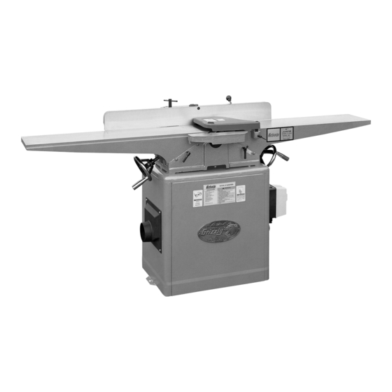
MODEL G0500/G1018/G1018HW
8" JOINTER
OWNER'S MaNuaL
Model G0500 Shown
Copyright © JANUAry, 2003 By grizzly iNdUstriAl, iNC., revised JUly, 2012 (tr)
WaRNING: NO pORTION Of THIS MaNuaL May bE REpRODucED IN aNy SHapE
OR fORM WITHOuT THE WRITTEN appROvaL Of GRIzzLy INDuSTRIaL, INc.
#tr4986 priNted iN tAiWAN
Advertisement
Table of Contents
Troubleshooting

Subscribe to Our Youtube Channel
Related Manuals for Grizzly G0500


Summary of Contents for Grizzly G0500
- Page 1 8" JOINTER OWNER'S MaNuaL Model G0500 Shown Copyright © JANUAry, 2003 By grizzly iNdUstriAl, iNC., revised JUly, 2012 (tr) WaRNING: NO pORTION Of THIS MaNuaL May bE REpRODucED IN aNy SHapE OR fORM WITHOuT THE WRITTEN appROvaL Of GRIzzLy INDuSTRIaL, INc.
- Page 2 This manual provides critical safety instructions on the proper setup, operation, maintenance, and service of this machine/tool. Save this document, refer to it often, and use it to instruct other operators. Failure to read, understand and follow the instructions in this manual may result in fire or serious personal injury—including amputation, electrocution, or death.
-
Page 3: Table Of Contents
TABLE OF CONTENTS PAGE SAFETY ............................3 Safety Instructions For Power Tools ..................3-4 Additional Safety Instructions For Jointers ................5 INTRODUCTION ..........................6 CIRCUIT REQUIREMENTS ......................7 220V Operation ........................7 110V Operation ........................8 Grounding ..........................9 Extension Cords ........................9 IDENTIFICATION ........................10-11 Common Terms and Definitions ..................11 SETUP ............................12 Unpacking ..........................12 G0500 Inventory ........................12... - Page 4 MAINTENANCE..........................34 General ..........................34 Table ............................34 Lubrication ..........................34 V-Belt............................34 Knife Condition ........................34 Maintenance Log........................35 SERVICE ADJUSTMENTS ......................36 About Service ........................36 Setting Knives ........................36-37 Adjusting Gibs ........................37-38 Adjusting V-Belt ......................38-39 Replacing V-Belt ........................39 Service Log ..........................40 REFERENCE INFO ........................41 Troubleshooting Guide ....................42-43 G0500/G1018/G1018HW Wiring Diagram ................44 G0500 Machine Data ......................45 G0500 Parts Breakdown and Parts List................46-51...
-
Page 5: Safety
SECTION 1: SAFETY For Your Own Safety Read Instruction Manual Before Operating This Equipment The purpose of safety symbols is to attract your attention to possible hazardous conditions. This manual uses a series of symbols and signal words which are intended to convey the level of importance of the safety messages. -
Page 6: Safety Instructions For Power Tools
Safety Instructions For Power Tools 9. USE PROPER EXTENSION CORD. Make 15. USE RECOMMENDED ACCESSORIES. sure your extension cord is in good condi- Consult the owner’s manual for recom- tion. Conductor size should be in accor- mended accessories. The use of improper dance with the chart below. -
Page 7: Additional Safety Instructions For Jointers
Like all power tools, there is danger asso- No list of safety guidelines can be complete. ciated with the Grizzly 8" Jointers. Every shop environment is different. Always Accidents are frequently caused by lack of consider safety first, as it applies to your familiarity or failure to pay attention. -
Page 8: Introduction
Model listed below. G0500/G1018/G1018HW. These 8" jointers are part of a growing Grizzly family of fine wood- Grizzly Industrial, Inc. working machinery. When used according to the 1203 Lycoming Mall Circle guidelines set forth in this manual, you can... -
Page 9: Circuit Requirements
SECTION 3: CIRCUIT REQUIREMENTS Circuit Breaker Requirements 220V Operation We recommend that the circuit you use your machine on should be dedicated. Because the machine motors are different sizes, please use the following guidelines when choosing a circuit Amperage Draw breaker for your machine (circuit breakers rated The Model G0500/G1018/G1018HW motors are any higher are not adequate to protect the cir-... -
Page 10: 110V Operation
110V Operation NOTICE Model G0500/G1018/G1018HW prewired for 220V operation. If you plan to rewire your machine for 110V, you must use a different switch. Consult a licensed electrician before attempting to rewire your machine! 110V Amperage Draw Figure 3. 5-20 plug and outlet. The Model G0500/G1018/G1018HW motors can be rewired for 110V if you use a different switch. -
Page 11: Grounding
If you find it absolutely necessary to use an dance with all local codes and ordinances. extension cord at 220V with your Grizzly 8" Jointer: • Make sure the cord is rated for Standard Verify that any existing Service (grade S) or better. -
Page 12: Identification
SECTION 4: IDENTIFICATION Figure 4. The following is a list of controls and components on the Model G0500/G1018/G1018HW. Please take time to become familiar with each item and its location. These items will be used throughout the man- ual and knowing them is essential to understanding the instructions and terminology used in this manual. Fence Lock ON/OFF Switch Fence... -
Page 13: Common Terms And Definitions
Figure 5. Fence controls. Figure 6. Cutterhead details. 17. 45˚L Stop Nut 23. Cutterhead 18. Fence Lock 24. Cutterhead Knife 19. Fence Tilt Lock 25. Gib Bolt 20. 45˚R Stop Bolt 26. Gib 21. 90˚ Stop Bolt 27. Jack Screw Access Hole 22. -
Page 14: Setup
SECTION 5: SET UP Unpacking G0500 Inventory • Jointer Assembly w/Fence ......1 The Grizzly 8" Jointers are shipped from the man- • Infeed Extension ........1 ufacturer in a carefully packed crate and a card- • Outfeed Extension ........1 board box. If you discover the machine is dam- •... -
Page 15: G1018 Inventory
G1018 Inventory G1018HW Inventory • Jointer Assembly w/Fence ......1 • Jointer Assembly w/Fence ......1 • V-Belt M52..........2 • V-Belt M52..........2 • Table Lever ..........2 • Handwheel..........2 • Hardware Bag #1 • Handle ............2 —Combo Wrench 8/10MM ......1 • Hardware Bag #1 —Combo Wrench 12/14MM ......1 —Combo Wrench 8/10MM ......1 —Allen Wrench 3MM ........1... -
Page 16: Hardware Recognition Chart
Hardware Recognition Chart Use this chart to match up hardware pieces during the assembly process! Lock Wing ⁄ Countersunk Thumb ⁄ Phillips Phillips Screw Slotted Head Head Screw Screw Screw ⁄ ⁄ ⁄ Carriage Button Flange Bolt Head Screw Bolt Screw ⁄... -
Page 17: Clean Up
Most commercial or vent cleaner or citrus-based degreaser such as garage shop floors should be sufficient to carry Grizzly’s G7895 Degreaser. To clean thoroughly, the weight. Before moving the jointer onto a res- some parts may need to be removed. For opti-... -
Page 18: Beginning Assembly
Beginning Assembly Switch Installation This section will cover the minimum assembly To install the switch: and adjustment instructions needed to begin operation. For best results, complete the assem- Locate the #10-24 x 1 ⁄ " Phillips head bly in the order provided in this manual and then screws that are included in the hardware bag read the remaining portion of the manual before with the switch. -
Page 19: Wiring Connection
Snap fit the grommet into the opening as Make the motor connections in accordance shown in Figure 12. Make sure there is with the wiring schematics that are located enough slack in the wire between the switch on the motor label or those shown below in and the grommet before snapping the grom- Figure 14 or Figure 15, depending on which met into position. -
Page 20: Jointer Stand
Jointer to Stand If you will be placing the jointer on a mobile base, set the stand on the mobile base before installing the jointer unit onto the stand. If you will be bolting the stand to the floor, posi- tion the stand in its proper location and secure it to the floor, using fasteners through the mounting flanges shown in Figure 16, before installing the... -
Page 21: V-Belt
Loosen the motor mount bolts shown in Place firm tension on the motor and tighten Figure 19. the motor adjustment bolts. Note—Only use your hands to place tension on the motor. DO NOT use a pry bar or any other device to place added leverage on the motor. -
Page 22: Fence To Jointer
Fence to Jointer G0500/G1018HW Handwheel Installation To install the fence on the jointer unit: To install the handwheels on the Model Place the fence on the jointer unit as it was G0500/G1018HW: before you removed it for clean up. Make sure the key on the fence support lines up Remove the screw and washer from the end with the keyway on the fence. -
Page 23: G1018 Table Lever Installation
G1018 Table Knife Setting Gauge Lever Installation To assemble the knife setting gauge: To install the table levers on the Model Insert the steel rod through the hole in each G1018HW: adjuster arm until the notches for the E-clips extend past the adjustment arms on both Thread a table lever into the adjustment sides. -
Page 24: Knife Inspection
Make sure that the middle pad of the jig is Knife Inspection barely touching the knife and that the pads on the ends of the jig are resting firmly on the cutterhead. The knives were set to their proper height at the Repeat step 5 on all knives. - Page 25 To adjust the infeed table: Make sure the outfeed table is adjusted as previously described. Place a straightedge half way on the outfeed table and halfway over the infeed table. Release the infeed table lock and adjust the infeed table flush with the outfeed table as illustrated in Figure 32.
-
Page 26: G1018 Table Stops
To set the Model G1018 infeed table stop bolt: G1018 Table Stops Make sure that the infeed table has been adjusted and that the pointer on the depth indicator scale has been calibrated as previ- The Model G1018 has table stop bolts (see ously described. -
Page 27: Cutterhead Guard
Lower the shaft into the shaft housing far Cutterhead Guard enough that the spring tang will rest against the edge of the infeed table when released, as shown in Figure 37. To install the cutterhead guard: Locate the spring tang on the cutterhead guard that is shown in Figure 35. -
Page 28: Fence Stops
If it does not, then the fence needs to be adjusted. The Grizzly 8" Jointers have three fence stops at Loosen the jam nut on the 45˚R fence stop 45˚ R, 90˚, and 45˚L (see Figure 39). It is impor- bolt. -
Page 29: Plug Installation
To check and adjust the 45˚L fence stop: Plug Installation Loosen the fence tilt lock handle. Using the tilt handle, slowly tilt the fence To install a plug on your power cord: toward the front of the jointer until it stops. Refer to Section 3: Circuit Requirements to Set your bevel gauge to 45˚, and place it on determine the correct plug and receptacle for... -
Page 30: Operations
SECTION 6: OPERATIONS Your safety is important! Please follow the Stock Inspection warnings below during this entire section: & Requirements Operating this equipment creates the potential for flying debris to cause eye Here are some rules to follow when choosing injury. -
Page 31: Squaring Stock
• Make sure that any stock you process with Squaring Stock the jointer is clean and free of any dirt, nails, staples, tiny rocks or any other foreign objects that may damage the jointer blades. The jointer performs two of the four required •... -
Page 32: Surface Planing
Make sure your workpiece is within the mini- mum and maximum stock dimensions that Figure 45. Surface planing the face of a your Grizzly 8" Jointer can safely process. workpiece. (Check the data sheet in the back of this manual for your particular model.) Set the cutting depth for your operation. -
Page 33: Edge Jointing
Make sure your workpiece is within the mini- mum and maximum stock dimensions that your Grizzly 8" Jointer can safely process. (Check the data sheet in the back of this manual for your particular model.) Set the cutting depth for your operation. (We suggest between ⁄... -
Page 34: Bevel Cutting
If your workpiece is cupped (warped), place The Grizzly 8" Jointers have preset fence stops at it so the concave side is face down on the 45˚ to the left and 45˚ to the right. If your situation surface of the infeed table. -
Page 35: Rabbet Cutting
Inspection” instructions earlier in this section. Make sure your workpiece is within the mini- mum and maximum stock dimensions that your Grizzly 8" Jointer can safely process. (Check the data sheet in the back of this manual for your particular model.) Figure 51. -
Page 36: Maintenance
The table and other non-painted surfaces on your A good maintenance procedure is to hone the Grizzly 8" Jointer should be protected against rust knives to keep them in top shape. A knife hone and pitting. Wiping the table clean after every use... -
Page 37: Maintenance Log
Maintenance Log Date Maintenance Performed Approximate Hours Of Use G0500/G1018/G1018HW 8" Jointers -35-... -
Page 38: Service Adjustments
*Note—If this is the first time you are setting the knives, remove the gib and knife from the The knives on your Grizzly 8" Jointer should be cutterhead. Decide which adjustment option set .051" (1.3MM)-.060" (1.5MM) higher than the you are going to use between the jack cutterhead. -
Page 39: Adjusting Gibs
the jack screws, remove the springs from the Springs—Push the knife down with the jig so cutterhead. If you decide to use the springs, that the knife edge is touching the middle you can just thread the jack screws com- pad of the jig. -
Page 40: Adjusting V-Belt
Adjusting V-Belts In order for your jointer to perform at its best, you should check (and adjust if necessary) the V-belt tension and alignment. To adjust the V-belt tension: Disconnect the jointer from the power source! Remove the stand door to gain access to the Figure 56. -
Page 41: Replacing V-Belt
Replacing V-Belt During the life of your jointer, you will need to replace the V-belts when they become cracked or damaged. To replace the V-belts: Disconnect the jointer from the power source! Remove the stand door to gain access to the Figure 58. -
Page 42: Service Log
Service Log Date Service Performed Approximate Hours Of Use -40- G0500/G1018/G1018HW 8" Jointers... -
Page 43: Reference Info
Warranty/Return information Grizzly's warranty and return policy. If you need for your Model G0500/G1018/G1018HW. additional technical information relating to this machine, or if you need general assistance or... -
Page 44: Troubleshooting Guide
TROUBLESHOOTING GUIDE SYMPTOM POSSIBLE CAUSE CORRECTIVE ACTION Motor will not start. 1. Low voltage. 1. Check power line for proper voltage. 2. Open circuit in motor or loose connec- 2. Inspect all lead connections on motor for loose or open connec- tions. -
Page 45: Troubleshooting Guide
TROUBLESHOOTING GUIDE SYMPTOM POSSIBLE CAUSE CORRECTIVE ACTION Lines or ridges in on board 1. Nicked or chipped knives. 1. Inspect and sharpen the cutterhead knives. Uneven knife marks on 1. One or more knives out of alignment. 1. Reset the knives in the cutterhead, using the knife setting jig. board See page 36-37. -
Page 46: G0500/G1018/G1018Hw Wiring Diagram
G0500/G1018/G1018HW Wiring Diagram -44- G0500/G1018/G1018HW 8" Jointers... -
Page 47: G0500 Machine Data
MACHINE DATA SHEET Customer Service #: (570) 546-9663 • To Order Call: (800) 523-4777 • Fax #: (800) 438-5901 MODEL G0500 8" X 75" JOINTER W/4-BLADE CUTTERHEAD Design Type: ......................Cabinet Overall Dimensions: Table Size....................9" W x 75" L Height (from floor to table) ..................31 ⁄... -
Page 48: G0500 Parts Breakdown And Parts List
G0500 29 30Ł 26 -46- G0500/G1018/G1018HW 8" Jointers... - Page 49 G0500 G0500/G1018/G1018HW 8" Jointers -47-...
- Page 50 G0500 -48- G0500/G1018/G1018HW 8" Jointers...
- Page 51 G0500 316A G0500/G1018/G1018HW 8" Jointers -49-...
- Page 52 PART # DESCRIPTION PART # DESCRIPTION 1 PG1018HW001 BASE 101 PG1018101 FENCE 2 P0500002 INFEED TABLE 102 PG1018102 FENCE HINGE 3 P0500003 OUTFEED TABLE 103 PG1182102 PIVOT STUD 4 PG1018004 LOCK HANDLE 104 PG1182104 SPECIAL SCREW 5 PG1018033 FENCE SUPPORT 105 PN08 HEX NUT ⁄...
- Page 53 Jack screW Ps18 PHlP Hd scr 10-24 x ⁄ " P1071075 strain relieF POWer cOrd PWrcrd220l PsW01-1 sWitcH cOver screW G8588 GriZZly lOGO Plate PlW06 lOck WasHer ⁄ " P0500328 strain relieF 2-Pc Plabel-11 saFety Glasses label P0500330 id/WarninG label Plabel-12...
-
Page 54: G1018 Machine Data
MACHINE DATA SHEET Customer Service #: (570) 546-9663 • To Order Call: (800) 523-4777 • Fax #: (800) 438-5901 MODEL G1018 8" JOINTER Design Type: ......................Cabinet Overall Dimensions: Table Size....................9" W x 65" L Height (from floor to table) ..................31 ⁄... -
Page 55: G1018 Parts Breakdown And Parts List
G1018 G0500/G1018/G1018HW 8" Jointers -53-... - Page 56 G1018 -54- G0500/G1018/G1018HW 8" Jointers...
- Page 57 PART # DESCRIPTION PART # DESCRIPTION PG1018001 BASE 101 PG1018101 FENCE PG1018002 INFEED TABLE 102 PG1018102 FENCE HINGE PG1018003 OUTFEED TABLE 103 PG1182102 PIVOT STUD PG1018004 LOCK HANDLE 104 PG1182104 SPECIAL SCREW PG1018005 105 PN08 HEX NUT ⁄ "-16 PSS01 SETSCREW ⁄...
- Page 58 G1018 -56- G0500/G1018/G1018HW 8" Jointers...
- Page 59 G1018 316A 326A G0500/G1018/G1018HW 8" Jointers -57-...
- Page 60 " 321 P1071075 strain relieF 322 P1071075 strain relieF POWer cOrd PWrcrd220l 325 PsW01-1 sWitcH cOver screW 326a G8588 Grizzly lOGO Plate 327 PlW06 lOck WasHer ⁄ " 328 PG1018328 clamP-On GrOmmet 329 Plabel-11 saFety Glasses label 330 PG1018330 id/WarninG label...
-
Page 61: G1018Hw Machine Data
MACHINE DATA SHEET Customer Service #: (570) 546-9663 • To Order Call: (800) 523-4777 • Fax #: (800) 438-5901 MODEL G1018HW 8" JOINTER W/ HANDWHEELS Design Type: ......................Cabinet Overall Dimensions: Table Size....................9" W x 65" L Height (from floor to table) ..................31 ⁄... -
Page 62: G1018Hw Parts Breakdown And Parts List
G1018HW -60- G0500/G1018/G1018HW 8" Jointers... - Page 63 G1018HW G0500/G1018/G1018HW 8" Jointers -61-...
- Page 64 PART # DESCRIPTION PART # DESCRIPTION 1 PG1018HW001 BASE 101 PG1018101 FENCE 2 PG1018HW002 INFEED TABLE 102 PG1018102 FENCE HINGE 3 PG1018HW003 OUTFEED TABLE 103 PG1182102 PIVOT STUD 4 PG1018004 LOCK HANDLE 104 PG1182104 SPECIAL SCREW 5 PG1018033 FENCE SUPPORT 105 PN08 HEX NUT ⁄...
- Page 65 G1018HW G0500/G1018/G1018HW 8" Jointers -63-...
- Page 66 G1018HW 316A -64- G0500/G1018/G1018HW 8" Jointers...
- Page 67 PHlP Hd scr 10-24 x ⁄ " P1071075 strain relieF P1071075 strain relieF POWer cOrd PWrcrd220l PsW01-1 sWitcH cOver screW G8588 Grizzly lOGO Plate PlW06 lOck WasHer ⁄ " P1071075 strain relieF Plabel-11 saFety Glasses label id/WarninG label PG1018HW330 Plabel-12...
-
Page 68: Warranty Information
-66- G0500/G1018/G1018HW 8" Jointers... - Page 69 Would you recommend Grizzly Industrial to a friend? _____ Yes _____No Would you allow us to use your name as a reference for Grizzly customers in your area? Note: We never use names more than 3 times. _____ Yes _____No 10.
- Page 70 FOLD ALONG DOTTED LINE Place Stamp Here GRIZZLY INDUSTRIAL, INC. P.O. BOX 2069 BELLINGHAM, WA 98227-2069 FOLD ALONG DOTTED LINE Send a Grizzly Catalog to a friend: Name_______________________________ Street_______________________________ City______________State______Zip______ TAPE ALONG EDGES--PLEASE DO NOT STAPLE...
- Page 71 WARRANTY & RETURNS Grizzly Industrial, Inc. warrants every product it sells for a period of 1 year to the original purchaser from the date of purchase. This warranty does not apply to defects due directly or indirectly to misuse, abuse, negligence, accidents, repairs or alterations or lack of maintenance.
- Page 72 Buy Direct and Save with Grizzly – Trusted, Proven and a Great Value! ® ~Since 1983~ Visit Our Website Today For Current Specials! ORDER 24 HOURS A DAY! 1-800-523-4777...
Need help?
Do you have a question about the G0500 and is the answer not in the manual?
Questions and answers