Hoover WindTunnel U5465-900 Owner's Manual
Windtunnel series
Hide thumbs
Also See for WindTunnel U5465-900:
- Owner's manual (14 pages) ,
- Owner's manual (32 pages) ,
- Owner's manual (14 pages)
Table of Contents
Advertisement
WINDTUNNEL
TM
UPRIGHT
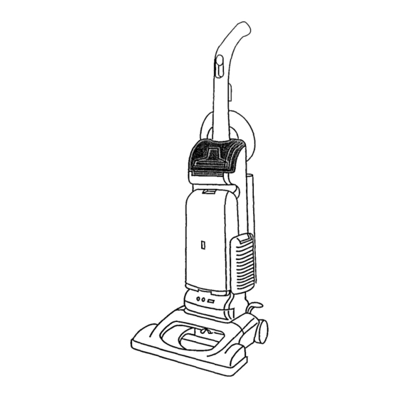
The WindTunnel
TM
series of uprights was first introduced
in mid 1997. Four deep wine colored
models comprised
the line and all were similar in overall appearance
like the
one in Figure
1.
Features
included
on the various
models:
• 13" and 15" nozzles
• Embedded
dirt finder (two models)
• Cords 31' and 35'
• Bag check indicator
(three models)
• Agitator,
replaceable
roll sleeve type
• Headlight,
one 12 volt 27313101
• Flat belt 38528033
• Hard bag enclosure
• One speed motor
• Stair cleaning
handle
• Four position height adjustment
• Tool storage on the cleaner
Micro-filtration
throw away bags Type "Y"
• Bag check indicator
(three models)
• 4, 5 or 6 stage filtration
• Edge cleaning "Edgers"
• Rotating
top cord hook
• 10' and 12' hose reach
Fig,
1
These cleaners operate on a clean air principle,
i.e., where
the dirty air enters the bag or dirt receptacle
before it goes
past the motor area. Since the same air is used to cool the
motor, it is extremely
important
that it be filtered ade-
quately to prevent dirt and dust from getting into the motor
and/or back into the room.
Basic operation
of the clean air system in these units is
illustrated
in Figure 2 on page 2.
Air fl0w
in the WindTunnel
is shown
in Figure
2A on
page 2.
7/97
Advertisement
Table of Contents
Troubleshooting

Related Manuals for Hoover WindTunnel U5465-900


Summary of Contents for Hoover WindTunnel U5465-900
- Page 1 WINDTUNNEL UPRIGHT The WindTunnel series of uprights was first introduced in mid 1997. Four deep wine colored models comprised the line and all were similar in overall appearance like the one in Figure Features included on the various models: • 13" and 15" nozzles •...
- Page 2 Dirty Air ffff_ Filtered Clean Air Filters Primary Filter T.A. Bag Secondary Motor Air flow shown using hose and tool. Fig. 2 Fig. 2A 7/97...
- Page 3 TYPE "Y" MICRO-FILTRATION throw away bags are Speci- fied on all models as the primary (2 stage) filter Figure Secondary filters are located behind a grill in the bottom of the Fig. 3 bag cavity Figure They can be washed and reinstalled when completely dry or replaced...
- Page 4 Key components of a deluxe WindTunnel model are shown in Figure Refer to the Hoover Service Manual for repair procedures and the Microfiche Parts Catalog light brown header for spare parts. On/Off Control Cord Hook Tool o_off Final Filter Check Bag...
- Page 5 Service Instructions WindTunnel Uprights Secvice Su_,'t 7/97...
- Page 6 WindTunnel wlo EDF TOOLDOOR HOLDER HOSE _ EXT. RILL BAGDOORGASKET ANGLED HOSE CONNECTOR ASSEMBLY BAG HOUSING BAGDOOR MOTOR MOTOR COVER MOUNT...
- Page 7 WindTunne| wlEDF =RINTED CIRCL ) ASSEMBLY COMPONENT NAMES ARE THE SAME AS PAGE 149 A-2 EXCEPT THOSE LISTED...
- Page 8 WindTunnel - 13" & 15" Width (Half Hood) TRUNNION BODY ADJ.LEVER FRONTWHEEL SUPPORT _ , t_" DUCTCOVERJ PICKER...
- Page 9 WindTunnel - 13" & 15" Width (Full Hood) HOOD-- TRUNNION COVER_ LEVER BODY FRONT WHEELI SUPPORT DUCTCOVER BOTTOMPLATE LITTER PICKER...
- Page 10 I. General III. Disassembly The WindTunnel cleaners are upright vacuums A. Bottom Plate - Agitator - Belt that feature computer designed air vanes to provide a powerful dual air stream which 1. Remove 4 screws and lift off bottom plate dramatically improves dirt pickup capabilities.
- Page 11 B. Duct Cover Pull short leg of spring backward and hook into track on wheel support. Slide out of main body (Held into place by bottom plate screws). (Fig. 3). Wheels and wheel shaft can be replaced by removing plastic wheel retainers. Note: Once Fig.
- Page 12 Note the position of cam for proper reassembly Improper assembly will cause the lever to lock into position. F. Main Body 1. Remove two R.H. and two L.H. trunnion screws - marked "A" (Fig. 9) Fig. 10 I. Hose Hose is replaced as an assembly.
- Page 13 M. Filter Holder K. Angled Hose Conn. Assembly. Deluxe, Plus and Supreme models: 1. Remove two screws which secures holder to 1. Remove screw (Fig. 12). bag housing and lift off. Standard Models: 1. Trapped into position by motor cover. N.
- Page 14 2. Lift wand / hose holder out of position. Dirt P. Headlight Lens Duct is trapped into position by wand / hose holder. On EDF models it is supplied with the 1. Remove two screws and lift off lens (Fig. 17). microphone.
- Page 15 T. Cord R, Wire Opening Plug 1. Remove strain relief. This plug is in the bottom of the EDF cavity. It is important to keep this plug in position to eliminate 2. Disconnect leads and replace cord. air leakage (Fig. 18) U.
- Page 16 III. Troubleshooting check list - WindTunnel The following is a guide to aid in determining the origin of a problem for which this model could conceivably be brought in for service Problem Possible Cause Possible Solution A. Motor won't Open in attachment cord. Replace cord.
- Page 17 Possible Solution Problem Possible Cause Note: When the unit is energized there is a slight delay then the green light illuminates If the green D EDF circuitry light does not come on check the following: not working Green light Check 120 volt leads on the LH side of the won't come No power to board board.
- Page 18 Troubleshooting Guide WindTunnel Cleaners...
- Page 19 The following is a guide to aid in determining the origin of a problem for which this model could conceivably be brought in for service. Possible Solution Problem Possible Cause Replece cord. A. Motor won't Open in attachment cord. Check connections at motor and insulated Open in wiring.
- Page 20 Possible Solution Problem Possible Cause Note When the unit is energized there is a slight delay then the green light illuminates If the green D EDF circuitry light does not come on check the following: not working Green light Check 120 volt leads on the LH side of the won't come No power to board board Also check connection at wire nut...
Need help?
Do you have a question about the WindTunnel U5465-900 and is the answer not in the manual?
Questions and answers