Patton electronics 2616RC User Manual
T1/e1 tdm-digital access concentrator (t-dac)
Hide thumbs
Also See for 2616RC:
- Specifications (2 pages) ,
- Getting started manual (80 pages) ,
- Administrator's reference manual (315 pages)
Table of Contents
Advertisement
Quick Links
See Chapter 2 for installa-
tion procedures & Chapter 3
for configuration procedures
Model 2616RC
T1/E1 TDM-Digital Access
Concentrator (T-DAC)
User Manual
Important
This is a Class A device and is intended for use in a light industrial environment. It is not intended nor approved for use in an industrial
or residential environment.
Sales Office:
+1 (301) 975-1000
Technical Support:
+1 (301) 975-1007
E-mail:
support@patton.com
WWW:
www.patton.com
Part Number: 07MD2616RC-GSG, Rev. E
Revised: February 16, 2012
Advertisement
Table of Contents

Related Manuals for Patton electronics 2616RC


Summary of Contents for Patton electronics 2616RC
-
Page 1: User Manual
See Chapter 2 for installa- tion procedures & Chapter 3 for configuration procedures Model 2616RC T1/E1 TDM-Digital Access Concentrator (T-DAC) User Manual Important This is a Class A device and is intended for use in a light industrial environment. It is not intended nor approved for use in an industrial or residential environment. - Page 2 Patton Electronics Company, Inc. 7622 Rickenbacker Drive Gaithersburg, MD 20879 USA Tel: +1 (301) 975-1000 Fax: +1 (301) 869-9293 Support: +1 (301) 975-1007 Web: www.patton.com E-Mail: support@patton.com Copyright © 2012, Patton Electronics Company. All rights reserved. The information in this document is subject to change without notice. Patton Elec- tronics assumes no liability for errors that may appear in this document.
- Page 3 Summary Table of Contents Introduction ..............................13 Hardware installation............................ 19 Configuring the T-DAC for operation ......................31 Operation and shutdown..........................58 Troubleshooting and maintenance ........................ 60 Contacting Patton for assistance ........................72 Compliance information ..........................75 68-pin SCSI-to-open-end 6-foot cable (part #10-3096TM68-6) ..............
-
Page 4: Table Of Contents
Contents About this guide..............................10 Audience................................10 Structure................................10 Precautions ................................11 Typographical conventions used in this document....................12 General conventions ............................12 Mouse conventions ............................12 Introduction ..............................13 Model 2616RC T1/E1 T-DAC overview ......................14 Hardware overview ..............................15 ................................15 ................................15 RS-232 control port ............................16 Power system ..............................16... - Page 5 Model 2616RC T-DAC User Manual Contents Introduction ................................32 Configuration prerequisites ...........................32 Initial configuration through the RS-232 control port...................33 Connecting the DB9-RJ45 adapter with the included cable ................33 Setting up the HyperTerminal (or similar program) session ................34 Using a browser to complete Model 2616RC configuration ..................37 Displaying the T-DAC 2616RC web administration pages ................38...
- Page 6 Model 2616RC T-DAC User Manual Contents Warranty Service and Returned Merchandise Authorizations (RMAs)..............73 Warranty coverage ............................73 Out-of-warranty service ..........................73 Returns for credit ............................73 Return for credit policy ..........................74 RMA numbers ..............................74 Shipping instructions ..........................74 Compliance information ..........................75 Compliance ................................76 ................................76 Safety ................................76...
- Page 7 List of Figures Model 2616RC T-DAC ..............14 Model 2616RC T-DAC features .
- Page 8 Model 2960 RAS Getting Started Guide T1 ALARMS PRESENT indicator on T1/E1 LINK ACTIVITY page ....... 51 Alarm Card Information window .
- Page 9 List of Tables General conventions ..............12 Mouse conventions .
-
Page 10: About This Guide
About this guide This guide describes installing and configuring a Patton Electronics Model 2616RC TDM-Digital Access Concentrator (T-DAC). By the time you are finished with this guide, your T-DAC will be connected to T1/ E1 lines and transferring data. The instructions in this guide are based on the following assumptions: •... -
Page 11: Precautions
Model 2616RC T-DAC User Manual About this guide Precautions Notes and cautions, which have the following meanings, are used throughout this guide to help you become aware of potential T-DAC problems. Warnings relate to personal injury issues, and Cautions refer to potential property damage. -
Page 12: Typographical Conventions Used In This Document
Model 2616RC T-DAC User Manual About this guide Typographical conventions used in this document This section describes the typographical conventions and terms used in this guide. General conventions The procedures described in this manual use the following text conventions: Table 1. General conventions Convention Meaning Indicates a cross-reference hyperlink that points to a figure, graphic,... -
Page 13: Introduction
Chapter 1 Introduction Chapter contents Model 2616RC T1/E1 T-DAC overview ......................14 Hardware overview ..............................15 ................................15 ................................15 RS-232 control port ............................16 Power system ..............................16 Central processing unit ...........................16 System timing ..............................16 Temperature ..............................16 Altitude ................................16 Humidity ................................16 Physical dimensions ............................16 Management services ............................16 LED display ..............................18... -
Page 14: Model 2616Rc T1/E1 T-Dac Overview
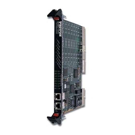
Model 2616RC T-DAC User Manual 1 • Introduction Model 2616RC T1/E1 T-DAC overview The Model 2616RC (see figure 1) provides 16 T1/E1 ports. A built-in digital cross-connect switch provides completely flexible grooming: the capability to connect any DS0-channel to any other DS0-channel from the WAN uplink ports or the T1/E1 ports. -
Page 15: Hardware Overview
Model 2616RC T-DAC User Manual 1 • Introduction Hardware overview The Model 2616RC combines transmission and networking technology concentrating 16 T1/E1 WAN links into a single slot blade for a Patton ForeFront chassis. The T-DAC front blade (see figure 2) contains a full set of LED status indicators presented on the front panel, and an RS-232 async control port. -
Page 16: Rs-232 Control Port
Model 2616RC T-DAC User Manual 1 • Introduction • 10Base-T half-/full-duplex operation (10 + 10) • Auto detection and fallback • 10/100 Mbps link and status indicators RS-232 control port The RS-232 port provides for initial configuration of the Model 2616RC. The RS-232 port supports: •... -
Page 17: Model 2616Rc Front Panel Leds
Model 2616RC T-DAC User Manual 1 • Introduction • SNMP version 1 configuration management • MIB II • TELNET via Ethernet • SYSLOG Client • Remote Software Upgrade via FTP • Built-in HTTP server for complete configuration and control using a standard web browser •... -
Page 18: Led Display
Model 2616RC T-DAC User Manual 1 • Introduction LED display Front panel LEDs (figure 3 on page 17) display the status of the WAN ports, the T1/E1 ports, the Ethernet LAN port, power, and the alarms. The LEDs are described in table Table 3. -
Page 19: Hardware Installation
Chapter 2 Hardware installation Chapter contents Introduction ................................20 Unpacking the Model 2616RC T-DAC ........................20 T-DAC blades installation.............................20 Cable installation..............................22 Connecting the Ethernet ports ........................22 Connecting the 10/100Base-T Ethernet port to an Ethernet switch or hub ..........22 Connecting the 10/100Base-T Ethernet port to an Ethernet-capable workstation or PC ........23 Connecting the EIA-561 RS-232 configuration port (DCE configured) ............23... -
Page 20: Introduction
Model 2616RC T-DAC User Manual 2 • Hardware installation Introduction This chapter contains the following procedures for installing the Model 2616RC T-DAC: Note Before installing the T-DAC, you will need to obtain the line type and encoding of the T1/E1 line from your local telephone company (Telco). •... -
Page 21: Alignment/Esd Pin And Card Handle
Model 2616RC T-DAC User Manual 2 • Hardware installation Note The T-DAC should be installed as close as possible to the termination jack provided by the Telco. The location should be well ventilated. Do not block the rack chassis’ cooling vents. 2. -
Page 22: Cable Installation
Model 2616RC T-DAC User Manual 2 • Hardware installation Cable installation This section describes installing the network interface cables. Connecting the Ethernet ports The T-DAC has a single 10/100 Ethernet interface for connection to your LAN (figure 5). The Ethernet port will autosense the correct speed of the local LAN and automatically negotiate half or full-duplex operation. -
Page 23: Connecting The 10/100Base-T Ethernet Port To An Ethernet-Capable Workstation Or Pc
Model 2616RC T-DAC User Manual 2 • Hardware installation Figure 6. Ethernet RJ-45 pin and signal definitions for T-DAC Connecting the 10/100Base-T Ethernet port to an Ethernet-capable workstation or PC The 10/100Base-T Ethernet port can connect to a single Ethernet-capable workstation or PC by means of a cross over cable. -
Page 24: Connecting The T1/E1 Wan Ports
Model 2616RC T-DAC User Manual 2 • Hardware installation Connecting the T1/E1 WAN ports An active T1/E1 is not necessary to configure the T-DAC. However, active T1/E1 connections are required when mapping WAN time slots to other WAN time slots. The factory-set default configuration of the Model 2616RC has the T1/E1 ports disabled. -
Page 25: Wan Cable's 68-Pin Scsi Connector
Model 2616RC T-DAC User Manual 2 • Hardware installation Figure 10. WAN cable‘s 68-pin SCSI connector 1. Connect the 68-pin SCSI connector (see figure 10) of the 6-foot WAN cable (see figure 9 on page 24) to the connector on the rear panel of the Model 2616RC. 2. -
Page 26: 68-Pin Scsi To Open End Cable
Model 2616RC T-DAC User Manual 2 • Hardware installation 68-pin SCSI to open end cable The SCSI-to-open-end cable (see figure 12) connects the 2616RC T1/E1 lines to a punch-down block via 24 gauge solid wire (0.5mm). The other end will be unterminated, open-end twisted pairs. Refer to table 5 punch-down block wiring information. -
Page 27: Wan Cable's 68 Non-Terminated Twisted-Pairs
Model 2616RC T-DAC User Manual 2 • Hardware installation Note The 64 wires in this cable are grouped into blue and orange binders of 32 wires each. Wires in the blue binder have the same color scheme as wires in the orange binder, so it is important to keep each binder sepa- rated to avoid confusion when connecting to a punch-down block. -
Page 28: Installing The Wan Cable To A Punch-Down Block
Model 2616RC T-DAC User Manual 2 • Hardware installation Table 5. WAN cable’s 68 non-terminated twisted-pairs (Continued) Port/Directio 68 Pin Wire Color Port/Directio 68 Pin Wire Color Pairs Pairs Positions Code Positions Code — NOT USED — NOT USED Installing the WAN cable to a punch-down block Materials required: •... -
Page 29: 68-Pin Scsi To Open End, 6 Foot Cable (Part #10-3096Tm68-6)-Obsolete
Model 2616RC T-DAC User Manual 2 • Hardware installation 3. Review SCSI pin-out (see table 5 on page 27) and punch-block pin-out and cut wires to the required length to reach their respective ports on the punch-down block. 4. Use punch-down tool to press wires down into block terminals. 5. -
Page 30: Completing The Hardware Installation
Model 2616RC T-DAC User Manual 2 • Hardware installation Completing the hardware installation This section verifies that the T-DAC hardware is operational to the point where you can begin configuring the software settings. Power is delivered from the Patton ForeFront chassis backplane through the 47-pin PICMG 2.11 power con- nectors on the 2616RC blades. -
Page 31: Configuring The T-Dac For Operation
Chapter 3 Configuring the T-DAC for operation Chapter contents Introduction ................................32 Configuration prerequisites ...........................32 Initial configuration through the RS-232 control port...................33 Connecting the DB9-RJ45 adapter with the included cable ................33 Setting up the HyperTerminal (or similar program) session ................34 Using a browser to complete Model 2616RC configuration ..................37 Displaying the T-DAC 2616RC web administration pages ................38... -
Page 32: Introduction
Model 2616RC T-DAC User Manual 3 • Configuring the T-DAC for operation Introduction This chapter contains the following procedures that describe configuring the Model 2616RC T-DAC for operation: • “Configuration prerequisites”—lists the items you need to have on hand before configuring the T-DAC. •... -
Page 33: Initial Configuration Through The Rs-232 Control Port
Model 2616RC T-DAC User Manual 3 • Configuring the T-DAC for operation Line Type: either E1 or E1-CRC Line Coding: either HDB3 or AMI Initial configuration through the RS-232 control port Initially you must configure the 2616RC’s IP address and—in rare instances—change the netmask from the default settings. -
Page 34: Setting Up The Hyperterminal (Or Similar Program) Session
Model 2616RC T-DAC User Manual 3 • Configuring the T-DAC for operation Setting up the HyperTerminal (or similar program) session Do the following: 1. At your PC, find the file HYPERTRM.EXE. Open a HyperTerminal session by double-clicking on the file name. -
Page 35: Com1 Properties Window
Model 2616RC T-DAC User Manual 3 • Configuring the T-DAC for operation 6. Configure your COM port settings as shown in figure 19, then click Figure 19. COM1 Properties window 7. Click on the menu, then select Properties. File 8. Configure the settings for Function, arrow and ctrl keys act as to Terminal keys as shown in figure 20, then click... -
Page 36: Login Window
Model 2616RC T-DAC User Manual 3 • Configuring the T-DAC for operation 9. Connect the male end of the 2616RC T-DAC’s power cables to the power outlets. 10. Boot up information will display on your HyperTerminal connection window, eventually followed by a login request window (see figure 21). -
Page 37: Using A Browser To Complete Model 2616Rc Configuration
Model 2616RC T-DAC User Manual 3 • Configuring the T-DAC for operation 13. Type for Ethernet, then press . The Ethernet configuration window displays (see figure 22). <Enter> Figure 23. Ethernet configuration window PrimaryIpAddress 14. Enter a for , then press <Enter>... -
Page 38: Displaying The T-Dac 2616Rc Web Administration Pages
Model 2616RC T-DAC User Manual 3 • Configuring the T-DAC for operation • Setting the system clocking parameters (see “Configuring the system clocking parameters” on page 41) • Configuring the IP default gateway (see “Configuring the default gateway” on page 40) Displaying the T-DAC 2616RC web administration pages Do the following: 1. -
Page 39: Home Page Window Panes
Model 2616RC T-DAC User Manual 3 • Configuring the T-DAC for operation Figure 25. HOME page window panes Figure 26. Operator Actions buttons From the Home page, the following actions can be performed: • Record Current Configuration—clicking on this button (see figure 26) saves the current configuration from volatile DRAM memory to FLASH memory. -
Page 40: Configuring The Default Gateway
Model 2616RC T-DAC User Manual 3 • Configuring the T-DAC for operation • Hard Reset—this button (see figure 26) causes the Model 2616RC to perform a cold restart. When you select Hard Reset, the T-DAC confirms that you want to execute this command. Then, the T-DAC will disconnect all current sessions, re-initialize the interfaces, and re-load configuration parameters from FLASH. -
Page 41: Configuring The System Clocking Parameters
Model 2616RC T-DAC User Manual 3 • Configuring the T-DAC for operation 5. In the Gateway box, type your default gateway IP address for the 2616RC. 6. Click the Add Route button to save your configuration. Figure 28. IP Routing Information window 7. -
Page 42: System Clocking Configuration Page, Example 1
Model 2616RC T-DAC User Manual 3 • Configuring the T-DAC for operation 3. Click the System Clocking hyperlink on the 2616RC Configuration Menu to open the System Clocking Configuration page (see figure 29). Figure 29. System Clocking Configuration page, example 1 4. -
Page 43: System Clocking Configuration Page, Example 2
Model 2616RC T-DAC User Manual 3 • Configuring the T-DAC for operation 2. Click the System Clocking hyperlink on the 2616RC Configuration Menu to open the System Clocking Configuration page (see figure 30). Figure 30. System Clocking Configuration page, example 2 3. -
Page 44: Configuring The Ds0 Mapping
Model 2616RC T-DAC User Manual 3 • Configuring the T-DAC for operation Configuring the DS0 mapping You need to make internal connections between a T1/E1 link and its destination. The destination of the T1/E1 link may be another T1/E1 port within the T-DAC, or the TDM bus in the chassis connecting to another T-DAC, DSL, or STM-1 card. - Page 45 Model 2616RC T-DAC User Manual 3 • Configuring the T-DAC for operation To define each DS0 Mapping you will create a static connection. “A” and “B” designate the two ends of the static connection. For each static connection you will define the following parameters: –...
-
Page 46: Configuring Line Settings And Signaling For E1
Model 2616RC T-DAC User Manual 3 • Configuring the T-DAC for operation 5. Under Dev Num B , select port1(1) Dev Slots B 1 - 32 6. Under , enter Dev Type B fromH110 7. Under , select 8. Under Dev Num B , select port1(1) -
Page 47: Configuring The E1 Line Interface Settings
Model 2616RC T-DAC User Manual 3 • Configuring the T-DAC for operation 2. View Link 1 corresponds to the first WAN circuit on the T-DAC. To the right of View Links 1-4 click the View Links... hyperlink to open the T1/E1 LINK ACTIVITY PORTS 1 – 4 page (see figure 36). -
Page 48: Line Type Pull-Down Menu
Model 2616RC T-DAC User Manual 3 • Configuring the T-DAC for operation Figure 38. Line Type pull-down menu 2. From the Line Coding pull-down menu (figure 39) select dsx1AMI(5) or dsxHDB3(3). Most installations will use HDB3. Figure 39. Line Coding pull-down menu with dsx1HDB3(3) selected 3. -
Page 49: Configuring Line Settings And Signaling For T1
Model 2616RC T-DAC User Manual 3 • Configuring the T-DAC for operation Figure 41. E1 ALARMS PRESENT indicator After you connect the E1 line to the WAN port on the rear of the Model 2616RC these alarms should disappear. Configuring line settings and signaling for T1 Accessing the Line Interface Settings 1. -
Page 50: Configuring The T1 Line Settings
Model 2616RC T-DAC User Manual 3 • Configuring the T-DAC for operation 3. Click the Configuration… hyperlink, then click the Modify Configuration... hyperlink to open the WAN Circuit CONFIGURATION LINK window (figure 44) and view the Line Interface Settings. Figure 44. WAN Circuit Configuration page, Line Interface Settings Configuring the T1 line settings 1. -
Page 51: Line Coding Pull-Down Menu With Dsx1B8Zs(2) Selected
Model 2616RC T-DAC User Manual 3 • Configuring the T-DAC for operation 2. From the Line Coding pull-down menu (figure 46), select dsx1B8ZS(2) or dsx1AMI(5). Figure 46. Line Coding pull-down menu with dsx1B8ZS(2) selected 3. From the Line Build Out pull-down menu (figure 47) select t1pulse0dB(1). -
Page 52: Enabling/Disabling The Alarm Card
Model 2616RC T-DAC User Manual 3 • Configuring the T-DAC for operation Enabling/disabling the alarm card The Alarm Card window (see figure 49) is where you can configure the alarm card polling mode to determine whether the 2616RC monitors the alarm card status for the chassis. 1. -
Page 53: Saving Your Configuration
Model 2616RC T-DAC User Manual 3 • Configuring the T-DAC for operation Saving your configuration At this point you have completed the basic configuration of your T-DAC for operation. To save your configu- ration settings in non-volatile RAM, do the following: 1. -
Page 54: Import/Export Page
Model 2616RC T-DAC User Manual 3 • Configuring the T-DAC for operation To import or export a configuration, do the following: 1. On the Configuration Menu pane, click the Import/Export hyperlink to display the IMPORT/EXPORT page (see figure 51). Figure 51. IMPORT/EXPORT page Backing up your configuration parameters... -
Page 55: Backing Up The Configuration Store In Flash Memory
Model 2616RC T-DAC User Manual 3 • Configuring the T-DAC for operation Backing up the configuration store in flash memory 1. To make a back-up copy of the configuration file currently stored in your T-DAC’s flash memory: – On the Import/Export page (figure 52) click the Export Flash... -
Page 56: Completing The Installation
Model 2616RC T-DAC User Manual 3 • Configuring the T-DAC for operation – To save the displayed data as a text file, use your browser’s Save function (figure 53). Using Netscape or Internet Explorer, for example. • Click the File menu. •... - Page 57 Model 2616RC T-DAC User Manual 3 • Configuring the T-DAC for operation Note If the T-DAC does not behave as described, the most likely cause is that the T-DAC default settings are not compatible with the T1/E1 line. If this is the case, use the RS-232 CONFIG port to correct the T-DAC settings.
-
Page 58: Operation And Shutdown
Chapter 4 Operation and shutdown Chapter contents Introduction ................................59 Activating the Model 2616RC..........................59 De-activating the Model 2616RC .........................59... -
Page 59: Introduction
Model 2616RC T-DAC User Manual 4 • Operation and shutdown Introduction This chapter describes how to start up and power down the Model 2616RC. Activating the Model 2616RC The Model 2616RC is activated by completing the procedures in Chapter 2, “Hardware installation” and Chapter 3, “Configuring the T-DAC for operation”. -
Page 60: Troubleshooting And Maintenance
Chapter 5 Troubleshooting and maintenance Chapter contents Introduction ................................61 Fault analysis .................................62 T1/E1 port test modes............................64 DSX1 payload loop (dsx1PayloadLoop) ......................64 DSX1 line loop (dsxLineLoop) ........................65 Periodic maintenance ............................66 Calibration ..............................66 Maintenance................................66 Exporting the current Model 2616RC configuration ..................66 Removing the defective Model 2616RC ....................69 Installing the replacement Model 2616RC ....................70... -
Page 61: Symptoms
Model 2616RC T-DAC User Manual 5 • Troubleshooting and maintenance Introduction This chapter describes troubleshooting and fault analysis that can be performed by the operator. If you require more help, refer to Chapter 6, “Contacting Patton for assistance”. Refer to table 6 for a list of common symp- toms and suggested remedies. -
Page 62: Fault Analysis
Model 2616RC T-DAC User Manual 5 • Troubleshooting and maintenance Fault analysis The following procedures outline steps you should follow when troubleshooting a Model 2616RC malfunction. 1. If possible, talk to the person who filed the trouble complaint and determine the operational symptoms. Record the symptoms on the appropriate trouble report form (include the front panel LED indications). - Page 63 Model 2616RC T-DAC User Manual 5 • Troubleshooting and maintenance Table 7. LED definitions (Continued) Location Color Status Meaning SYSTEM Front Green Flash- The Model 2616RC is operating normally. No action rec- panel ommended. The Model 2616RC is not functioning properly. As soon as possible, unplug both power cables from the Model 2616RC, wait 30 seconds, then plug the cables back into the Mode 2616RC to see if the problem disappears.
-
Page 64: T1/E1 Port Test Modes
Model 2616RC T-DAC User Manual 5 • Troubleshooting and maintenance Table 7. LED definitions (Continued) Location Color Status Meaning READY Front panel Blue Card ready for removal from Patton ForeFront chassis. Card not ready for removal from Patton ForeFront chassis. Do not remove card from chassis. -
Page 65: Dsx1 Line Loop (Dsxlineloop)
Model 2616RC T-DAC User Manual 5 • Troubleshooting and maintenance DSX1 line loop (dsxLineLoop) When activated, data received at the selected T1/E1 port, is looped back to the originating device (see figure 55). Data is looped at the T1/E1 port. Figure 55. -
Page 66: Periodic Maintenance
Model 2616RC T-DAC User Manual 5 • Troubleshooting and maintenance Periodic maintenance Consult the rack chassis user manual for information on preventative maintenance (such as cleaning the chassis air cooling vents to remove accumulated dust). Calibration The Model 2616RC requires no calibration. Maintenance If you isolate a problem to the a Model 2616RC component, the entire Model 2616RC must be replaced as follows. -
Page 67: Import/Export Page
Model 2616RC T-DAC User Manual 5 • Troubleshooting and maintenance Figure 56. IMPORT/EXPORT page Maintenance... -
Page 68: Example T-Dac Flash Memory Configuration File Displayed In A Browser
Model 2616RC T-DAC User Manual 5 • Troubleshooting and maintenance 3. To make a back-up copy of the configuration file currently stored in your T-DAC’s flash memory: – On the Import/Export page (figure 56 on page 67) click the Export Flash... hyperlink. The T-DAC will get the configuration file currently stored in your T-DAC’s flash memory and display it in your browser (figure Figure 57. -
Page 69: Removing The Defective Model 2616Rc
Model 2616RC T-DAC User Manual 5 • Troubleshooting and maintenance – To save the displayed data as a text file, use your browser’s Save function (see figure 58). Using Netscape or Internet Explorer, for example. • Click the File menu. •... -
Page 70: Installing The Replacement Model 2616Rc
Model 2616RC T-DAC User Manual 5 • Troubleshooting and maintenance 3. Unlock the handles by pressing the red button on each handle. The button immediately activates the switch (turning it to an open position), while the button itself remains depressed. The blade can then be removed. -
Page 71: Completing The Installation
Model 2616RC T-DAC User Manual 5 • Troubleshooting and maintenance Completing the installation This section verifies that the Model 2616RC is fully operational. 1. Verify that the green POWER LED is lit. If the POWER LED is flashing green, refer to Chapter 5, “Trou- bleshooting and maintenance”... -
Page 72: Contacting Patton For Assistance
Chapter 6 Contacting Patton for assistance Chapter contents Introduction ................................73 Contact information..............................73 Warranty Service and Returned Merchandise Authorizations (RMAs)..............73 Warranty coverage ............................73 Out-of-warranty service ..........................73 Returns for credit ............................73 Return for credit policy ..........................74 RMA numbers ..............................74 Shipping instructions ..........................74... -
Page 73: Introduction
Model 2616RC T-DAC User Manual 6 • Contacting Patton for assistance Introduction This chapter contains the following information: • “Contact information”—describes how to contact PATTON technical support for assistance. • “Warranty Service and Returned Merchandise Authorizations (RMAs)”—contains information about the RAS warranty and obtaining a return merchandise authorization (RMA). -
Page 74: Return For Credit Policy
Model 2616RC T-DAC User Manual 6 • Contacting Patton for assistance Return for credit policy • Less than 30 days: No Charge. Your credit will be issued upon receipt and inspection of the equipment. • 30 to 120 days: We will add a 20% restocking charge (crediting your account with 80% of the purchase price). -
Page 75: A Compliance Information
Appendix A Compliance information Chapter contents Compliance ................................76 ................................76 Safety ................................76 PSTN Regulatory ............................76 Radio and TV Interference ............................76 Industry Canada Notice ............................76 FCC Part 68 (ACTA) Statement ...........................77 CE Declaration of Conformity ..........................77 Authorized European Representative ........................77... -
Page 76: Compliance
Model 2616RC T-DAC User Manual A • Compliance information Compliance • FCC Part 15, Class A • EN55022, Class A • EN55024 Safety • UL60950-1/CSA C22.2 No. 60950-1 • IEC/EN 60950-1 • AS/NZS 60950-1 PSTN Regulatory • FCC Part 68 •... -
Page 77: Fcc Part 68 (Acta) Statement
Model 2616RC T-DAC User Manual A • Compliance information designated by the supplier. Any repairs or alterations made by the user to this equipment, or equipment mal- functions, may give the telecommunications company cause to request the user to disconnect the equipment. Users should ensure for their own protection that the ground connections of the power utility, telephone lines and internal metallic water pipe system, are connected together. -
Page 78: 68-Pin Scsi-To-Open-End 6-Foot Cable (Part #10-3096Tm68-6)
Appendix B 68-pin SCSI-to-open-end 6-foot cable (part #10-3096TM68-6) Chapter contents Introduction ................................79... -
Page 79: Introduction
Model 2616RC T-DAC User Manual B • 68-pin SCSI-to-open-end 6-foot cable (part #10-3096TM68-6) Introduction The SCSI-to-open-end cable connects the 2616RC T1/E1 lines to a punch-down block via 24 gauge solid wire (0.5mm). Refer to table 8 for punch-down block wiring information. Table 8. - Page 80 Model 2616RC T-DAC User Manual B • 68-pin SCSI-to-open-end 6-foot cable (part #10-3096TM68-6) Introduction...