Table of Contents
Advertisement
Quick Links
'S
i
19.2 VOLT HAMMER DRILL
1/2 in. Variable Speed
MANUAL
1
Model No.
31 5.114840
WARNING:
To reduce the risk of injury,
the user must read and understand the
operator's manual before using this
product.
Customer
HeUp Line: 1-800-932-3188
Sears, Roebuck
and Co., 3333 Bevedy Rd., Hoffman
Estates, IL 60179 USA
Visit the Craftsman web page: www.sears.com!craftsman
983000-487
8-04
Save this manual
for future
reference
Advertisement
Table of Contents

Related Manuals for Craftsman 315.114840


Summary of Contents for Craftsman 315.114840
- Page 1 Customer HeUp Line: 1-800-932-3188 Sears, Roebuck and Co., 3333 Bevedy Rd., Hoffman Estates, IL 60179 USA Visit the Craftsman web page: www.sears.com!craftsman Save this manual for future reference 983000-487 8-04...
-
Page 2: One Year Full Warranty
NEAREST SEARS STORE OR SEARS PARTS & REPAIR CENTER (N THE UNITED STATES, and Sears w(U repa(r (t, free of charge. (f this Craftsman too( is used for commercial or rental purposes, th(s warranty applies for only 90 days from the date of purchase. -
Page 3: Personal Safety
[] Do not overreach. Keep proper footing and balance WARNING!READ ANDUNDERSTAND ALL iNSTRUCTiONS. Failure to followallinstructions st all times. Proper footing and balance enable better listedbelow, m ayresult i nelectricshock, f ireand/or control of the too! in unexpected situations. serious personal injury. [] Use safety equipment. - Page 4 SERVmCE [] When servicing a tool, use only identical replace- ment parts. Follow instructions in the Maintenance [] Tool service must be performed only by qualified section of this manual. Use of unauthorized parts or repair personnel. Service or maintenance performed failure to follow Maintenance hstructions may create a by unqualified personne! may result in a risk of injury.
- Page 5 a. That pins on plug of extension cord are the WARNING! READ AND UNDERSTAND ALL iNSTRUCTiONS° Failure to follow all instructions same number, size and shape as those of plug on charger. listed below, may result in electric shock, fire and/or serious personal injury.
- Page 6 Someof the followingsymbolsmaybe usedon this too!. Please studythemand learntheirmeaning. P roper interpretation o f thesesymbolswillallowyouto operate the too!betterandsafer. SYMBOL NAME DESIGNATION/EXPLANATmON Volts Voltage Amperes Current Hertz Frequency ( cyclespersecond) Watt Power Minutes Time Alternating Current Typeofcurrent Direct C urrent Typeor a characteristic o f current NoLoadSpeed Rotational speed,at no load ClassII Construction...
- Page 7 Thefollowing signal w ordsandmeanings a reintended to explain the levels of riskassociated withthisproduct. SYMBOL SIGNAL MEANING DANGER: hdicates an imminently hazardous situation, which, if not avoided, will result in death or serious injury. WARNING: hdicates a potentially hazardous situation, which, if not avoided, could result in death or serious injury.
-
Page 8: Product Specifications
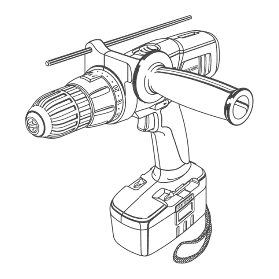
PRODUCT SPECIFICATIONS Chuck .................................... 1/2 in. Clutch ..................................24 Position Motor ................................... 19.2 Volt DC Switch ................................Variable Speed Gear Box ................................... 2 Speed No Load Speed ............................0-400/0-1400/min. Hammer Speed ........................... 0-5200/0-18200 BPM* Charger hput ............................120 V, 60 Hz, AC only Charge Rate ................................. - Page 9 KNOW YOUR HAMMER DR(LL DEPTH GAUGE See Figure 1. A depth gauge rod is installed on the auxiliary handle Before attempting to use this product, familiarize yourself assembly to assist you in controlling the depth of drilled holes, with a(I operat(ng Features and Safety Rules, KEYLESS CHUCK AUXIMARY...
- Page 10 UNPACKING WARNING: Hfany parts are missing do not operate this tool until the missing parts are replaced. Failure This product has been shipped completely assembled. to do so could result in possible serious personal [] Carefully remove the tool and any accessories from the injury.
- Page 11 CHARGmNG THE BATTERY PACK [] If both yellow and green LEDs come on, this indicates a deeply discharged or defective battery pack. Allow The battery pack for this tool has been shipped in a low the battery pack to remain in the charger for 15 to 30 charge condition to prevent possible problems.
- Page 12 SWITCH TO mNSTALL BATTERY PACK See Figure 3. See Figures 5 - 6. To turn your ddll ON, depress the switch trigger, To turn it [] Lock switch trigger on your drill by placing the direction OFF, release the switch trigger, of rotation selector in center position.
- Page 13 SWITCHLOCK WARN(NG: Do not hold chuck body with one hand and use power of the drift to tighten chuck jaws on Bee ,Figure 6. drift bit. Chuck body could slip in your hand or your The switch trigger can be locked in the OFF position, This hand could slip and come in contact with rotating drift feature can be used to prevent the possibility of accidental bit.
- Page 14 TO DEOREASE WARNING:Make sureto insert d rillbit straight i nto TORQUE TORQUE chuckjaws.Donotinsert d rillbit intochuckjaws ADJUSTINGRING at ananglethentighten, a sshownin Figure 8.This couldcause drillbit to bethrown fromddll,resulting inpossible serious personal injury or damage tothe chuck. Fig. 9 USmNG THE HAMMER MODE See Figure 10.
- Page 15 BiT STORAGE DRILLING See Figure 11. See Figure 13. LEVEL When not in use, bits provided with your drill can be placed in the storage area iocated on the bottom of your drill. SCREWDRIVER BiT BIT STORAGE AREA Fig. 11 WARNING: Always wear safety goggles or safety glasses with side shields when operating tools.
- Page 16 WARNING: T oprevent a cc(dental starting that ADJUST(NG THE DEPTH GAUGE ROD cou(d causeserious persona( (njury, a iways remove See Figure 15. the battery packfromthetoo(whenmaking adjust- Follow these steps to adjust the depth gauge rod, ments. Lock the tr(gger switch by p(acing the rotation selector (n the center position, AOJUST(NG THE AUXIL(ARY...
-
Page 17: Chuck Removal
CHUCK REMOVAL TO RETIGHTEN A LOOSE CHUCK See Figures 16 ° 18. The chuck may become loose on spindle and develop a The chuck may be removed in order to use some acces- wobble, Periodically check chuck screw for tightness, sories, To remove: [] Lock the switch trigger by placing the direction of rota-... -
Page 18: General Maintenance
WARNING:Whenservicing, useonlyidentical WARMNG: Do not at any time let brake fluids, Craftsman r eplacement parts.Useofanyotherpart gasoline, petroleum-based products, penetrating maycreatea hazard or cause productdamage. oils, etc. come in contact with plastic parts. Chemi- cals can damage, weaken or destroy plastic which may result in serious personal injury. - Page 19 CRAFTSMAN 19.2V CORDLESS HAMMER E)R_LL - 315.114840 SEE BACK PAGE FOR PARTS ORDERING _NSTRUCT_ONS Number Description Qty. 6613402 Chuck Screw ................... 300188024 Auxiliary Handle Assembly .............. 690033052 Chuck ....................630412003 Depth Gauge Rod ................940203007 Logo Plate ..................1323903 Battery Pack (Item no. _911375) ............
- Page 20 Your Home For repair-in your home-of all major brand appliances, lawn and garden equipment, or heating and cooling systems, no matter who made it, no matter who sold it! ....For the replacement parts, accessories owner's manuals that you need to do-it-yourself....
Need help?
Do you have a question about the 315.114840 and is the answer not in the manual?
Questions and answers