Table of Contents

Related Manuals for Craftsman C950-52119-3


Summary of Contents for Craftsman C950-52119-3
- Page 1 S _ARS SWA/RS CRAFTSMRN owner's manual DUAL STAGE Model SNOW BLOWER C950-52119-3 9-H.P. 27 inch CAUTION: You must read and understand this owner's manual before operating unit. Serial No. F-O31020L SEARS CANADA INC., TORONTO, ONTARIO M5B 2B8 Printed inU,S,A,...
-
Page 2: Rules For Safe Operation
RULES FOR SAFE OPERATION IMPORTANT spark plug to prevent accidental starting during: Preparation, Maintenance, or Storage of your ARNING: Always disconnect the spark plug wire and place it where it cannot make contact with snow blower. SAFE OPERATION PRACTICES FOR WALK-BEHIND SNOW BLOWER DO NOT OPERATE THIS EQUIPMENT BEFORE READING... - Page 3 RULES FOR SAFE OPERATION MAINTENANCE AND STORAGE Take all possible precautions when leaving the snow blower unattended. Disengage the auger/impeller, shift Check shear bolts and other bolts at frequent intervals for to neutral, stop engine, and remove key. proper tightness to be sure the equipment is in safe work- ing condition.
-
Page 4: Owner's Information
3. Tire replacement or repair caused by punctures from outside objects, such as nails, thorns, stumps or glass. 4. In home service. Warranty service is available by returning the Craftsman snow blower to the nearest Sears Service Centre/Department in Canada. This warranty applies only while this product is in use in Canada. -
Page 5: Table Of Contents
TABLE OF CONTENTS RULES FOR SAFE OPERATION ....SERVICE RECOMMENDATIONS ....OWNER'S INFORMATION ......CUSTOMER RESPONSIBILITIES ....SNOW BLOWER ......ASSEMBLY ........TOOLS REQUIRED FOR ASSEMBLY ..... AS REQUIRED ........ LUBRICATION AT STORAGE ....CONTENTS OF SHIPPING CARTON ....LUBRICATION - EVERY 10 HOURS ..... -
Page 6: Assembly
ASSEMBLY TOOLS REQUIRED FOR ASSEMBLY CONTENTS OF SHIPPING CARTON 1 - Knife 1- Snow Blower 2 - 1/2" wrenches (or adjustable wrenches) 1- Container of Fuel Stabilizer 2 - 9/16" wrenches (or adjustable wrenches) 1- Snow Chute Assembly 2 - 3/4" wrenches (or adjustable wrenches) 1- Crank Assembly 1 - 3/8"... -
Page 7: Unpacking
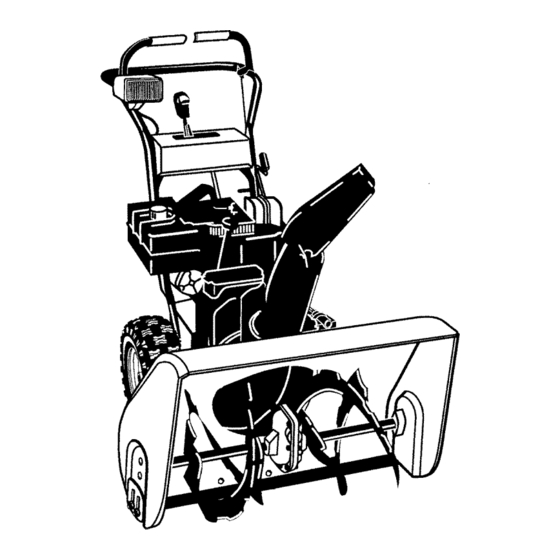
ASSEMBLY Figure 1 shows the snow blower in the shipping position. Figure 2 shows the snow blower completely assembled. Reference to right and left hand side of the snow blower is from the operator's position at the handle. UNPACKING Locate the two tear tabs at the bottom of the carton. Figure 1 Traction Drive Auger Drive... -
Page 8: Upper Handle And Crank Assembly
ASSEMBLY UPPER HANDLE AND CRANK ASSEMBLY Adap_rBo_ Loosen, but do not remove the screws, flatwashers, lock- _" Bolt washers and hex nuts in the upper holes of the lower han- Lockwasher dle. Locknut Nutt_ Remove the fasteners and the crank assembly eyebolt from the lower holes of the lower handle. -
Page 9: Speed Select Lever
ASSEMBLY SPEED SELECT LEVER Shifter Bracket Cut plastic tie securing speed select lever assembly to the shifter bracket. (See Figure 7) Plastic Tie Remove locknut, washer, spring, and the bolt. (See Figure 9) Position speed selector lever assembly as shown in Figure 8. -
Page 10: Snow Chute Assembly
ASSEMBLY SNOW CHUTE ASSEMBLY HEADLIGHT ASSEMBLY Position the snow chute onto the snow chute flange. Al- The headlight is mounted on the right side of the upper handle. It is installed upside_lown for shipping purposes. ign the three holes in the snow chute with holes in snow chute flange. -
Page 11: Engine And Snow Blower Overview
OPERATION Get to know your snow blower and its controls. Be sure you (or any other operator) have read and understood the Operation Precautions listed on page 2 of this manual. Traction Drive Auger Drive Clutch Lever Clutch Lever Traction Drive Oil Fill Cap/Dipstick Cable Electric Start Button... -
Page 12: Snow Blower Operation
OPERATION result in severe eye damage. Always wear safety glasses or eye shields before beginning snow blower The operation of any snow blower can result in foreign objects being thrown into the eyes,which can Operation. We recommend standard safety glasses or Wide Vision Safety Mask for over spectacles. SNOW BLOWER OPERATION WARNING: Read Owner's Manual before oper-... -
Page 13: Wheel Lock Out Pin
OPERATION To stop forward motion, release traction drive clutch lever (left hand - Figure 15). WARNING: Never run engine indoors or in an enclosed, poor ventilated area. Engine exhaust contains CARBON MONOXIDE, DERLESS and DEADLY GAS. To stop the auger, release auger drive clutch lever (right hand - Figure 15). -
Page 14: Before Starting Engine
OPERATION BEFORE STARTING ENGINE Check to make sure that spark plug is tightened securely into engine and spark plug wire is attached to spark plug. Check the oil If torque wrench is available, torque plug to 18-23 ft_bs. NOTE: The engine was shipped from the factory filled with oil. -
Page 15: To Start Engine
OPERATION With the engine running, push the starter button and spin As engine warms up move choke lever to "1/2 choke" the starter for several seconds. position. When engine does not run smoothly, move choke lever to the off position. NOTE: The normal sound made by spinning the starter will not harm the engine or the starter. - Page 16 OPERATION NOTE: Never cover snow blower while engine and exhaust area are still warm. Starter Button OF ELECTRIC STARTER On models so equipped WARNING: The electric starter is equipped with a three-wire power cord and plug designed to operate on 120 volt AC house hold current. The power cord must be properly grounded at all times to Power cord avoid the possibility of electric shock which can cause...
- Page 17 OPERATION Push STARTER BUTTON (Figure 21) to engage IN TEMPERATURES ABOVE 0°F (-18°C) starter motor and crank engine. Move throttle control to"FAST" position. IN TEMPERATURES BELOW 0°F (-18°C) Rotate CHOKE KNOB to the on position while crank- Move throttle control to "1/2 THROTTLE" position. Allow ing engine.
-
Page 18: Operating Tips
OPERATION OPERATING TIPS Before starting snow blower, always inspect augers and impeller for ice accumulation and/or debris, which could For optimum snow blower efficiency, adjust ground result in snow blower damage. speed, not the throttle. REMEMBER - if the wheels slip, forward speed will be reduced. -
Page 19: Service Recommendations
SERVICE RECOMMENDATIONS SERVICE RECOMMENDATIONS FIRST BEFORE EVERY EVERY EVERY BEGINNING EACH EACH BEFORE PROCEDURE HOUR OFTEN HOURS HOURS HOURS SEASON STORAGE Tighten all screws and nuts Check Traction Clutch Cable Ad ustment (See Cab e Ad ustment) Check Auger clutch Cable Ad ustment (See Cab e Ad ustment) Adjust Drive Belts... -
Page 20: Customer Responsibilities
CUSTOMER RESPONSIBILITIES Some adjustments will need to be made periodically to properly maintain your snow blower. All adjustments in ADJUSTMENTS/REPAIRS section of this manual should be checked at least once each season. SNOW BLOWER The following adjustment should be performed more than once each season. -
Page 21: Lubrication - Every 25 Hours
CUSTOMER RESPONSIBILITIES LUBRICATION - EVERY 25 HOURS Chute Rotation Gear Lubricate the chute rotation gear with automotive type oil. (see Figure 24). Chains Lubricate the chains with a chain type lubricant. Wipe the hexshaft and sprockets with 5W30 motor oil. Position speed selector lever in first (1) forward gear. -
Page 22: Engine
CUSTOMER RESPONSIBILITIES ENGINE Check Crankcase Oil Level before starting engine and after each 5 hours of continuous use (see Figure 26). Add proper motor oil as required. NOTE: Overfilling the engine can affect performance. Tighten the oil fill cap securely to prevent leakage. Change Oil every 25 hours of operation or at least once a year, even if the snow blower is not used for twenty-five hours. -
Page 23: Adjustment/Repair
ADJUSTMENT/REPAIR To adjust skids, proceed as follows: WARNING: Always turn unit off, remove igni- tion key and disconnect the spark plug wire be- Place a block (equal to height from ground desired) un- fore making any repairs or adjustments. der scraper bar near but not under skid. AUGER HOUSING HEIGHT ADJUSTMENT... -
Page 24: Belt Adjustment
ADJUSTMENT/REPAIR BELT ADJUSTMENT Traction Drive Belt The traction drive belt has constant spring pressure and does not require an adjustment. If the traction drive belt is slipping, replace the belt. See "How To Replace The Belts" in the Maintenance section. Auger Drive Belt If your snow blower will not discharge snow, check the control cable adjustment. -
Page 25: How To Remove The Auger Drive Belt
ADJUSTMENT/REPAIR HOW TO REPLACE THE BELTS Adjust the auger drive belt. See "How To Adjust The Au- ger Drive Belt" in the Maintenance section. 10. Adjust the belt guide. See "How To Adjust The Belt The drive belts are of special construction and must be Guide"... -
Page 26: Howto Remove The Traction Drive Belt
ADJUSTMENT/REPAIR How To Remove the Traction Drive Belt If the snow thrower will not move forward, check the traction 11. Install and adjust the auger drive belt. See "How To Re- drive belt for wear or damage. If the traction drive belt is worn move The Auger Drive Belt"... -
Page 27: Belt Guide Adjustment
ADJUSTMENT/REPAIR BELT GUIDE ADJUSTMENT Remove spark plug wire. Have someone engage auger drive. __O_ 1B_8tl _uld(_. 175 m m) Measure the distance between the belt guide and belt. Auger Idler The distance should be 1/8 inch (3.175 mm) for guide. See Figure 34. - Page 28 ADJUSTMENT/REPAIR Traction Drive Cable Adjustment Bolt Bottom Panel WARNING: Drain the gasoline outdoors, away from fire or flame. Remove the gas from the gas tank. Stand the snow Auger Housing thrower up on the front end of the auger housing. Loosen the bolts on each side of the bottom panel (see Figure 37).
-
Page 29: How To Adjust Or Replace The Friction Wheel
ADJUSTMENT/REPAIR HOW TO ADJUST OR REPLACE Install the bottom panel (see Figure 40). THE FRICTION WHEEL Tighten the bolts on each side of the bottom panel. How To Check The Friction Wheel If the snow thrower will not move forward, check the traction drive bell the traction drive cable or the friction wheel. -
Page 30: How To Replace Friction Wheel
ADJUSTMENT/REPAIR How To Replace The Friction Wheel If the friction wheel is worn or damaged, the snow thrower will not move forward. The friction wheel must be replaced as follows. Remove the gas from the gas tank. Stand the snow thrower up on the front end of the auger housing (4). - Page 31 ADJUSTMENT/REPAIR 10. Remove the three fasteners that hold the friction wheel to the hub (see Figure 46). 11. Remove the friction wheel from the hub. Slip the fric- tion wheel off the hex shaft. 12. Assemble the new friction wheel onto hub with the fas- teners removed earlier.
-
Page 32: Auger Shear Bolt Replacement
ADJUSTMENT/REPAIR AUGER SHEAR BOLT REPLACEMENT The augers are secured to the auger shaft with special bolts NOTE: For the operator's convience, the shear bolt that are designed to break if an object becomes lodged in the wrenches are located in the toolbox. auger housing. -
Page 33: Storage
STORAGE OFF SEASON STORAGE Lubricating the piston/cylinder area. This can be done by WARNING: Never store engine with fuel in tank first removing the spark plug and squirting clean engine indoors or in enclosed, poorly ventilated enclo- sures, where fuel fumes may reach an open oil into the spark plug hole. -
Page 34: Trouble Shooting Chart
TROUBLE SHOOTING CHART PROBLEM LOOK FOR REMEDY Difficult starting Defective spark plug. Replace defective spark plug. Engine runs erratically Blocked fuel line. Clean fuel line. Empty gas tank. Check fuel supply, Stale gasoline. Add fresh gasoline. Water or dirt in fuel system. Remove carburetor bowl to drain fuel tank. -
Page 35: Repairparts
REPAIRPARTS CRAFTSMAN 27" SNOW BLOWER C950-52119-3 PIECESDE RECHANGE CRAFTSMAN 27" CHASSE-NEIGE C950-52119-3 ENGINE/ MOTEUR 25-2 25-3 25-2 Ref. Drive Page Ref. Auger Housing Page Key No. N° sur le Part No. schema N° de pibce Description Description ENGINE MOTEUR 002x97 BOLT, CARRIAGE 5/16=18 BOULON, PO. - Page 36 CRAFTSMAN 27" SNOW BLOWER C950-52119-3 REPAIR PARTS PII=CES DERECHANGE CRAFTSMAN 27" CHASSE-NEIGE C950-52119-3 FRAME / BATI Ref. Engine Page "_ Ref. Auger Housing Page Ref. Drive Page F-031020L...
- Page 37 CRAFTSMAN 27" SNOW BLOWER C950-52119-3 REPAIR PARTS PII=CES DERECHANGE CRAFTSMAN 27" CHASSE-NEIGE C950-52119-3 FRAME / BATI Key No. Nosurie Part No. schema N° de piece Description Description 1501055E701 COVER, BOTTOM PANNEAU INFERIEUR 310169 SCREW, 1/4=20X .63 VIS 1/4-20X 1501226 YZ IDLER ASSEMBLY, AUGER BRAS DE POULIE LIBRE.
- Page 38 CRAFTSMAN 27" SNOWBLOWERC950-52119-3 REPAIRPARTS CRAFTSMAN 27" CHASSE-NEIGEC950-52119-3 PII=CES DE RECHANGE DRIVE / BATI DE MONTAGE DU MOTEUR 1--_ Ref. Shift Yoke Page Ref. Frame Page _Ref. Wheel Page ® 238 215 Ref. Wheel Page Wheel Page F-031020L...
- Page 39 CRAFTSMAN 27" SNOWBLOWERC950-52119-3 REPAIRPARTS CRAFTSMAN 27" CHASSE-NEIGEC950-52119-3 PII=CES DE RECHANGE DRIVE / BATI DE MONTAGE DU MOTEUR Key No. Nosurle Part No. schema N° de piece Description Description 1501092 LF AXLE, SWING PLATE YZ PANNEAU ARTICULE 579851 CHAIN, ROLLER #428 x19.80 CHAINE A GALETS #428 x19.80...
-
Page 40: Repair Parts
REPAIRPARTS CRAFTSMAN 27" SNOW BLOWER C950-52119-3 PIECESDE RECHANGE CRAFTSMAN 27" CHASSE-NEIGE C950-52119-3 AUGER HOUSING / VIS SANS FIN Ref. Gear Case Assy F-031020L... - Page 41 REPAIRPARTS CRAFTSMAN 27" SNOW BLOWER C950-52119-3 PII=CES DE RECHANGE CRAFTSMAN 27" CHASSE-NEIGE C950-52119-3 AUGER HOUSING / VIS SANS FIN Key No. NOsur le Part No. schema N° de piece Description Description 583146 PULLEY, 4L 8.40 OD. POULIE 4L 8.40 2001022...
- Page 42 CRAFTSMAN 27" SNOW BLOWER C950-52119-3 REPAIR PARTS PIECES DERECHANGE CRAFTSMAN 27" CHASSE-NEIGE C950-52119-3 DISCHARGE CHUTE / DEFLECTEUR DE GOULOTTE Pop Rivets Ref. Auger Housing Page F-O31020L...
- Page 43 CRAFTSMAN 27" SNOWBLOWER0950-52119-3 REPAIRPARTS CRAFTSMAN 27" CHASSE-NEIGEC950-52119-3 PII=CES DE RECHANGE DISCHARGE CHUTE / DI_FLECTEUR DE GOULOTTE Key No. NOsurie Part No. schema N° de piece Description Description 340720 BOLT, CARRIAGE 5/16-18 X.75 BOULON AUTOBLOQUANT 5/16-18X.75 12021 WASHER, PLASTIC RONDELLE PLASTIQUE...
- Page 44 CRAFTSMAN 27" SNOW BLOWER C950-52119-3 REPAIR PARTS PII=CES DERECHANGE CRAFTSMAN 27" CHASSE-NEIGE C950-52119-3 GEAR CASE I BOiTER 316_. 312z 315 _ _12_ Key No. Part No. N°surle N° de schema piece Description Description BOI'TER COTE DROIT CASE, GEAR, RH BOI'TER O6TE GAUCHE...
- Page 45 REPAIRPARTS CRAFTSMAN 27" SNOW BLOWER C950-52119-3 PII=CES DE RECHANGE CRAFTSMAN 27" CHASSE-NEIGE C950-52119-3 WHEELS / ROUE ,652 Ref. Drive Page WHL100A Key No. Part No. N o surle schema N° de piece Description Description 1501284 YZ SHAFT, AXLE D'ARBRE, ROUE 1501089 SPRKT &...
- Page 46 CRAFTSMAN 27" SNOW BLOWER C950-52119-3 REPAIR PARTS PII:CES DERECHANGE CRAFTSMAN 27" CHASSE-NEIGE C950-52119-3 HANDLE / POIGNI=E Ref. Engine Page _"760 F-O31020L...
- Page 47 CRAFTSMAN 27" SNOW BLOWER C950-52119-3 REPAIR PARTS PII=CES DERECHANGE CRAFTSMAN 27" CHASSE-NEIGE C950-52119-3 HANDLE / POIGNI=E Key No. Part No. Nosurle N° de schema piece Description Description PO_GNEE, PARTIE SUPERIEURE 310614E701 HANDLE, UPPER 7288 SCREW, 3/8-16 X 3 VIS 3/8-16 X 3...
- Page 48 REPAIRPARTS CRAFTSMAN 27" SNOW BLOWER C950-52119-3 PIECESDE RECHANGE CRAFTSMAN 27" CHASSE-NEIGE C950-52119-3 CONTROL PANEL / PANNEAU DE COMMANDE Ref. Handle Page Ref. Handle Page 780_( F-031020L...
- Page 49 REPAIRPARTS CRAFTSMAN 27" SNOW BLOWER C950-52119-3 PIECESDE RECHANGE CRAFTSMAN 27" CHASSE-NEIGE C950-52119-3 CONTROL PANEL / PANNEAU DE COMMANDE Key No. N° sur ie Part No. schema N° de piece Description Description 71045 NUT, 3/8-16 HEXJAM ECROU, 3/8-16 308905E701 BRACKET, SHIFT CONTROL...
- Page 50 REPAIRPARTS CRAFTSMAN 27" SNOW BLOWER C950-52119-3 PIECESDE RECHANGE CRAFTSMAN 27" CHASSE-NEIGE C950-52119-3 CHUTE ROD / GOULOTTE TIGE Ref. Handle Assy 852-9 852-5 852-8 852-13 852-10 Ref. Auger Housing Assy 852-11 852-1 852-2 852-8 \\\\\\\\ 852-7 852-3 F-031020L...
- Page 51 REPAIRPARTS CRAFTSMAN 27" SNOW BLOWER C950-52119-3 PIECESDE RECHANGE CRAFTSMAN 27" CHASSE-NEIGE C950-52119-3 CHUTE ROD / GOULOTTE TIGE Key No. N° sur ie Part No. schema N° de piece Description Description 852-1 1501309 YZ ASSEMBLY, YOKE & ROD ENSEMBLE TR_NGLE-CHAPE 852-2...
- Page 52 REPAIRPARTS CRAFTSMAN 27" SNOW BLOWER C950-52119-3 PIECESDE RECHANGE CRAFTSMAN 27" CHASSE-NEIGE C950-52119-3 ELECTRIC STARTER / ELECTRIQUE Key No. N° sur le Part No. schema N° de piece Description Description MOTEUR DEMARREUR 6218 MOTOR, STARTER 6216 SCREW VIS, 1/4-20 X,50 6217...
- Page 53 REPAIRPARTS CRAFTSMAN 27" SNOW BLOWER C950-52119-3 PIECESDE RECHANGE CRAFTSMAN 27" CHASSE-NEIGE C950-52119-3 HEADLIGHT / MONTAGE DU PHARE Ref. Handle Page Key No. Nosurie Part No. schema N° de piece Description Description BOI'TER SUPERIEUR DU PHARE 583490 HOUSING, HEADLIGHT UPPER 762343...
- Page 54 REPAIRPARTS CRAFTSMAN 27" SNOW BLOWER C950-52119-3 PIECESDE RECHANGE CRAFTSMAN 27" CHASSE-NEIGE C950-52119-3 DECALS / AUTOCOLLANTS _834 Key No. Nosurle Part No. schema N° de piece Description Description 48x2035 DECAL, DANGER CHUTE HAND AUTOCOLLAN_ DANGER MAINS, EJECTION AUTOCOLLAN7 DANGER PIEDS 48x2037...
- Page 55 TECUMSEH9 HP 4 CYCLEENGINE143.039005 REPAIRPARTS PIECESDE RECHANGE MOTEUR9 HP 4 TEMPSTECUMSEH143.039005 _292 371] _>291 e_292 126"_ •308 370C F-O31020L...
- Page 56 TECUMSEH9 HP 4 CYCLEENGINE143.039005 REPAIRPARTS PIECESDE RECHANGE MOTEUR9 HP 4 TEMPSTECUMSEH143.039005 Key No. Nosurie Part No. schema N° de piece Description Description RPM High 3550 to 3850 R6gime maximal: 3550 & 3859 tr/min RPM Low 2000 R_Jime de ralenti: 1900 tr/min 35385 Cylinder Ass'y (incl.
- Page 57 TECUMSEH9 HP 4 CYCLEENGINE143.039005 REPAIRPARTS PIECESDE RECHANGE MOTEUR9 HP 4 TEMPSTECUMSEH143.039005 35135A Solid State Ignition Module d'allumage 610118 Spark Plug Cover Capuchon de bougie 651024 Solid State Mounting Stud Goujon du module d'allumage 651007 Screw, Torx T-15, 10-24 x 15/16" Vis, T-15 Torx, 10-24 x 15/16 po 35187 Ground Wire...
- Page 58 TECUMSEH9 HP 4 CYCLEENGINE143.039005 REPAIRPARTS PIECESDE RECHANGE MOTEUR9 HP 4 TEMPSTECUMSEH143.039005 33013 Starter Rubble Cover Couvercle du d6marreur 650760 Screw, 8-32 x 3/8" Vis, 8-32 x 3/8 po 35985B Starter Cup Moyeu du d6marreur 29752 Not & Lock Washer, 1/4-28 Ecrou et rondeJJe-frein, 1/4-28 30962 Fuel Line...
- Page 59 TECUMSEH9 HP 4 CYCLEENGINE143.039005 REPAIRPARTS PIECESDE RECHANGE MOTEUR9 HP 4 TEMPSTECUMSEH143.039005 Key No. N° sur ie Part No. schema N° de piece Description Description 640052 Carburetor (IncL184 of Engine Parts List) Carburateur (comprend ref. 184 de la liste de pieces du moteur) 631776A Throttle Shaft &...
- Page 60 TECUMSEH9 HP 4 CYCLEENGINE143.039005 REPAIRPARTS PIECESDE RECHANGE MOTEUR9 HP 4 TEMPSTECUMSEH143.039005 _)"_4 _"- 2 Key No. Nosurie Part No. schema N° de piece Description Description 590749 Rewind Starter D_marreur & corde 590599A Spring Pin (Incl, 4) Goupille _lastique (comprend ref. 4) 590600 Washer Rondelle...
- Page 61 TECUMSEH9 HP 4 CYCLEENGINE143.039005 REPAIRPARTS PII=CES DE RECHANGE MOTEUR9 HP 4 TEMPSTECUMSEH143.039005 Key No. N° sur le Part No. schema N° de piece Description Description 33329E Electric Starter (110 Volt) El_ctrique Demarreur (110 volt) 33451 Dust Cover Poussi_re Couvercle 33842 Retainer Ring Circlip 33430...
-
Page 62: Parts Ordering Service
Just Call: 1-800-4-MY-HOME (1-800-469-4663) 24 hours a day, 7 days a week For the repair of major brand appliances in your own home no matter who made it, no matter who sold it! For your nearest Sears Parts & Service location, to bring in products like vacuums, lawn equipment and electronics.
Need help?
Do you have a question about the C950-52119-3 and is the answer not in the manual?
Questions and answers