Table of Contents
Advertisement
Operator's Manual
Model No. C950-52301-0
Dual Stage Snowthrower, 11.5 TP, 24 Inch
CAUTION: Before using this product, read the manual
and follow all its Safety Rules and Operating Instructions.
Sears Canada Inc., Toronto, Ontario M5B 2C3
80006828
Revision -
Visit our Craftsman website: www.sears.ca/craftsman
Advertisement
Chapters
Table of Contents

Related Manuals for Craftsman C950-52301-0


Summary of Contents for Craftsman C950-52301-0
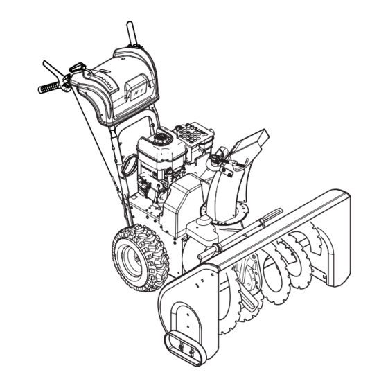
- Page 1 Model No. C950-52301-0 Dual Stage Snowthrower, 11.5 TP, 24 Inch CAUTION: Before using this product, read the manual and follow all its Safety Rules and Operating Instructions. Sears Canada Inc., Toronto, Ontario M5B 2C3 80006828 Revision - Visit our Craftsman website: www.sears.ca/craftsman...
- Page 2 Thank you for purchasing this quality-built CRAFTSMAN snowthrower. We’re pleased that you’ve placed your confidence in the CRAFTSMAN brand. When operated and maintained according to the instructions in this manual, your CRAFTSMAN product will provide many years of dependable service.
-
Page 3: Table Of Contents
Table of Contents Operator Safety ................Hazard Symbols and Meanings ..........Control Symbols on Equipment ..........Safety Alert Symbols and Signal Words ........Safety Decals ................Features and Controls ..............Snowthrower Controls ............... Engine Controls ................. Operation ..................Before Operating Snowthrower ..........Safety System Tests .............. -
Page 4: Operator Safety
Operator Safety Hazard Symbols and Meanings Thrown Fire Protection Objects Rotating Impeller Shock Moving Explosion Parts Surface Toxic Rotating Kickback Fumes Auger Safe Distance Hazardous Rotating Chemical Rotating Protection Parts Gears Control Symbols on Equipment Engine Slow On-Off Discharge Traction Chute Fast Fuel... -
Page 5: Safety Alert Symbols And Signal Words
Operator Safety Safety Alert Symbol and Signal Words WARNING The safety alert symbol and signal word (DANGER, WARNING, CAUTION, or NOTICE) is used to indicate the Read, understand, and follow all the likelihood and potential severity of personal injury and/or damage instructions on the snowthrower and in the to the product. - Page 6 Operator Safety DANGER WARNING Keep hands, feet, and clothing away from Objects can be picked up by auger and thrown rotating parts. Rotating parts can contact from chute. Never discharge snow toward or entangle hands, feet, hair, clothing, or bystanders or allow anyone in front of the accessories.
- Page 7 Operator Safety WARNING WARNING Fuel and its vapors are extremely flammable Safe operation of the snowthrower requires the and explosive. Always handle fuel with proper care and maintenance of the engine. extreme care. Failure to observe these safety instructions can cause a fire or explosion which will result in severe burns or death.
- Page 8 Operator Safety WARNING WARNING This snowthrower must be properly maintained This snowthrower is only as safe as the to ensure safe operation and performance. operator. If it is misused, or not properly Failure to observe the safety instructions in this maintained, it can be dangerous.
-
Page 9: Safety Decals
Operator Safety Safety Decals Before operating your snowthrower, read the safety decals If any safety decals become worn or damaged and cannot installed on your snowthrower. The cautions and warnings be read, order replacement decals from your local dealer. are for your safety. To avoid a personal injury or damage to your snowthrower, understand and follow all the safety de- cals. -
Page 10: Features And Controls
Features and Controls Figure 2 SNOWTHROWER CONTROLS E. Easy-Turn Traction Control — When engaged, allows the operator to release one drive wheel, but allows the other A. Speed Select Lever — Allows the operator to select forward wheel to continue driving for easy turning. and reverse speeds (see Figure 2). -
Page 11: Engine Controls
Features and Controls STOP Figure 3 SNOWTHROWER CONTROLS (Continued) E. Starter Cord Handle — Used to start the engine manually. J. Headlight — Used to operate the snowthrower in poor light- F. Fuel Tank and Cap — Fill the fuel tank to approximately ing conditions. -
Page 12: Operation
Operation BEFORE OPERATING SNOWTHROWER NOTE: This snowthrower was shipped WITH OIL in the engine. See “Before Starting Engine” instructions in the Operation Check the fasteners. Make sure all fasteners are tight. section of this manual before starting engine. Read this Operator’s Manual and Operator Safety before operating your snowthrower. -
Page 13: Stop The Snowthrower
Operation STOP THE SNOWTHROWER 1. Release the traction control lever (C, Figure 2). 2. Pull out the safety key (D, Figure 3). 3. Keep the safety key out of the reach of children. WARNING: Never run engine indoors or in an enclosed, poor ventilated area. -
Page 14: Check The Oil (Before Starting Engine)
Operation CHECK THE OIL (BEFORE STARTING EN- GINE) NOTE: The engine was shipped from the factory filled with oil. Check the level of the oil. Add oil as needed. 1. Make sure the unit is level. Use a high quality detergent oil classified “For Service SF, SH, SJ, SL, or higher”. -
Page 15: Adding Fuel
Operation ADDING FUEL Start the engine as follows: 1. Check the oil level. See Check the Oil section. WARNING 2. Make sure equipment drive controls are disengaged. Fuel and its vapors are extremely flammable 3. Insert the safety key (A, Figure 7) into the safety key slot and explosive. -
Page 16: Stop The Engine
Operation STOP THE ENGINE 7. Electric Start: First connect the extension cord to the power cord receptacle and then into a wall receptacle. If ad- Before stopping the engine for a few minutes to help dry off ditional extension cord is required, make sure it is three-wire. any moisture on the engine. -
Page 17: Clear A Clogged Discharge Chute
Operation OPERATING TIPS CLEAR A CLOGGED DISCHARGE CHUTE 1. Most efficient snowthrowing is accomplished when snow WARNING: Hand contact with the rotating is removed immediately after it falls. impeller inside the discharge 2. For complete snow removal, slightly overlap each swath pre- chute is the most common cause of injury viously taken. -
Page 18: Maintenance
Maintenance MAINTENANCE CHART SNOWTHROWER ENGINE After Each Use First 5 Hours Remove the snow and slush off snowthrower to prevent Change engine oil freezing of controls Every 8 Hours or Daily Every 8 Hours or Daily Check engine oil level Perform snowthrower safety tests Every 50 Hours or Annually * Every 25 Hours or Annually *... -
Page 19: Skid Shoe Height Adjustment
Maintenance This snowthrower is equipped with two height adjust skids, secured to the outside of the auger housing. These elevate the front of the snowthrower. When removing snow from a hard surface area such as a paved driveway or walk, adjust the skids up to bring the front of the Full snowthrower down. -
Page 20: Auger Control Cable Adjustment
Maintenance AUGER CONTROL CABLE ADJUSTMENT WARNING: Do not over-tighten, as this may lift the lever and cause the auger drive to be engaged without depressing the auger drive control. 1. With the auger control lever released, the hook (A, Figure 14) should barely touch the lever (B) without raising it. -
Page 21: Auger Shear Bolt Replacement
Maintenance AUGER SHEAR BOLT REPLACEMENT The augers are secured to the auger shaft with special bolts that are designed to break if an object becomes lodged in the auger housing. Use of a harder bolt will reduce the protection provided by the shear bolt. -
Page 22: Off-Season Storage
Maintenance OFF-SEASON STORAGE • Thoroughly clean the unit. • Lubricate all lubrication points (see authorized dealer). If the unit will be stored for thirty (30) days or more at the end of the season, the following steps are recommended to prepare it •... -
Page 23: Troubleshooting
Troubleshooting PROBLEM LOOK FOR REMEDY Auger does not stop Free-Hand™ control is Release both auger control and traction/Free-Hand™ control within 5 seconds after ACTIVE. levers to stop auger. right control lever is Free-Hand™ control is See authorized dealer. released. not working correctly (fails Safety Test 3). - Page 24 Troubleshooting PROBLEM LOOK FOR REMEDY Snowthrower forward Traction control out of See authorized dealer. adjustment (fails Safety and reverse motion does not stop when Test 2). traction control lever is released. Snowthrower veers to Tire pressure not equal. Check tire pressure. one side.
-
Page 25: Warranties
Craftsman Limited Warranty General: Craftsman products are warranted to be free from defects in materials or workmanship for a specific time pe- riod as set-out below (the “Warranty Period”). Warranties extend to the original purchaser of a Craftsman product only. -
Page 26: Maintenance Agreement
Warranties 3. 1 year: Craftsman power cutters, stump grinders, pole pruners, gas chain saws, electric chain saws, trimmer attach- ments, baggers and pole saws for noncommercial, nonprofessional, non-institutional, or non-income-producing use. 4. 90 days: All defective batteries, which will be replaced during this 90-day Warranty Period. -
Page 28: Specifications
Specifications ENGINE: Brand Briggs & Stratton® Model Series Professional Series Gross Torque 11.5 T.P. @ 3060 rpm Type 4-Cycle - OHV Displacement 15.26 cu in. (250 cc) Starting System Recoil, 110V Electric w/Cord Alternator 9 Amp Reg Spark Plug Gap 0.030 in. -
Page 29: Repair Parts
Repair Parts PTS - 1... - Page 30 Handles & Controls Group CRAFTSMAN 24" C950-52301-0 NOTE: Unless noted otherwise, use the standard hardware torque specification chart. PTS - 2...
- Page 31 Handles & Controls Group CRAFTSMAN 24" C950-52301-0 REF NO PART NO. QTY. DESCRIPTION 0010 1923701SM CAPSCREW, Hex Head, 3/8-16 x 2, GR5 0050 50786MA SPRING, 1/2 Dia. x 3/4 0060 1918266SM WASHER, 3/8 x 13/16 OD 0070 1919439SM NUT, Hex Lock, ESNA Light, 3/8-16...
- Page 32 Handles & Controls Group CRAFTSMAN 24" C950-52301-0 NOTE: Unless noted otherwise, use the standard hardware torque specification chart. PTS - 4...
- Page 33 Handles & Controls Group CRAFTSMAN 24" C950-52301-0 REF NO PART NO. QTY. DESCRIPTION 0560 1737511YP CABLE, Traction Drive 0590 1733505ASM BRACKET, Pivot, Free Hand 0600 1733095SM SPACER, Powdered Metal 0610 1736363YP ROD & SPRING ASSEMBLY 0630 2108360SM SPRING, Compression, 017/32 ID x 2-1/4 Lg...
- Page 34 Engine & Frame Group CRAFTSMAN 24" C950-52301-0 NOTE: Unless noted otherwise, use the standard hardware torque specification chart. PTS - 6...
- Page 35 Engine & Frame Group CRAFTSMAN 24" C950-52301-0 REF NO PART NO. QTY. DESCRIPTION 0010 15C114-0153-F8 * ENGINE, 11.5TP Briggs & Stratton (Engine Model: 15C114-0153-F8) 0010-10 792647 CAP, Fuel 0010-20 797003 GUARD, Muffler (Incl. Ref. No. 0010-30) 0010-30 810214 SCREW, Tapping, Hex Washer Head...
- Page 36 Auger Drive Group CRAFTSMAN 24" C950-52301-0 NOTE: Unless noted otherwise, use the standard hardware torque specification chart. PTS - 8...
- Page 37 Auger Drive Group CRAFTSMAN 24" C950-52301-0 REF NO PART NO. QTY. DESCRIPTION 0070 704363 GEAR CASE ASSEMBLY 0080 2001022MA KEY, Square, 3/16 x 3/4 0090 1739094AYP IMPELLER 0100 1739073YP HUB, Impeller 0110 1930601SM SCREW, Hex Washer Head, Taptite, 5/16-18 x 5/8...
- Page 38 Auger Housing Group CRAFTSMAN 24" C950-52301-0 NOTE: Unless noted otherwise, use the standard hardware torque specification chart. PTS - 10...
- Page 39 Auger Housing Group CRAFTSMAN 24" C950-52301-0 REF NO PART NO. QTY. DESCRIPTION 0010 1687773YP HOUSING, Auger, 24" 0020 1736620YP CLAMP 0030 1960569SM SCREW, Truss Head Torx, #10-24 x 3/8 0040 15X146MA NUT, Nylock, 10 x 24 0060 1736094YP BRUSH, Cleanout...
- Page 40 Traction Drive Group CRAFTSMAN 24" C950-52301-0 NOTE: Unless noted otherwise, use the standard hardware torque specification chart. PTS - 12...
- Page 41 Traction Drive Group CRAFTSMAN 24" C950-52301-0 REF NO PART NO. QTY. DESCRIPTION 0200 1733972YP * TRANSMISSION, General Transmission H2 0210 1737267AYP BRACKET 0220 7091557SM CAPSCREW, Hex Head, 3/8C x 2-3/4 GR5 0230 1960251SM NUT, Hex Jam, 3/8-16 0240 1737330YP ROD, Speed Select...
- Page 42 Transmission SERVICE PARTS - General Transmission H2 CRAFTSMAN 24" C950-52301-0 NOTE: Unless noted otherwise, use the standard hardware torque specification chart. PTS - 14...
- Page 43 Transmission SERVICE PARTS - General Transmission H2 CRAFTSMAN 24" C950-52301-0 REF NO PART NO. QTY. DESCRIPTION 0200 1733972YP TRANSMISSION, Complete General Transmission H2 0200-1 1739646YP SPRING, Traction, 8.75 Inches 0200-2 1739645YP SCREW, 5 X 25 0200-3 1739641YP WASHER, 5.3 X 15 X 1.2.ipt...
- Page 44 Wheels & Tires Group CRAFTSMAN 24" C950-52301-0 NOTE: Unless noted otherwise, use the standard hardware torque specification chart. PTS - 16...
- Page 45 Wheels & Tires Group CRAFTSMAN 24" C950-52301-0 REF NO PART NO. QTY. DESCRIPTION 0010 1754243YP WHEEL & TIRE ASSEMBLY, 4.80-8, LH (Includes Ref. 0010-20) 0020 1754245YP WHEEL & TIRE ASSEMBLY, 4.80-8, RH (Includes Ref. 0010-20) 0010-20 2172353SM VALVE STEM & CAP...
- Page 46 Decals Group CRAFTSMAN 24" C950-52301-0 NOTE: Unless noted otherwise, use the standard hardware torque specification chart. PTS - 18...
- Page 47 Decals Group CRAFTSMAN 24" C950-52301-0 REF NO PART NO. QTY. DESCRIPTION 0040 1737865YP DECAL, Danger Chute, FR/ENG 0050 1737866YP DECAL, Danger Foot, FR/ENG 0060 1737869YP DECAL, Auger Control Symbols 0070 1737870YP DECAL, Traction Control Symbols 0080 1754679YP DECAL, Handle Operation...
- Page 48 Discharge Chute Group CRAFTSMAN 24" C950-52301-0 NOTE: Unless noted otherwise, use the standard hardware torque specification chart. PTS - 20...
- Page 49 Discharge Chute Group CRAFTSMAN 24" C950-52301-0 REF NO PART NO. QTY. DESCRIPTION 0010 1728967SM PINION 0030 1739621YP SCREW, Torx Button Head, M5 x .8 x 14 0035 7091552SM WASHER, Flat, 1/4 0040 1925592SM SCREW, Hex Washer Head, Taptite, 1/4-20 x 3/4...
- Page 50 15C114- -0151- -F8 48 SHORT BLOCK 1058 OPERATOR’S MANUAL 1329 REPLACEMENT ENGINE 1330 REPAIR MANUAL 1036 EMISSIONS LABEL 307A 1427 MSC000678- 2 Assemblies include all parts shown in frames. 09/16/2013...
- Page 51 15C114- -0151- -F8 REF. PART REF. PART REF. PART DESCRIPTION DESCRIPTION DESCRIPTION 794188 Cylinder Assembly 791784 Screw (Governor 796961 Kit--Bushing/Seal (Connecting Rod) Control Lever) (Magneto Side) 693404 Camshaft 791759 Cover-- 299819s Seal--Oil Short Block Breather Passage (Magneto Side) (Not Available 791760 Gasket-- 699485 Gasket--Crankcase At This Printing)
- Page 52 15C114- -0151- -F8 914A 1026 1023 1022 1029 1022 1034 MSC000678- 4 Assemblies include all parts shown in frames. 09/16/2013...
- Page 53 15C114- -0151- -F8 REF. PART REF. PART REF. PART DESCRIPTION DESCRIPTION DESCRIPTION 791720 Head--Cylinder 791717 Spacer--Carburetor 699481 Screw 791716 Gasket--Cylinder Head 797442 Plate--Cylinder Head (Rocker Cover) 699482 Screw 797440 Adjuster--Rocker Arm (M6x15.8mm) (Cylinder Head) 691300 Cap--Valve 914A 797444 Screw 499642 Valve--Exhaust 691043 Plug--Spark (Rocker Cover) 795443 Valve--Intake...
- Page 54 15C114- -0151- -F8 187A MSC000678- 6 Assemblies include all parts shown in frames. 09/16/2013...
- Page 55 15C114- -0151- -F8 REF. PART REF. PART REF. PART DESCRIPTION DESCRIPTION DESCRIPTION 791718 Gasket--Intake 791717 Spacer--Carburetor 797632 Washer--Sealing 590907 Carburetor 798649 Screw 791718 Gasket--Intake 691636 Screw 797633 Plug--Welch (Mounting Bracket) 699484 Screw (Throttle Valve) 797630 Valve--Throttle 797628 Shaft--Throttle 797136 Float--Carburetor (Carburetor) 791948 Knob--Choke Shaft 797156 Kit--Idle Speed...
- Page 56 15C114- -0151- -F8 1230 1119 1054 493A MSC000678- 8 Assemblies include all parts shown in frames. 09/16/2013...
- Page 57 15C114- -0151- -F8 REF. PART REF. PART REF. PART DESCRIPTION DESCRIPTION DESCRIPTION 693389 Rope--Starter 796964 Armature--Magneto 698039 Cover--Starter Drive 690837 Screw 699477 Screw 699200 Screw (Rewind Starter) (Magneto Armature) (Starter Drive Cover) (#10--32x.27mm) 699334 Kit--Rope/Handle 795901 Cord--Starter 699479 Screw 698314 Alternator 690635 Clamp (Control Bracket) 493A...
- Page 58 15C114- -0151- -F8 731A 1196A 604A 1196 1252 1251A 1070 1005 1252A 1251 MSC000678- 10 Assemblies include all parts shown in frames. 09/16/2013...
- Page 59 15C114- -0151- -F8 REF. PART REF. PART REF. PART DESCRIPTION DESCRIPTION DESCRIPTION 695745 Tube--Breather 790473 Cover--Control 1070 699201 Screw 798882 Flywheel 604A 793134 Cover--Control (Flywheel Fan) 699661 Guard--Flywheel 794614 Arrestor--Intake 1196 699854 Screw 699228 Screw 791972 Screw (Snow Hood) (Rewind Starter) (Muffler) (M5x10.8mm) (M5x6.3mm)
- Page 60 15C114- -0151- -F8 121 CARBURETOR OVERHAUL KIT 127A 276A 163A 137A 633A 358 ENGINE GASKET SET 1022 1095 VALVE GASKET SET 1022 MSC000678- 12 Assemblies include all parts shown in frames. 09/16/2013...
- Page 61 15C114- -0151- -F8 REF. PART REF. PART REF. PART DESCRIPTION DESCRIPTION DESCRIPTION 299819s Seal--Oil 792006 Kit-- 691321 Seal-- (Magneto Side) Carburetor Overhaul Choke/Thottle Shaft 698210 Gasket--Cylinder Head 127A 691739 Plug--Welch 633A 693867 Seal-- 699485 Gasket--Crankcase 398188 Kit--Needle/Seat Choke/Thottle Shaft 692550 Seal--Oil 137A 798932 Gasket--Float Bowl 691893 Gasket--Exhaust...
- Page 62 PTS - 34...
- Page 63 11,5 couple de puissance, 24 pouces MISE EN GARDE : Avant d’utiliser ce produit, lire le manuel et suivre toutes ses consignes de sécurité et ses instructions d’utilisation. Sears Canada Inc., Toronto, Ontario M5B 2C3 Consulter le site Web de Craftsman : www.sears.ca/craftsman...
- Page 64 Merci d’avoir acheté cette souffleuse à neige CRAFTSMAN. Nous sommes heureux que vous ayez placé votre confiance dans la marque CRAFTSMAN. Si vous utilisez et entretenez ce produit CRAFTSMAN conformément aux instructions du manuel, vous pourrez l’utiliser pendant de nombreuses années.
- Page 65 Table des matières Sécurité de l’utilisateur ..............Symboles de risque et leur signification ..........4 Symboles de contrôle sur l’équipement ...........4 Symboles d’alerte de sécurité et mots-indicateurs ......5 Autocollants de sécurité ..............9 Fonctions et commandes ............. Commandes de la souffleuse à neige ...........10 Commandes du moteur ..............11 Fontionnement ................
-
Page 66: Sécurité De L'utilisateur
Sécurité de l’utilisateur Symboles de risque et leur signification Protection Objets Feux des yeux projetés Impulseur rotatif Choc Pièces Explosion amovibles Surface chaude Vapeurs Tarière Effet de toxiques rotative recul Distance de sécurité Produits Protection Pièces chimiques Engrenages des oreilles tournantes dangereux rotatifs... -
Page 67: Symboles D'alerte De Sécurité Et Mots-Indicateurs
Sécurité de l’utilisateur Symboles d’alerte de sécurité et mots-indicateurs AVERTISSEMENT Le symbole d’alerte de sécurité et mot de signalisation Lisez, comprenez et suivez toutes les instruc- (DANGER, AVERTISSEMENT, MISE EN GARDE ou AVIS) sont tions sur la souffleuse à neige dans le manuel utilisés pour indiquer la probabilité... - Page 68 Sécurité de l’utilisateur AVERTISSEMENT AVERTISSEMENT Gardez les mains, les pieds et les vêtements Les objets peuvent être ramassés par la loin des pièces rotatives. Les pièces rotatives tarière et projetés du conduit. Ne rejetez peuvent contacter ou enchevêtrer les mains, jamais de la neige vers des spectateurs et ne les pieds, les cheveux, les vêtements ou ac- permettez à...
- Page 69 Sécurité de l’utilisateur AVERTISSEMENT AVERTISSEMENT Le carburant et ses vapeurs sont extrêmement Le fonctionnement sans danger de la souf- inflammables et explosifs. Veuillez bien prendre fleuse à neige demande un soin et entretien soin avec précaution du carburant. vigilant. Le fait de ne pas observer ces instructions de sécurité...
- Page 70 Sécurité de l’utilisateur AVERTISSEMENT AVERTISSEMENT Cette souffleuse à neige doit être proprement Cette souffleuse à neige est aussi sûre que entretenue pour assurer un fonctionnement et son utilisateur puisse l’être. Si mal utilisé ou une performance en toute sécurité. La faillite mal entretenu, ceci peut être dangereux.
-
Page 71: Autocollants De Sécurité
Sécurité de l’utilisateur Autocollantes de sécurité Avant de mettre en marche votre souffleuse à neige, lisez Si n’importe quelle décalcomanie de sécurité devient usée les étiquettes autocollantes de sécurité sur votre souffleuse ou endommagée et ne peut être lu, commandez des décal- à... -
Page 72: Fonctions Et Commandes
Fonctions et commandes Figure 2 COMMANDES DE LA SOUFFLEUSE À NEIGE E. Commande de traction Easy Turn™ — Quand elle est em- A. Levier de changement de vitesse — Permet à l’utilisateur brayée, permet à l’utilisateur de débrayer une roue tractrice de sélectionner les vitesses avant et arrière (voir Figure 2). -
Page 73: Commandes Du Moteur
Fonctions et commandes STOP Figure 3 COMMANDES DE LA SOUFFLEUSE À NEIGE (Suite) E. Cordon de démarreur — Utiliser pour mettre en marche le J. Phares — Utiliser pour faire fonctionner la souffleuse à neige moteur manuellement. dans des conditions de pauvre visibilité. F. -
Page 74: Avant D'utilisation Souffleuse À Neige
Fonctionnement AVANT D’UTILISATION SOUFFLEUSE À NEIGE REMARQUE : Cette souffleuse à neige est livrée AVEC DE L’HUILE dans le moteur. Voir les instructions « Avant de Contrôler la visserie. Vérifier que toute la visserie est démarrer le moteur » dans la section Fonctionnement de ce bien serrée. -
Page 75: Arrêter La Souffleuse À Neige
Fonctionnement ARRÊTER LA SOUFFLEUSE À NEIGE 1. Relâcher le levier de commande de traction (C, Figure 2). 2. Sortir la clé de sécurité (D, Figure 3). 3. La maintenir hors de portée des enfants. AVERTISSEMENT : Ne jamais faire tourner le moteur a l’intérieur ou dans des endroits clos et mal ventilés. -
Page 76: Contrôler Le Niveau D'huile (Avant De Démarrer Le Moteur)
Fonctionnement CONTRÔLER LE NIVEAU D’HUILE (AVANT DE DÉMARRER LE MOTEUR) REMARQUE : Le moteur est livré d’usine rempli d’huile. Contrôler le niveau d’huile. Compléter le niveau le cas échéant. 1. S’assurer que la machine est de niveau. Utiliser une huile détergente de haute qualité... -
Page 77: Plein D'essence
Fonctionnement PLEIN D’ESSENCE Démarrer le moteur comme suit : 1. Vérifiez le niveau d’huile. Veuillez voir la section « Contrôler AVERTISSEMENT le niveau d’huile. » Le combustible et ses vapeurs sont 2. Assurez-vous que les commandes d’entraînement de extrêmement inflammables et explosifs. l’équipement sont débrayées. -
Page 78: Arrêt Le Moteur
Fonctionnement ARRÊT LE MOTEUR 7. Démarrage électrique : Connecter d’abord la rallonge à la prise du cordon d’alimentation et ensuite dans une prise Avant d’arrêter le moteur, laissez-le fonctionner pour quelques murale. Si un autre cordon de raccordement est nécessaire, minutes pour sécher l’humidité... -
Page 79: Dégagement De L'éjecteur Bloqué
Fonctionnement DÉGAGEMENT DE L’ÉJECTEUR BLOQUÉ CONSEILS DE FONCTIONNEMENT 1. L’enlèvement efficace de la neige est accomplie lorsque la DANGER : Le contact des mains avec l’impulseur neige est enlevée immédiatement après la tombé. rotatif dans le conduit d’éjection est la cause 2. -
Page 80: Entretien
Entretien TABLEAU DE MAINTENANCE MOTEUR SOUFFLEUSE À NEIGE Les 5 premières heures Après chaque utilisation Changer l’huile du moteur Retirer la neige et débourber la souffleuse à neige pour éviter le gel des commandes Toutes les 8 heures ou chaque jour Toutes les 8 heures ou chaque jour Vérifier le niveau d’huile du moteur Effectuer les tests de sécurité... -
Page 81: Réglage De La Hauteur Des Patins
Entretien Cette souffleuse à neige est munie avec deux patins ajustables pour hauteur, attachez à l’extérieur du boîtier de la tarière. Ceux- ci élèvent le devant de la souffleuse à neige. Lors de l’enlèvement de la neige d’une surface dur tels que les voies d’accès ou les trottoirs pavés, ajuster les patins vers le haut pour incliner le devant de la souffleuse à... -
Page 82: Réglage Du Câble De Commande De La Tarière
Entretien RÉGLAGE DU CÂBLE DE COMMANDE DE LA TARIÈRE AVERTISSEMENT : Ne resserrez pas trop, car ceci peut lever le levier et causer l’entraînement de la tarière à être embrayé sans la dépression du levier de commande de la tarière. 1. -
Page 83: Remplacement Du Boulon De Cisaillement Pour Tarière
Entretien REMPLACEMENT DU BOULON DE CISAILLEMENT POUR TARIÈRE Les tarières sont fixées à l’arbre de la tarière avec des boulons spéciaux de cisaillement qui sont conçues pour briser si un objet devient pris dans le boîtier de la tarière. L’utilisation d’un boulon plus dur réduira la nécessité... -
Page 84: Remisage Hors Saison
Entretien REMISAGE HORS SAISON • Nettoyer soigneusement la machine. • Lubrifier tous les points de lubrifications (voir la section Si la machine doit être remisée pendant trente (30) jours Entretien). ou plus à la fin de la saison, les étapes suivantes sont recommandées pour la préparer pour le remisage. -
Page 85: Dépannage
Dépannage PROBLÈME VÉRIFIEZ QUE SOLUTION La tarière s’arrête dans La commande Free-Hand™ est Relâchez à la fois la commande de tarière et les les 5 secondes suivant le ACTIVE. leviers de commande de traction/Free-Hand™ pour relâchement du levier de arrêter la tarière. commande droit. - Page 86 Dépannage PROBLÈME VÉRIFIEZ QUE SOLUTION La souffleuse à neige en Commande de traction déréglée Consultez un revendeur agréé. marche avant ou arrière ne (ne réussit pas à passer le test s’arrête pas quand le levier de sécurité 2). de commande de traction est débrayé.
-
Page 87: Garanties
(la « période de garantie »). En outre, cette garantie est offerte uniquement à l’acheteur initial du produit Craftsman. Les achats effectués par l’entremise d’un encan en ligne ou sur tout site Web autre que www.sears.ca sont exclus. - Page 88 Liste des périodes de garantie applicables : La liste ci-dessous indique la période de garantie applicable aux div- ers produits Craftsman qu’elle couvre; la période accordée tient compte du type de produit ou de composants et du type d’utilisation prévue ou effective de l’appareil ou du composant : 1.
-
Page 90: Spécifications
Spécifications MOTEUR : Marque Briggs & Stratton® Séries du modèle Professional Series Couple de serrage brut 11,5 T.P. @ 3060 rpm Type 4-Cycle - OHV 250 cc (15,26 po Cylindrée Démarrage du système Lanceur, Électrique 110V w/Cord Alternateur 9 Amp Reg Écartement des électrodes 0,76 mm (0,030 in.) Capacité...
Need help?
Do you have a question about the C950-52301-0 and is the answer not in the manual?
Questions and answers
Front drive cable replacement