
Subscribe to Our Youtube Channel
Related Manuals for Craftsman C950524312A


Summary of Contents for Craftsman C950524312A
- Page 1 S _ARS Owners manual DUAL STAG Model SNOW BLOWER C950524312A 11.5 H.P, 30 inch CAUTION: You must read and understand this owner's manual before operating unit. Serial No. 401428 SEARS CANADA INC., TORONTO, ONTARIO M5B 2B8 Printed i nU.S.A.
-
Page 2: Hazard Symbols And The Meanings
RULES FOR SAFE OPERATION General Information HazardSymbolsend the meanings Thisinstruction book iswritten fora person with some mechanical ability. Thesesymbols a reused onyour equipment anddefined inYour o perating Ukemostservice books, notallthesteps aredescribed. Stepson how to manual. Review andunderstand themeanings. Theuseofoneof these loosen ortighten fasteners arestepsanyone c anfollowwith some symbols c ombined with a signal w ord willalert youtopotential hazards mechanical ability. -
Page 3: Operatingsymbolsand Their Meanings
RULES FOR SAFE OPERATION OperatingSymbolsand their meanings These symbols are usedon yourequipment e nddefinedin youroperating _kDANGER manuel. It is important t hat youreviewand understand the meanings. Failureto understand the symbolsmightresultin harmto you. • Neverattempttodearaugerofdebds orclogged s nowwhJe equipment is engaged orengine is running. Clogged orblocked a ugers storeenergy Forward andcanrotate unexpectedly, EVEN WITHENGINE OFf Fuel... - Page 4 RULES FOR SAFE OPERATION _I=DANGER ,_WARNING WHEN ADDING FUEL • Turn engine OFFandletengine cool a t least2 minutesbefore removing • Beaware ofyour e nvironment whileoperating e quipment. Running o ver gascap. items suchas,gravel, d oormats, newspapars, toys, a ndrocks hidden •...
-
Page 5: Owner's Information
3. Tire replacement or repair caused by puncturesfrom outside objects, such as nails, thorns, stumps or glass. 4. In home service. Warranty service is available by returning the Craftsman snow blower to the nearest Sears Service Centre/Department in Canada. This warranty applies only while this product is in use in Canada. -
Page 6: Table Of Contents
TABLE OF CONTENTS HAZARD SYMBOLS AND THE MEANINGS ..OPERATING TIPS ......OPERATING SYMBOLS AND THEIR MEANINGS ..SERVICE RECOMMENDATIONS ....OWNER'S INFORMATION ......CUSTOMER RESPONSIBILITIES ....ASSEMBLY ........SNOW BLOWER ....... TOOLS REQUIRED FOR ASSEMBLY ....LUBRICATION AT STORAGE ....CONTENTS OF SHIPPING CARTON .... -
Page 7: Assembly
ASSEMBLY TOOLS REQUIRED FOR ASSEMBLY CONTENTS OF SHIPPING CARTON 1 - Knife 1- Snow Blower 2 - 1/2" wrenches (or adjustable wrenches) 1- Container of Fuel Stabilizer (Located in Parts Bag) 2 - 9/16" wrenches (or adjustable wrenches) 1- Snow Chute Assembly 2 - 3/4"... -
Page 8: Unpacking
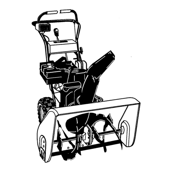
ASSEMBLY Figure 1 shows the snow blower in the shippingposition. Figure 2 shows the snow blower completely assembled. Reference to right and left hand side of the snow blower is from the operator's position at the handle. UNPACKING Locate the two tear tabs at the bottom of the carton, Auger Drive Traction Drive Pull the tear tape no more than twelve inches (30.48cm.) -
Page 9: Upper Handle And Crankassembly
ASSEMBLY UPPER HANDLE AND CRANKASSEMBLY Adaptor Boot! Loosen, but do not remove the screws, flatwashers, lock- washers and hex nuts in the upper holes of the lower han- Flatwashe_ Lockwasher_ dle. Locknut Remove the fasteners and the crank assembly eyebolt from the lower holes of the lower handle. -
Page 10: Speed Select Lever
ASSEMBLY SPEED SELECT LEVER Cut plastic tie securing speed select lever assembly to the shifter bracket. (See Figure 7) Shifter Bracke_ Remove Iocknut, washer, spring, and the bolt. (See Figure 9) Position speed selector lever assembly as shown in Figure 8. Reinstall bolt, spring, washer and Iocknut. -
Page 11: Snow Chute Assembly
ASSEMBLY SNOW CHUTE ASSEMBLY Positionthe snow chute onto the snow chute flange, Al- ign the three holes in the snow chute with holes in snow Chute Extension chute flange. (See Figure 10) Snow Chute Deflector Place three 5/16-18 carriage boltsfrom inside of chute as shown in Figure 10. -
Page 12: Operation
OPERATION Get to know your snow blower and its controls. Be sure you (or any other operator) have read and understoodthe Operation Precautions listed on page 2 of this manual. Choke Gas Tank Auger Drive Traction Drive Control Clutch Lever Clutch Lever Primer Button Traction Ddve... -
Page 13: Snow Blower Operation
OPERATION The operation of any snow blower can result in foreign objects being thrown into the eyes,which can result in severe eye damage. Always wear safety glasses or eye shields before beginning snow blower Operation. We recommend standard safety glasses or Wide Vision Safety Mask for over spectacles. SNOW BLOWER OPERATION WARNING: Read Owner's Manual before oper- ating machine. -
Page 14: Wheel Lock Out Pin
OPERATION WHEEL LOCK OUT PIN 1. The rightwheel is secured to the axle with a klickpin. This unit was shipped with this klick pin in the locked position. (Figure 14). For ease of maneuverability when lighter conditions pre- vail, remove klick pin from wheel locked position and in- into single wheel... -
Page 15: Before Starting Engine
OPERATION BEFORE STARTING ENGINE Fill the fuel tank with fresh, clean, unleaded regular, un- leaded premium, or reformulated automotive gasoline Check the oil with a minimum of 85 octane along with a fuel stabilizer (follow instructions on fuel stabilizer package). DO NOT NOTE: The engine was shipped from the factory filled use leaded gasoline. -
Page 16: Before Stopping The Engine
OPERATION BEFORE STOPPING THE ENGINE Run the engine for a few minutes to help dry off any moisture on the engine. TO STOP ENGINE CAUTION: To stop the engine, do not move the choke Pull out the safety key. control to CHOKE position. Backfire or engine damage can occur. - Page 17 OPERATION Choke Knob Primer Safety Key Starter Motor Recoil Starter Handle Stop Switch Figure 19 How To Start A Cold Engine If the engine does not start in 5 or 6 tries, See Difficult Be sure auger drive and traction drive levers are in the Starting in the 'Troubleshooting Table".
-
Page 18: Frozen Starter
OPERATION FROZEN STARTER closed, poorly ventilated areas. Engine exhaust WARNING: Never run engine indoors or In en- If the starter is frozen and will not turn engine: contains CARBON MONOXIDE, AN ODORLESS Pull as much rope out of the starter as possible. AND DEADLY GAS. -
Page 19: Operating Tips
OPERATION OPERATING TIPS Most efficient snowblowingis accomplished when snow After the snowblowing job has been completed, allow the is removed immediately after it falls. engine to idle for a few minutes, to melt snow and ice ac- cumulated on the engine. For complete snow removal, slightly overlap each swath previously taken. -
Page 20: Service Recommendations
SERVICE RECOMMENDATIONS SERVICE RECOMMENDATIONS FIRST BEFORE EVERY EVERY EVERY EVERY EVERY BEGINNING PROCEDURE EACH EACH BEFORE HOUR HOURS HOURS HOURS HOURS HOURS SEASON STORAGE ]]ghtenall screwsand nuts Check Traction Clutch Cable Ad ustment See Cab e Ad ustment) Check Auger clutch Cable \d ustment See Cab e Ad ustment) Adjust Drive Belts... -
Page 21: Customer Responsibilities
CUSTOMER RESPONSIBILITIES Some adjustments will need to be made periodically to properly maintain your snow blower. All adjustments in ADJUSTMENTS/REPAIRS section of this manual should be checked at least once each season. SNOW BLOWER The following adjustment should be performed more than once each season. -
Page 22: Lubrication - Every 25 Hours
CUSTOMER RESPONSIBILITIES LUBRICATION - EVERY 25 HOURS Chute Rotation Gear Lubricatethe chute rotation gear with automotivetype oil, (see Figure 23). Figure 22 Chains Lubricate the chains with a chain type lubricant. Wipe the hexshaft and sprockets with 5W30 motoroil, 1. Position speed selector lever in first (1) forward gear. Stand the snow blower up on the auger housing end. -
Page 23: Engine
CUSTOMER RESPONSIBILITIES ENGINE TEMPERATURE TYPE OF OIL 0°F (-18 ° C) and above S.A.E. 5W30 POWER RATINGS 0°F (-18 ° C) and below synthetic 5W30 The power ratingsfor an individualengine model are initially developed by starting with SAE (Society of Automotive SAE VISCOSITY GRADES Engineers) code J1940 (Small Engine Power &... -
Page 24: Adjustment/Repair
ADJUSTMENT/REPAIR To adjust skids, proceed as follows: WARNING: Always turn unit off, remove igni- tion key and disconnect the spark plug wire be- Place a block (equal to height from ground desired) un- fore making any repairs or adjustments. der scraper bar near but not under skid. AUGER HOUSING HEIGHT ADJUSTMENT Loosen skid mounting nuts (Figure 27) and push the skid TO ADJUST SCRAPER BAR... -
Page 25: How To Remove The Snow Hood
ADJUSTMENT/REPAIR HOW TO REMOVE THE SNOW HOOD Mounting Screws To access the spark plug, the snow hood must be removed Snow Hood as follows: Remove the choke control knob (see Figure 28). Spark Plug Remove the safety key. Remove the mounting screws (see Figure 29). Slowly remove the snow hood. -
Page 26: Beltadjustment
ADJ USTMENT/REPAIR BELT ADJUSTMENT Traction Drive Belt The tractiondrive belt has constant springpressure and does not require an adjustment. If the traction drive belt is slipping, replace the belt. See "How To Replace The Belts" in the Maintenance section. Auger Drive Belt If your snowthrower will not discharge snow, check the control cable adjustment. -
Page 27: How To Replace The Belts
ADJUSTM ENT/RI=PAIR HOW TO REPLACE THE BELTS The drive belts are of special construction and must be 16. Install the belt cover. Tighten screw (See Figure 32). replaced with original factory replacement belts available 17. Check the adjustment ofthe cables. See "How To Check from your nearest authorized service center. - Page 28 ADJUSTMENT/REPAIR Belt Guide Auger Drive Pulley Auger Drive Belt Traction Drive Spring Traction Drive Belt Traction Drive Pulley Swing Plate Axle Rod Engine Pulley Figure 36...
- Page 29 ADJ USTM ENT/R EPAIR How To Remove the Traction Drive Belt If the snow thrower will not move forward, check the traction 11. Install and adjust the auger drive belt. See =HowTo Re- drive belt for wear or damage. If the traction drive belt is worn move The Auger Drive Belt"in the Maintenance section.
-
Page 30: Belt Guide Adjustment
ADJUSTMENT/REPAIR BELT GUIDE ADJUSTMENT Remove spark plug wire. Have someone engage auger drive. -'_O// BeltGuide Measure the distance between the belt guide and belt. The distance should be 1/8 inch (3.175 mm) for guide. See Figure 38. If adjustment is necessary, loosen belt guide mounting bolt. -
Page 31: Traction Drive Cable Adjustment
ADJUSTMENT/REPAIR Traction Drive Cable Adjustment from fire or flame. ARNING: Drain the gasoline outdoors, away Remove the gas from the gas tank. Stand the snow thrower up on the front end of the auger housing. Loosen the bolts on each side of the bottom panel (see Figure 41). -
Page 32: How To Adjust Or Replace The Friction Wheel
ADJUSTMENT/REPAIR HOW TO ADJUST OR REPLACE 5. Tighten the jam nut. THE FRICTION WHEEL Install the bottom panel (see Figure 44). How To Check The Friction Wheel If the snow thrower will not move forward, check the traction drive belt, the traction drive cable or the friction wheel. If the 7. - Page 33 ADJUSTMENT/REPAIR How To Replace The Friction Wheel If the friction wheel isworn or damaged, the snow thrower will not move forward. The friction wheel must be replaced as follows. Remove the gas from the gas tank. Stand the snow thrower up on the front end of the auger housing (4), (see Figure 44).
- Page 34 ADJUSTMENT/REPAIR 10. Remove the three fasteners that holdthe friction wheel to the hub (see Figure 50). 11. Remove the friction wheel from the hub. Slip the fric- tion wheel off the hex shaft. 12. Assemble the new friction wheel onto hub with the fas- teners removed earlier.
-
Page 35: Auger Shear Bolt Replacement
ADJUSTMENT/REPAIR AUGER SHEAR BOLT REPLACEMENT The augers are secured to the auger shaftwith special bolts NOTE: For the operator's convlence, the shear bolt that are designed to break if an object becomes lodged in the wrenches are located in the toolbox. auger housing. -
Page 36: Storage
STORAGE OFF SEASON STORAGE Thoroughly clean the snow blower. ARNING: Never store engine with fuel in tank indoors or in enclosed, poorly ventilated enclo- Lubricate all lubrication points (see Lubrication, see Cus- sures, where fuel fumes may reach an open tomer Responsibilities). -
Page 37: Trouble Shooting Chart
TROUBLE SHOOTING CHART PROBLEM LOOK FOR REMEDY Difficult starting Defective spark plug. Replace defective spark ptug. Engine runs erratically Blocked fuel line. Clean fuel line. Empty gas tank. Check fuel supply, Stale gasoline. Add fresh gasoline with fuel stabilizer. Water or dirt in fuel system. Remove carburetor bowlto drain fuel tank. - Page 38 CRAFTSMAN 30" SNOW BLOWER C950524312A REPAIRPARTS CRAFTSMAN 30" CHASSE NEIGE C950524312A PIECESDE RECHANGE ENGINE / MOTEUR 25-2 20 / 25-1 25-3 25-4 25-2 Ref. Drive Page Ref. Auger Housing Page...
-
Page 39: Repair Parts
REPAIR PARTS CRAFTSMAN 30" SNOW BLOWER C950524312A PIECES DE RECHANGE CRAFTSMAN 30" CHASSE NEIGE C950524312A ENGINE / MOTEUR Key No. NO8ur le Part sch6ma N° de piTce Description Description 6219 CORD, STARTER CORDE DU DEMARREUR ..ENGINE MOTEUR 002x97 BOLT, CARRIAGE 5/16-18 BOULON, PO. - Page 40 REPAIR PARTS CRAFTSMAN 30" SNOW BLOWER C950524312A PII=CES DE RECHANGE CRAFTSMAN 30" CHASSE NEIGE C950524312A FRAME / BATI 1(36 Ref. Engine Page _ q_ _ Ref. Auger Housing Page Ref. Drive Page 122 _...
- Page 41 REPAIR PARTS CRAFTSMAN 30" SNOW BLOWER C950524312A PIECES DE RECHANGE CRAFTSMAN 30" CHASSE NEIGE C950524312A FRAME / BATI Key No. NO6urle Part No. sch6ma N° de piece Description Description 1501055E701 COVER, BOTTOM PANNEAU INFERIEUR 310169 SCREW, 1/4-20X .63 VIS 1/4-20X ,63...
- Page 42 CRAFTSMAN 30" SNOW BLOWER C950524312A REPAIR PARTS PII=CES DERECHANGE CRAFTSMAN 30" CHASSE NEIGE C950524312A DRIVE / BATI DE MONTAGE DU MOTEUR _ _-_'_ _ 229 Ref. Shift Yoke Page Ref. Frame Page /,,_: f. Wheel Page Ref. Wheel 203 ' Ref.
- Page 43 REPAIR PARTS CRAFTSMAN 30" SNOW BLOWER C950524312A CRAFTSMAN 30" CHASSE NEIGE C950524312A PIECESDE RECHANGE DRIVE / BATI DE MONTAGE DU MOTEUR NOsur le Part piece Description Description sch6ma N ° de 1501092 YZ LF AXLE, SWING PLATE YZ PANNEAU ARTICULE 879851 CHAIN, ROLLER #420 xl 9.00...
- Page 44 REPAIR PARTS CRAFTSMAN 30" SNOW BLOWER C950524312A PIECESDE RECHANGE CRAFTSMAN 30" CHASSE NEIGE C950524312A AUGER HOUSING / VIS SANS FIN 4-91 Ref. Gear Case Assy...
- Page 45 REPAIR PARTS CRAFTSMAN 30" SNOW BLOWER C950524312A PII CESDERECHANGE CRAFTSMAN 30" CHASSE NEIGE C950524312A AUGER HOUSING / VIS SANS FIN Key No. N° sur le Part No. sch6ma N° de piece Description Description 583146 PULLEY, 4L 8.40 OD. POULIE 4L 8,40...
- Page 46 REPAIR PARTS CRAFTSMAN 30" SNOW BLOWER C950524312A PIIt:CES DE REGHANGE CRAFTSMAN 30" CHASSE NEIGE C950524312A DISCHARGE CHUTE / DI=FLECTEUR DE GOULOTrE 599 583 597_ ""_-588 I----607 Ref. Auger Housing Page...
- Page 47 REPAIR PARTS CRAFTSMAN 30" SNOW BLOWER C950524312A CRAFTSMAN 30" CHASSE-NEIGE C950524312A PIECES DE RECHANGE DISCHARGE CHUTE / DEFLECTEUR DE GOULOTTE N ° sur le Part piece Description Description schema N ° de 340720 BOLT, CARRIAGE 5/16 18 X.75 BOULON AUTOBLOQUANT 5/16 18X.75...
- Page 48 CRAFTSMAN 30" SNOW BLOWER C950524312A REPAIR PARTS CRAFTSMAN 30" CHASSE NEIGE C950524312A PII=GESDE RECHANGE GEAR CASE / B0|TER a21 a22 / aiD 312/ 313 . "/ Key No. Part No. N ° sur le N ° de 5ch6ma piece Description...
- Page 49 CRAFTSMAN 30" SNOW BLOWER C950524312A REPAIR PARTS PIECES DE RECHANGE CRAFTSMAN 30" CHASSE NEIGE C950524312A WHEELS / ROUE _ "/ .652 Ref. Drive Page WHL100A Key No. NOsurle PaN No. $cl_ma N° de piece Description Description 1501583YZ SHAFT, AXLE D'ARBRE, ROUE 1501089 SPRKT &...
- Page 50 CRAFTSMAN 30" SNOW BLOWER C950524312A REPAIR PARTS PII_CES DE REGHANGE CRAFTSMAN 30" CHASSE NEIGE C950524312A HANDLE / POIGNI_E 76,3 Ref. Engine Page _760...
- Page 51 CRAFTSMAN 30" SNOW BLOWER C950524312A REPAIR PARTS CRAFTSMAN 30" CHASSE NEIGE 0950524312A PII:CES DE RECHANGE HANDLE / POIGNI=E Key No. Part No. N° 3urle N° de sch6ma piece Description Description 310614E701 HANDLE, UPPER POIGNEE, PARTIE SUPERIEURE 7288 SCREW, 3/8-16 X 3...
- Page 52 REPAIR PARTS CRAFTSMAN 30" SNOW BLOWER C950524312A PIECES DE RECHANGE CRAFTSMAN 30" CHASSE NEIGE C950524312A CONTROL PANEL / PANNEAU DE COMMANDE • 779 Ref. Handle Page Ref. Handle Page...
- Page 53 CRAFTSMAN 30" SNOW BLOWER 0950524312A REPAIR PARTS PIECES DE RECHANGE CRAFTSMAN 30" CHASSE NEIGE C950524312A CONTROL PANEL / PANNEAU DE COMMANDE Key No. N°surle Part No, sch6ma N° de piece Description Description 71045 NUT, 3/8-16 HEXJAM ECROU, 3/6-18 308905E701 BRACKE_, SHIFT CONTROL...
- Page 54 REPAIR PARTS CRAFTSMAN 30" SNOW BLOWER C950524312A PIECESDERECHANGE CRAFTSMAN 30" CHASSE NEIGE C950524312A CHUTE ROD / GOULOTTE TIGE Ref. Handle Assy 852-9 852-5 852-13 852-8 Ref. Auger Housing Assy 852-10 852-11 852-2 852-6 852-7 852-3...
- Page 55 REPAIR PARTS CRAFTSMAN 30" SNOW BLOWER C950524312A PII=CES DE RECHANGE CRAFTSMAN 30" CHASSE NEIGE C950524312A CHUTE ROD / GOULO'rTE TIGE Key No. N°surle Part No. sch6ma N° de piece Description Description 852-1 1501533 YZ ASSEMBLY, YOKE & ROD ENSEMBLE TRINGLE-CHAPE...
- Page 56 REPAIR PARTS CRAFTSMAN 30" SNOW BLOWER C950524312A PII=CES DERECHANGE CRAFTSMAN 30" CHASSE NEIGE C950524312A HEADLIGHT / MONTAGE DU PHARE Ref. Handle Page Key No. NOsurle Part No. sch6ma N° de pl_ce Description Description 583490 HOUSING, HEADLIGHT UPPER BOITER SUP_RIEUR OU PHARE...
- Page 57 CRAFTSMAN 30" SNOW BLOWER C950524312A REPAIR PARTS PII=GES DE RECHANGE CRAFTSMAN 30" CHASSE NEIGE C950524312A DECALS / AUTOCOLLANTS t832- _I_835- _834 Key No. Nosur le Part No. schdma Node piece Description Description 48x5966 DECAL DANGER CHUTE HAND AUTOCOLLANT, DANGER MAINS. _:JEOTION...
- Page 58 BRIGGS ANDSTRATTON ENGINE 21Cl14-0370-E1 REPAIR PARTS MOTEUR BRIGGS ANDSTRA'rroN21Cl14-0370.E1 PIECESDE RECHANGE 1019 LABEL KIT 1351 718_ 3o7_ 5251 1281 742 _ 22 _ 1095 VALVE GASKET SET Assemblies Include all parts shown In frames. Les assemblages comprennent toutes ]es pi_ces illustrdes dans les encadrements.
- Page 59 REPAIR PARTS BRIGGS ANDSTRATrON ENGINE 21Cl14-0370-E1 PIECES DE RECHANGE MOTEUR BRIGGS ANDSTRATrON 21Cl14-0370-E1 Key No. No sur le Part No. Description sch6ma N° de piece Description Cylindre 697702 Cylinder Assembly Kit -entrstoise/joint (face magndto) 698340 Kit-Bushing/Seal (Magneto Side) Joint & huile (face magneto) *391086 Seal-Oil (Magneto Side) Joint de culasse...
- Page 60 BRIGGS ANDSTRATrON ENGINE 21C114-0370-E1 REPAIR PARTS PIi:CES DERECHANGE MOTEUR BRIGGS ANDSTRA'rroN21C114.0370-E1 1275 o14=6 ) 1171 _ =5 C_ 121 CARBURETOR OVERHAUL KIT 51A_ 369 t 127 0 137 (_ 137 _ °33° 1127 Assemblies include all parts shown in frames. Lee assemblages comprennent routes lee pi_css illustr6es dans les encadrements.
- Page 61 BRIGGS ANDSTRATrON ENGINE 21C114-0370-E1 REPAIR PARTS PIECESDE RECHANGE MOTEUR BRIGGS ANDSTRATTON 21Cl14.0370.E1 Key No. Nosurle Part No. sch6ma N °de piece Description Description Culasse 697233 Head-Cylinder Joint de culasse *4697690 Gasket-Cylinder Head 696750 Tube-Breather Tube reniflard 690360 Screw (Cylinder Head) Vis (Culasse) 499596 Valve-Exhaust...
- Page 62 BRIGGS ANDSTRA'I-rON ENGINE 21Cl14.0370-E1 REPAIR PARTS MOTEUR BRIGGS ANDSTRATTON 21Cl14-0370-E1PIECESDERECHANGE 1119 613 _ 613Aq'_, 599 @ 597 _ _6899_ 397 _ 1211 1036 EMISSIONS LABEL 1005 1070 _2 @ 190 _ Assemblies include all parts shown in frames, Lee assemblages comprennent toutes les pi_ces Illustr6es dans lee encadrements,...
- Page 63 BRIGGS ANDSTRATI'ON ENGINE 21C114-0370-E1 REPAIR PARTS PIECESDE RECHANGE MOTEUR BRIGGS ANDSTRATrON 21C114-0370-E1 Key No. NO$ur le Part No. sch6ma N ° de pl_ce Description Description Volant d'inertie 695485 Flywheel 699047 Guard-Flywheel Carter (volant d'inertie) 696710 Housing-Rewind Starter Carter (d_marreur & rappel) 693389 Rope-Starter (Cut to Required Length) Corde de lanceur &...
- Page 64 BRIGGS ANDSTRATrONENGINE 21C114-0370-E1 REPAIR PARTS PII=CES DERECHANGE MOTEUR BRIGGS ANDSTRATrON 21C114.0370-E1 ,72? 828_ 1288 99o_ 1288 1288A 1251 _252 615 O 804A 1881 _ 1230 Assemblies include all pa,rts shown in frames. Les assemblages comprennent toutes les pieces inuefr_es dane lee encadrements.
- Page 65 BRIGGS ANDSTRATrON ENGINE 21C114-0370-E1 REPAIR PARTS MOTEUR BRIGGS ANDSTRATrON 21C114.0370-E1 PII CESDE RECHANGE Key No. N°surle Part No. sch6ma N ° de piece Description Description 696750 Tube-Breather Tube reniflard 696753 Stud (Carburetor) Goujon (carburateur) 690877 Screw (Control Bracket) Vie (supportdes commandes) 695491 Spring-Governor (PosRionin No 6 Hole) Ressort de r_gulateur (positionner autrouNo.
- Page 66 NOTES...
-
Page 67: Order Repair Parts
Just Call: 1-800-4-MY-HOME ® (1-800-469-4663) 24 hours a day, 7 days a week For the repair of major brand appliances in your own home ... no matter who made it, no matter who sold itY For your nearest Sears Parts & Service location, to bring in products like vacuums, lawn equipment and electronics.
Need help?
Do you have a question about the C950524312A and is the answer not in the manual?
Questions and answers