Table of Contents
Advertisement
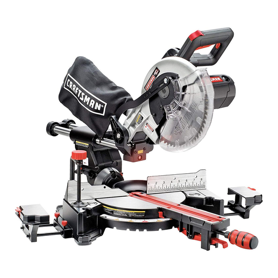
Operator's Manual
2.5 HP (Max. Developed)
10" Blade
4800 R.P.M.
COMPOUND MITER SAW
With Laser Trac®
Model 137.212140
CAUTION;
Before using this Miter Saw,
read this manual
and follow
all its Safety
Rules and
Operating
Instructions
!
Customer
Neip Line
t=800=843=t682
e Safety Instructions
e Installation
• Operation
e Maintenance
e Pads List
Sears, Roebuck and Co., Hoffman Estates,. 1L 60179 U.S.A.
Visit our Craftsman website: _w_w, sears.comlcraftsman
Part No.:137212140001
Advertisement
Table of Contents
Troubleshooting

Related Manuals for Craftsman 137.212140


Summary of Contents for Craftsman 137.212140
- Page 1 • Operation all its Safety Rules and e Maintenance Operating Instructions e Pads List Customer Neip Line t=800=843=t682 Sears, Roebuck and Co., Hoffman Estates,. 1L 60179 U.S.A. Visit our Craftsman website: _w_w, sears.comlcraftsman Part No.:137212140001...
- Page 2 SECTION PAGE SECTION PAGE Warranty ..........Know Your Compound Miter Saw ..Product Specifications ......Glossary of Terms ........ - Power ToolSafety o ......Assembly and Adjustments:; _._.,, ..Compound Miter Saw Safety ....Operation .._........Maintenance ..........Electrical Requirements and Safety ..Accessories and Attachments ....
- Page 3 12.ALWAYS WEAR EYE PROTECTION. Any power tool GENERAL SAFETY INSTRUCTIONS can throw foreign objecl_sinto the eyes and BEFORE USING THIS POWER TOOL could cause permanent eye damage. ALWAYS wear Safety Goggias (not Safety is a combinatio_ of common sense, staying ale_ glasses) that comply with ANSI Safety standard Z87.t Everyday eyeglasses and knowing how to use your power tool...
- Page 4 18.MAKE SURE the blade is not contacting the SPECIFIC SAFETY INSTRUCTIONS workpiece before the switch is turned ON THIS COMPOUND MITER SAW 19JMPORTANT: After completing the cut, release the USE ONLY CROSS-CUTTING SAW BLADES. When ..power switch and wait for the blade to stop before using carbide tipped blades, make sure they have a returning the saw to the raised position..
- Page 5 4. FUSES may "blow" or circuit breakers may trip ELECTRICAL REQUIREMENTS - cont'd frequently if: DOUBLE INSULATED a. MOTOR is overloaded - ovedoading can occur if you feed too rapidly or make too many startJstops The power tool is double insulated to provide a double in a shod time.
- Page 6 RECOMMENDED ACCESSORIES Phillips screwdriver Use only sccessories recommended for thismiter saw. Followinstructions that accompany aocessodes_ Use ot improper accessories may cause hazards • The use el any cutting toot e×cept 10 inch saw blades thai meet the requirements under recommended accessories is prohibited. Do not use accessories such as shaper cutters or dude sets.
- Page 7 2., Place the saw on a secure siafionary work surface. UNPACKING YOUR MITER SAW Separate all parts from the packing material. Check each one with the illustration below lo make certain aJl 'To avoid injury from unexpected sta_ing or electrical shock, items are accounted for, before discarding any packing material, do not plug the power cord into a source of power dur}ng...
- Page 8 Lock off button Upper Blade Guard Cutting Head Handte Dust chute Dust Bag Lower Blade Guard Blade Miter Scale Base " Positive Stop Locking Lever i;ler handle Stop lalch Pivot boll Arbor Lock Bevel Scale : Fence i Ex-lension Wing Mounting Hotes...
- Page 9 CRAFTSMAN COMPOUND MITER SAW TERMS STOP LATCH - Locks the miler saw in the lowered position for compact sloraga and ttarLsportation. ARBOR LOCK - Allows the user to keep the btade lmm rotating while tightening or loosening the arbor locking SWITCH HANDLE - The cutting head handle contains bolt during blade replacement or removal.
- Page 10 ASSEMBLY INSTRUCTIONS To avoid injury and damage to the saw, transport or store the miter saw with the cutting head bcked in the down To avoid injury, do not connect this miter saw to the position. Never use the stop latch to hold the cuing head power source until it is completely assembled adjusted, and you have read and understood this...
- Page 11 Fig. F INSTALLING EXTENSION WINGS (FIG, E) To avoid injury or possible damage to the tool, support long:work pieces by installing the extension wings to extend the work support surface. When using extension and stop block on the right side, hold down clamp must also be In right side, Using hold down clamp on the left side during this operation can cause klck-back and serious injury to the...
- Page 12 Fig,H INSTALUNG BLADE (Fig, F, G, H) ADJUSTING FENCE SQUARENESS (Fig. I) 1oInstal! a 10" blade, making sure the rotation arrow on the 1. Loosen lhetour fence tocking boils (1). blade matches the clockwise rotation arrow on the upper 2. Using a square, lay the heel ot the square against the guard, and the blade teeth are pointing downward, blade, and the rule agoinst the fence (2) as shown.
- Page 13 Lower the blade as tar as possible, Fo Adjust Miter Angles: Loosen the lookout (3). Unlock the miter table by turning the miter handie (1) 3. Turn the adjustment bolt (4) out (counterclockwise) to counterclockwise, decrease the cutting depth or in (clockwise) to While holding the positive-stop locking lever (2) down, increase the cutting depth, grasp the miter handle and rotate the miter table l_'t or...
- Page 14 Support the saw on a }evel work surface. Bolt or clamp the saw to its support To avoid injury from an accidental start, make sure the switch is in the OFF position and the plug is not Place the saw in the desired location, either on a work connected to the power source outlet°...
- Page 15 Keep all guards in place, in working order and properly SAFETY INSTRUCTIONS FOR BASIC SAW adjusted OPERATIONS If any part of this miter saw is missing, bent damaged or broken in any way, or any =_lectrica] BEEORE UStNGTHE [_FFER SAW ..
- Page 16 PLAN YOUR WORK workpieee, fence and table that will let the workpiece shift after ff is cut. Use the tight tool, Don't force a too] or attachment Keep the cut off piece free to move sideways after to do a job it was not designed to do, Use a it is cut ell Otherwise, it could get wedged different tool for any workpiece that can't be held against the blade and thrown vioIenw,...
- Page 17 TURNING THE SAW ON (Fig, Q) BODY AND HAND POSITION (FIG P) To reduce the likelihood of accidenta! starting, a thumb Proper positioning of your bedy and hands when activated lock-OFF switch is located on top of the operating the miter saw will make cutting easier and switcll handle, The safety lock-OFF button (1) must be safe_ Never p!ece hands near the cutting area.
- Page 18 MITER CUT (FIG. R) COMPOUND CUT (FIG. T} When a miler cut is required, un}ock the miler table by A compound cut is the combination of a miler and a tuming the miler handle (1) counterclockwise. While bevel cul simullanaausly. holding the miler handle, press down on the positive Loosen 1he bevel lock handle (1] and position the stop locking lever (2).
- Page 19 WORKP|ECE SUPPORT (FIG. V) AUXILARY WOOD FENCE (FIG, W} Long pieces need extra support° The support should When making multiple or repetitive cuts thai result in be placed under the workpiece. Keep your hands out cut-off pieces of one inch or less, it is possible ior the of the "no,-hands"...
- Page 20 CUTTING A DIMENSIONAL 4X4 WITH ONE CUT CUTTING BASE MOLDING (FIG, Z) (Fig. X) Base me)dings and many other moldings can be cut A dlmensiona,' 4x4-in may be cut in hail with one cut on a compOLmdmiter saw, The setup of the saw by attaching an auxilia_ wood fence of 314 inch thick.
- Page 21 CUING CROWN MOLDING (FIG, AA, BB) Your compound miler saw is suited for the difficult task Fig. BB of cutting crown molding, To fit properly, crown molding Settings for standard crown molding lying flat on must be compound-mitered with extreme accuracy. compound miter saw table The two surfaces on a piece of crown molding that fit fiat against the ceiling and wall are at angles that,...
- Page 22 LOWER BLADE GUARD MAINTENANCE Do not use the saw without the lower btade guard° DANGER The lower blade guard is attached to the saw for your Never put lubricants on the blade while it is spinning. protection. Should the lower guard become damaged, do not use the saw until the damaged guard has been replace&...
- Page 23 i ¸¸/ :--::,; ..To avoid injury from accidental starting, always turn switch OFF and unp{ug the too! before moving, replacing the blade or making adjustment.... Consult your Sears service Center if for any reason the motor will not run. TROUBLESHOOTING GUIDE - MOTOR PROBLEM...
- Page 24 10" MITER SAW PARTS LIST MODEL: 137,212140 When servicing use onlyCRAFTSMAN replacement par|so Use of any other parts may create a HAZARD or cause product damage, Any attempt to repair or replace electrical parts on this miter saw may c_eatea HAZARD unIess repair is done by a qua||fled servicetechnician, Repairservice is avai}able at your nearest Sears Service Centers Always order by I.D, Number PARTS LIST FOR SCHEMATIC...
- Page 25 • MODEL; 137.212140 10'_ COMPOUND MITER SAW : SCHEMATIC 4"...
- Page 26 MODEL: 137.212140 10" COMPOUND MITER SAW PARTS LIST FOR SCHEMATIC MOTOR I,D. NO. DESCRIPTION SIZE 0HV5 BALL BEARING 6204LEU HK_]010 0HX9 NEEDLE BEARING A,,14 OJEB C-RING OJEG C-RING A.20 0JG7 PARALLEL KEY OJX2 MS=0.B-6 HEX.SOC SETSCREW M5"0.8-30 0K3A CR..RE.PAN HD°TAPPING SCREW&WASHER 0K7G CR, RE,ROUND HD, WASHER SCREW...
- Page 27 MODEL: 137.212140 10" COMPOUND MITER SAW SCHEMATIC MOTOR g"...
- Page 28 Your Home For repair-in your home-of all major brand appliances, lawn and garden equipment, or heating and cooling systems, no matter who made _t, no matter who sold For the replacement parts, accessories and Operator's Manuals that you need to do-it-yourself, For Sears professional installation of home appliances and items like garage door openers and water heaters.
Need help?
Do you have a question about the 137.212140 and is the answer not in the manual?
Questions and answers