Table of Contents
Advertisement
Operator's Manual
15Amp
3 HP (Max. Developed)
12" Blade
4200 R.P.M.
SLIDING COMPOUND
MITER SAW
With Laser
Model 137.212060
CAUTION:
Before using this Sliding Miter Saw,
read this manual and follow
all its Safety Rules and
Operating Instructions
Customer
Help Line
1-800-843-1682
e
e
e
e
e
Sears, Roebuck and Co., Hoffman Estates, IL 60179 U.S.A.
Visit our Craftsman website: www.sears.com/craltsman
Safety Instructions
Installation
Operation
Maintenance
Parts List
Pan No.:137212060001
Advertisement
Table of Contents

Related Manuals for Craftsman 137.212060


Summary of Contents for Craftsman 137.212060
- Page 1 Before using this Sliding Miter Saw, Operation read this manual and follow Maintenance all its Safety Rules and Parts List Operating Instructions Customer Help Line 1-800-843-1682 Sears, Roebuck and Co., Hoffman Estates, IL 60179 U.S.A. Visit our Craftsman website: www.sears.com/craltsman Pan No.:137212060001...
- Page 2 SECTION PAGE SECTION PAGE Warranty ........Know Your Sliding Miter Saw ....Product Specifications ....... Glossary of Terms ......Power Tool Safety ......Assembly ........Compound Miter Saw Safety ....Adjustments ........Electrical Requirements and Safety ..Operation ........Accessories and Attachments Maintenance ........
- Page 3 GENERAL SAFETY INSTRUCTIONS 13.WEAR A FACE MASK OR DUST MASK. Sawing BEFORE USING THE SLIDING MITER SAW operation produces dust. 14.SECURE WORK. Use clamps or avise to hold work when practical. It's safer t_an using your hand and it Safety is a combination of commonsense, staying alert frees both hands to operate tool.
- Page 4 SPECIFIC SAFETY INSTRUCTIONS 18. NEVER reach around the saw blade. THIS SLIDING MITER SAW 19.MAKE SURE the blade is not contacting the workpiece before the switch is turned ON. The right side sliding fence must be removed when 20.IMPORTANT: After completing the cut, release the making any right bevel angle cuts greater than 35 °...
- Page 5 DOUBLE INSULATED 4. FUSES may "blow" or circuit breakers may trip The power tool is double insulated to provide a double frequently if: thickness of insulation between you and tool's electrical a. MOTOR is overloaded - overloading can occur if system.
- Page 6 RECOM MENDED ACCESSORIES • Use only accessories recommended for this miter saw. Follow instructions that accompany accessories. of improper accessories may cause hazards. • The use of any cutting tool except 12 inch saw blades that meet the requirements under recommended accessories is prohibited.
- Page 7 Separate all parts from the packing material. Check UNPACKING YOUR SLIDING MITER SAW each one with the illustration to make certain all items are accounted for, before discarding any To avoid injury from unexpected starting or electrical packing material. shock, do not plug the power cord into a source of power during unpacking and assembly.
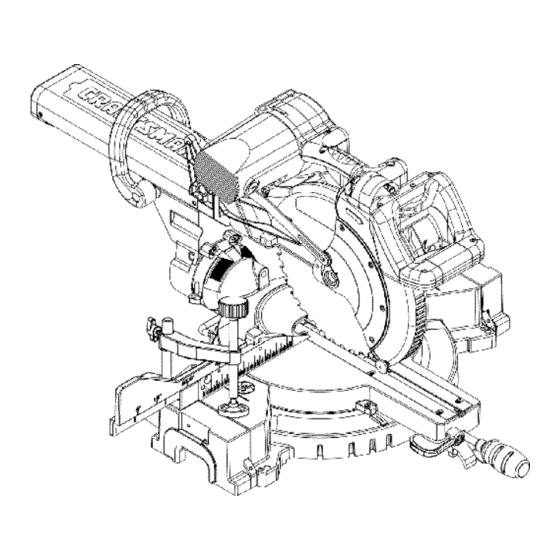
- Page 8 Carry Handle Upper Blade Guard Handle Locking Lever Motor Cutting Head Handle Saw Blade ON / OFF Trigger Switch Bevel Scale Lower Blade Guard Hold Down Clamp Sliding Fence Base Miter Lock Handle Left Extension Table Bevel Lock Handle Turntable Mounting Holes Slide Carriage Slide Carriage...
- Page 9 CRAFTSMAN SLIDING COMPOUND MITER SWITCH HANDLE - The cutting head handle contains the SAW TERMS 1rigger switch and a safety lock-off slide switch. The blade is lowered into the workpiece by pushing down on the ARBOR LOCK - Allows the user to keep the blade from handle.
- Page 10 ASSEM BLY INSTRUCTIONS Fig. B To avoid injury, do not connect this miter saw to the power source until it is completely assembled and adjusted, and you have read and understood this Operators Manual. UNLOCKING THE SLIDE CARRIAGE (Fig, A) Afl_r removing the saw from the carton, loosen the slide carriage lock knob.
- Page 11 POWER CORD BRACKETS (Fig. E) • Do not start the sliding compound miter saw For convenience and to prevent damage to the power without checking for interference between the cord when the miter saw is not in use or is in blade and table insert.
- Page 12 5. Rotate the cover plate (3) to expose the arbor bolt Fig. I (4). Miter saw base 6. Place the blade end wrench over the arbor bolt. Hex head bolt Rubber washer Fig. K Flat washer Workbench Flat washer Lock"washer Hex nut Jam nut NOTE: Mounting hardware is not included with this...
- Page 13 Fig. M BEVEL STOP ADJUSTM ENTS (Fig. N, N-l, N-2, O) NOTE: To ensure accurate cuts, alignment should be checked and adjustments made prior to use. 0 ° Bevel adjustment (Fig N, N-2, O) Loosen bevel lock handle (4- Fig. O) and tilt the cutting arm while pushing in the bevel detent pin (1 - Fig.
- Page 14 Using a combination square, check to see if the detent pin, it may be required to shift the miter saw blade is 33.9 ° to the table. upper arm assembly to the left/right. To adjust, turn the screw in or out with a wrench Loosen the bevel lock handle (4- Fig.
- Page 15 To Square Blade to Fence (Fig. P): While holding the positive stop locking lever up (2), Turn the upper arm assemblyto the 0 ° bevel grasp the miter handle and move the miter table left position and lock in position. or right to the desired angle.
- Page 16 Maximum Cut'dng Depth (Fig. R) The maximum depth trawl of the cutting head was set at the factory, Check to see that the cutting head does not extend more than 1/4" belowthe table insert, and does not touch the control arm throat or any part of the base or table.
- Page 17 SAFETY INSTRUCTIONS FOR BASIC SAW • Keep all guards in place, in working order and proper adjustment. OPERATION If any part of this miter saw is missing, bent damaged or broken in any way, or any electrical parts don't work, BEFORE USING THE MITER SAW turn the saw off and unplug it.
- Page 18 PLAN YOUR WORK • Make sure there are no gaps between the workpiece, fence and table that will let the workpiece shitt during the cut. Use the right tool. Don't force a tool or attachment to do a job itwas not designed to do. Use a different tool •...
- Page 19 BODYAND HAND POSITION (Fig. S) Pull the handle-locking latch (3) to the front of the saw Proper positioning of your body and hands when operating and hold in position. the miter saw will make cutting easier and safer. Never Rotate the handle to the desired positive stop and place hands near the cutting area.
- Page 20 Removing or Installing the Right Sliding Fence If the miter angle desired is NOT one of the ten Removing (Fig. U-l) positive stops noted above, simply lock the table at the Unlockthe fence cam-lockinglever by pushingit out desired angle by pressing down on the quick-cam towardthe rear of the machine.
- Page 21 33.9 ° BEVEL DETENT PIN FOR CROWN MOULDINGS When the cut is complete, release the switch and allow the blade to stop before raising the cutting head (Fig. Y) assembly. NOTE: A bevel detent pin is incorporated into this machine for quick bevel adjustments when the desired bevel angle Fig.
- Page 22 Lower the cutting head so the tip of the blade touches Fig. BB the top surface workpiece at the marked line. While holding the upper arm in position, turn the stop knob (2) until it touches the stop plate (1). Cut two parallel grooves as shown below.
- Page 23 Fig. FF Bladeslot CUTTING CROWN MOLDING (Fig. JJ, KK) The right side sliding fence must be removed when making any right bevel angle cuts greater than 35 ° in combination wi_ any right hand miter angle. This fence must also be removed whenever a 45 ° bevel angle is desired with a miter angle greater than 22.5 °.
- Page 24 Fig. KK Fig. LL 9etii_g_ for standard _row_ mo_dir_g ying f_at on _ompou_d miter saw _ab_e Co¢t_po nd c,l_ c(wl t'_sold Ags Bevel/Miter Settings BEMEL IvlrrlER TYPE OF CUT CHANGING THE BELT (Fig. KK) SETTING SETTING • Unplug your saw. Jnsidecorner-Left side Loosen the bolts (1) and remove the belt cover.
- Page 25 Crown Molding Chart Compound Miter saw Miter and bevel Angle settings Wall to Crown MoldingAngle r',,4_,_dini ..S_,es _ i_w*, Mi!!iii _S!@Ciii,'iM;i :...... 52_8_ Cro!i_'n 1N'Jdin_ ..45,;'45';' Cro,¢,trJ _. ring Bevel Settin g Niter Settitlg Bevel Angle Betweenrvl=terSetirgBevel S etting NiterSetfir@ Be'_@ AngleBetv,_,een Mitet°o...
- Page 26 IVlAINTENANCE LOWER BLADE GUARD DANGER Do not use the saw without the lower blade guard. The Never put lubricants on the blade while it is spinning. lower blade guard is attached to the saw for your protection. Should the lower guard become damaged, do not use the saw until the damaged guard has been To avoid fire or toxic reaction, never use gasoline, replaced.
- Page 27 Toavoid injury f rom accidental starting, always turn theswitch OFF andunplug t hetoolbefore moving, replacing theblade ormaking a djustments. Consult your Sears Service Center if for any reason the motor will not run. TROUBLESHOOTING GUIDE- MOTOR PROBLEM PROBLEM CAUSE SUGGESTED CORRECTIVE ACTION Brake does not...
- Page 28 CRAFTSMAN COM PC UN D MITRE SAW MODEL : 137.212060 When servicing use only CRAFTSMAN replacement parts, Use of any other parts may create a HAZARD or cause product damage. Any attempt to repair or replace electrical parts on this Table Saw may create a HAZARD unless repair is done by a qualified service technician.
- Page 29 CRAFTSMAN COMPOUND MITRE SAW MODEL : 137.212060 SCHEMATIC A...
- Page 30 MODEL : 137.212060 CRAFTSMAN COMPOUND MITRE PARTS LIST FOR SCHEMATIC B Size I.D. No. Description I.D. No, Description Size 2594 MOTOR ASS'Y OKC6 CR. RE.TRUSS HD, TAPPING SCREW M4x6-12 2751 MOTOR LABEL OKD4 CR. RE. PAN HD. SCREW M&xl.O-lO 2752...
- Page 31 Di<?i L_ 7...
- Page 32 CRAFTSMAN COMPOUND MITRE SAW MODEL :137.212060 PARTS LIST FOR MOTOR I.D. No, Descdplion Size OHUT BALL BEARING 6203LLB OHVU BALL BEARING 62COZZ OJ70 FLAT WAS HER ]/4:43/4-7/64 WAVE WASHER BWW62_J OJPD HEX. HD. BOLT M6xl.0q OJX3 HEX. SOC. SF SCREW M5"xO.8_...
- Page 33 "11 I"1'1...
Need help?
Do you have a question about the 137.212060 and is the answer not in the manual?
Questions and answers