Table of Contents
Advertisement
Operator's Manual
®
15 AMP 3 HP (Max. Developed)
10" Blade
4800 R.P.M.
LASER COMPOUND
MITER SAW
With Retractable Laser Trac® System
Model No.
137.212540
CAUTION:
Before using this Miter Saw,
read this manual and follow
all its Safety Rules and
Operating Instructions
•
Safety Instructions
•
Installation
•
Operation
•
Maintenance
•
Parts List
Customer
Help Line
1-800-843-1682
Sears, Roebuck and Co., Hoffman Estates, IL 60179 U.S.A.
Visit our Craftsman website: www.sears.com/craftsman
Part No.:137212540001
Advertisement
Table of Contents

Related Manuals for Craftsman 137.212540


Summary of Contents for Craftsman 137.212540
- Page 1 Installation read this manual and follow • Operation all its Safety Rules and • Maintenance Operating Instructions • Parts List Customer Help Line 1-800-843-1682 Sears, Roebuck and Co., Hoffman Estates, IL 60179 U.S.A. Visit our Craftsman website: www.sears.com/craftsman Part No.:137212540001...
- Page 2 SECTION PAGE SECTION PAGE Warranty ........Know Your Compound Miter Saw ..Product Specifications ....... Glossary of Terms ......Power Tool Safety ......Assembly and Adjustments ....Compound Miter Saw Safety ....Operation ........Electrical Requirements and Safety ..Changing Laser Batteries ....Accessories and Attachments ....
- Page 3 12.ALWAYS WEAR EYE PROTECTION. Any power tool GENERAL SAFETY INSTRUCTIONS can throw foreign objects into the eyes and BEFORE USING THIS POWER TOOL could cause permanent eye damage. ALWAYS wear Safety Goggles (not Safety is a combination of common sense, staying alert glasses) that comply with ANSI Safety and knowing how to use your power tool.
- Page 4 18.MAKE SURE the blade is not contacting the workpiece SPECIFIC SAFETY INSTRUCTIONS FOR THIS before the switch is turned ON. COMPOUND MITER SAW 19.IMPORTANT: After completing the cut, release the 1. USE ONLY CROSS-CUTTING SAW BLADES. When power switch and wait for the blade to stop before using carbide tipped blades, make sure they have a returning the saw to the raised position.
- Page 5 4. FUSES may "blow" or circuit breakers may trip ELECTRICAL REQUIREMENTS - cont'd frequently if: DOUBLE INSULATED a. MOTOR is overloaded - overloading can occur if The power tool is double insulated to provide a double you feed too rapidly or make too many start/stops in a short time.
- Page 6 RECOMMENDED ACCESSORIES Phillips screwdriver • Use only accessories recommended for this miter saw. Follow instructions that accompany accessories. Use of improper accessories may cause hazards. • The use of any cutting tool except 10 inch saw blades that meet the requirements under recommended accessories is prohibited.
- Page 7 Place the saw on a secure stationary work UNPACKING YOUR MITER SAW surface. Separate all parts from the packing material. Check each one with the illustration below to make To avoid injury from unexpected starting or electrical shock, certain all items are accounted for, before do not plug the power cord into a source of power during discarding any packing material.
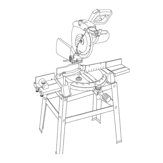
- Page 8 Safety Lock-OFF Button Handle Locking Lever Carrying Handle Cutting Head Handle ON / OFF Switch Blade Wrench Storage Laser Trac g_ Motor Carbide Blade Table Pivot Bolt Lock-Nut Table Insert Bevel Scale Extension Table Mounting Positive Detent Holes Miter Scale Base Laser Trac guide Locking Laser Trac guide lever...
- Page 9 CRAFTSMAN COMPOUND MITER SAW TERMS STOP LATCH - Locks the miter saw in the lowered position for compact storage and transportation. ARBOR LOCK - Allows the user to keep the blade from rotating while tightening or loosening the arbor locking SWITCH HANDLE - The cutting head handle contains bolt during blade replacement or removal.
- Page 10 ASSEMBLE MITER SAW TO STAND ASSEMBLY INSTRUCTIONS 1.Carefully place the miter saw on top of stand. 2.Line up the three mounting holes in the saw base to the stand. To avoid injury, do not connect this miter saw to the power source until it is completely assembled 3.
- Page 11 ASSEMBLY INSTRUCTIONS Fig. C To avoid injury, do not connect this miter saw to the power source until it is completely assembled adjusted, and you have read and understood this Operator's Manual. INSTALLING THE MITER HANDLE (Fig. A) 1. Thread the miter handle (1)into the hole (2)located at the front of the miter table.
- Page 12 INSTALLING THE TABLE EXTENSION (Fig. F) Fig. G To avoid injury or possible damage to the tool, support long work pieces by installing the extension table to extend the work support surface. When using extension and stop block on the right side, hold clown clamp must also be in right side.
- Page 13 REMOVING - cont'd INSTALLING THE HOLD-DOWN CLAMP (Fig. J) 9. Remove t hearborboltandwasher ( 4),theouterblade collar (6),andtheblade (7).Donotremove theinner When using the stop block on the extension table, bladecollar. ( Fig.I) place the hold clown clamp on the same side. Using the NOTE: P ayattention t othepieces removed, noting their clamp on the opposite side can cause kick-back and position anddirection t heyface.Wipethebladecollars...
- Page 14 MITER SCALE (Fig.L) ADJUSTING AUXILIARY FENCES (Fig. M) Themiter sawtablehasnineofthemostcommon 1. First make sure the miter saw fence is square to the a ngle settings with positive stops at 0°, 15°, 22.5 °, 31.6° and blade (see Adjustments Fig. K) and adjust if necessary. 45 °.
- Page 15 CUTTING HEAD DOWNWARD TRAVEL BEVEL STOP ADJUSTMENT (Fig. Q & R) ADJUSTMENT (Fig. P) Before each cutting operation, check the position of the Before each cutting operation, check the position of the blade to make sure it does not contact any metal surface, blade to make sure it does not contact any metal surface.
- Page 16 BEVEL STOP ADJUSTMENT (Fig. Q & R) - Cont'd Parallel Laser Beam Adjustment (Fig. S) 90 ° Bevel indicator (Fig. R) Lower the cutting head so the blade is flush with the side When the blade is exactly g0 ° to the table, loosen the of the scribed line.
- Page 17 SAFETY INSTRUCTIONS FOR BASIC SAW Keep all guards in place, in working order and proper adjustment. OPERATION If any part of this miter saw is missing, bent damaged or broken in any way, or any electrical BEFORE USING THE MITER SAW parts don't work, turn the saw off and unplug it.
- Page 18 PLAN YOUR WORK • Make sure there are no gaps between the workpiece, fence and table that will let the workpiece shift Use the right tool. Don't force a tool or attachment to during the cut. do a job it was not designed to do. Use a different •...
- Page 19 BODY ANDHAND POSITION ( Fig.V) Lock the laser guide assembly into place by pushing Proper p ositioning ofyourbodyandhands when the locking lever to the right side of the saw. operating t hemiter sawwillmake cutting To turn the laser ON or OFF, press the rocker switch easier and safer.
- Page 20 SLIDING FENCE (Fig. Y) BEVEL CUT (Fig. Z-l) The sliding fence must be fully extended to the left The sliding fence must be fully extended to the left when making any compound or bevel cuts. Failure when making any compound cuts. Failure to fully to fully extend the sliding fence will not allow enough extend the sliding fence will not allow enough space...
- Page 21 CUTTING BOWED MATERIAL (Fig. BB) A bowed workpiece must be positioned against the fence When making multiple or repetitive cuts that result in before cutting. Do not position workpiece incorrectly or cut-off pieces of one inch or less, it is possible for the try to cut the workpiece without the support of the fence.
- Page 22 CUTTING A DIMENSIONAL 4X4 WITH ONE CUT CUTTING BASE MOLDING (Fig. GG) (Fig. EE) Base moldings and many other moldings can be cut on a A dimensional 4x4 may be cut in half with one cut by compound miter saw. The setup of the saw depends on attaching an auxiliary wood fence of 3/4 inch thick board.
- Page 23 CUTTING C ROWN MOULDING (Fig. HH, II) Settings for standard crown molding lying flat on Your compound miter saw is suited for the difficult task of compound miter saw table. cutting crown molding. To fit properly, crown molding must be compound-mitered with extreme accuracy. The two surfaces on a piece of crown molding that fit flat Fig.
- Page 24 LOWER BLADE GUARD MAINTENANCE Do not use the saw without the lower blade guard. The DANGER lower blade guard is attached to the saw for your Neverputlubrican_onthebladewhileitisspinning. protection. Should the lower guard become damaged, do not use the saw until the damaged guard has been replaced.
- Page 25 Toavoidinjury fromaccidental starting, always turntheswitch OFFandunplug thetoolbefore moving, replacing t he blade or making a djustments. Consult yourSears Service Center i fforanyreason themotor w illnotrun. TROUBLESHOOTING GUIDE - MOTOR PROBLEM PROBLEM CAUSE SUGGESTED CORRECTIVE ACTION Brake does not 1. Motor brushes not 1.
- Page 26 MITER SAW PARTS LIST MODEL: 137.212540 When servicing use only CRAFTSMAN replacement parts. Use of any other parts may create a HAZARD or cause product damage. Any attempt to repair or replace electrical parts on this miter saw may create a HAZARD unless repair is done by a qualified service technician.
- Page 27 r'rl {"} 228! I1"1 O_QT 2(}8_ I1"1 ¢,€...
- Page 28 10" COMPOUND MITER SAW MODEL: 137.212540 PARTS LIST FOR SCHEMATIC B Size I.D. Description I.D. Description Size 2145 LOCK HANDLE ASS'Y COLOR 0gEM C-RING A-34 2146 LASER ASS'Y 0JET E-RING 0JFB SELF-LOCKING RING SPN-5 2794 TRADE-MARK LABEL 0831 SHAFT SLEEVE COLOR 0JMQ O-RING...
- Page 29 ¢'} O_tv5 24}t5 25!Z OKTZ 0833 ',,,i 0D74...
- Page 30 10" COMPOUND MITER SAW MODEL: 137.212540 PARTS LIST FOR SCHEMATIC MOTOR I.D. Description Size 1100 GEAR BOX COVER 1101 UPPER ARM 1102 SPRING cp4-36 0HX9 NEEDLE BEARING HK-1010 0JX2 HEX.-SOC SET SCREW M5xO.8-6 0K56 CR. RE. COUNT HD. SCREW M5x0.8-12 OKCM CR.-RE.PAN HD, AP, SCREW...
- Page 32 10" COMPOUND MITER SAW MODEL: 137.212540 PARTS LIST FOR SCHEMATIC STAND I.D. SJze Description 093B RUBBER FOOT color 0J4F FLAT WASHER cp8x ] 6-2.5 0KRR SERRATED TOOTHED HEXAGON FLANGE M8x] .25 T=7.5 OSTZ TRADE-MARK LABEL OZlG HD. SQ.NECK BOLT M8x ] .25-12 22XS LONG UPPER SUPPORT...
- Page 33 10" COMPOUN D MITER SAW MODEL: 137.212540 SCHEMATIC STAND .._fA9 ....OJ4[ 22XS OZl (; 22XX 22XY 093B ;}fffffffffffffffffffffffffffffffffffffffffffffffffffffffffffffffffffffffffffffff...
- Page 34 Your Home For repair - in your home - of all major brand appliances, lawn and garden equipment, or heating and cooling systems, no matter who made it, no matter who sold it! For the replacement parts, accessories Operator's Manuals that you need to do-it-yourself. For Sears professional installation of home appliances and items like garage door openers and water heaters.
Need help?
Do you have a question about the 137.212540 and is the answer not in the manual?
Questions and answers