Advertisement
Available languages
Available languages
Quick Links
Operators
Manual
CRItFTSMI:INi
10 IN. SINGLE
BEVEL COMPOUND
MITER SAW
MODEL
NO. 126.32561
CAUTION:
Before using this Miter Saw,
read this manual and follow
all its Safety Rules and
Operating Instructions.
• Safety Instructions
• Installation
• Operation
• Maintenance
• Troubleshooting
• Parts List
• Espa_ol
Sears Brands Management Corporation, Hoffman Estates, IL 60179 U.S.A.
Visit our Craftsman website: www.craftsman.com
Part No: 3848229
Advertisement

Related Manuals for Craftsman 126.32561


Summary of Contents for Craftsman 126.32561
- Page 1 • Operation • Maintenance all its Safety Rules and Operating Instructions. • Troubleshooting • Parts List • Espa_ol Sears Brands Management Corporation, Hoffman Estates, IL 60179 U.S.A. Visit our Craftsman website: www.craftsman.com Part No: 3848229...
- Page 2 A defective product will receive free or replacement if repair is unavailable. For warranty coverage details to obtain free repair or replacement, visit the web site: www.craftsman.com This warranty does not cover the blade which is an expendable part that can wear out from normal use within the warranty period.
- Page 3 MOTOR Power Source ....................120V, 60Hz, 13A Speed ......................4800RPM (No Load) Brake ..........................Electric Double Insulated ........................BLADE SIZE Diameter ..........................10 in. Arbor size .......................... 5/8 in. Blade Type ................. 40T TCT (Tungsten Carbide Tipped) ROTATING TABLE Diameter ........................11-3/4 in.
- Page 4 WARNING ICONS Your power tool and its Operator's Manual may contain "WARNING ICONS" (a picture symbol intended to alert you to, and / or instruct you how to avoid a potentially hazardous condition). Understanding these symbols will help you operate your tool better and safer. Shown below are some of the symbols you may see: SAFETY ALERT: Precautions that involve your safety.
- Page 5 GENERAL SAFETY INSTRUCTIONS 7. MAKE WORKSHOP CHILD PROOF BEFORE USING THIS POWER TOOL with padlocks, master switches or by removing starter keys. Safety is a combination of common sense, 8. DO NOT FORCE THE TOOL. staying alert and knowing how to use your power tool.
- Page 6 19. CHECK FOR DAMAGED PARTS. ALWAYS wear Safety Goggles (not glasses) that comply with Before further use of the tool, a guard or ANSI Safety standard Z87.1. other part that is damaged should be carefully Everyday eyeglasses have only impact checked to determine that it will operate resistant lenses.
- Page 7 SPECIFIC SAFETY INSTRUCTIONS 10. BE SURE both the blade and the collar FOR THIS SINGLE BEVEL COMPOUND are clean and the arbor bolt is tightened MITER SAW securely. 1. DO NOT USE THIN KERF BLADES 11. USE only blade collars specified for your they can deflect and contact guard and can saw.
- Page 8 21. USE THIS COMPOUND MITER SAW 26. SHUT OFF the power before servicing or ONLY FOR Wood and wood based materials. adjusting the tool. DO NOT use it to cut Stainless Steel, Steel, Masonry or Asbestos-based materials. 27. DISCONNECT the saw from the power source and clean the machine when cutting is finished.
- Page 9 To reduce the risk of electrical shock, this WARNING saw has a polarized plug (one blade is wider POWER SUPPLY AND MOTOR than the other). This plug will fit in a polarized SPECIFICATIONS outlet only one way. If the plug does not fit The AC motor used in this saw is a universal, fully in the outlet, reverse plug.
- Page 10 The table below shows the correct size to If the blade is free, try to start the saw again. If the motor still does not start, refer to the use depending on cord length and nameplate TROUBLESHOOTING GUIDE. ampere rating. If in doubt use the next heavier gauge.
- Page 11 Do not use if any damage is suspected. Failure to heed safety ACCESSORIES instructions and warnings can result Visit your Sears Hardware Department or see in serious bodily injury. the Craftsman Power and Hand Tool Catalogue to purchase available accessories for this power tool.
- Page 12 SUPPLIED NOT SUPPLIED Adjustable Wrench Phillips Screwdriver Allen Key (Blade Change) Slotted Screwdriver Allen Key (Adjustments) ,I,1,t,t,I,I,1,1_1 Combination Square (Known to be accurate)
- Page 13 UNPACKING YOUR MITER SAW WARNING If any part is missing or damaged do WARNING not attempt to assemble the miter To avoid injury from unexpected starting saw, or plug in the power cord until or electrical shock, do not plug the the missing or damaged part is power cord into a source of power during correctly replaced.
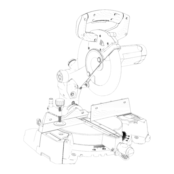
- Page 14 LINE DIAGRAM OF MITER SAW LEFT SIDE VIEW 1- UPPER BLADE GUARD 2 - AUXILIARY BLADE GUARD 3 - CUTTING HEAD HANDLE 4 - BLADE (housed inside a metallic bower blade guard) 5 - FENCE 6 - BEVEL LOCK HANDLE 7 - HOLD DOWN CLAMP 8 - SATELLITE WORKPIECE STAND...
- Page 15 LINE DIAGRAM OF MITER SAW RIGHT SIDE VIEW 1 - LOWER BLADE GUARD 2 - TABLE 3 - CUTTING HEAD LATCHING PIN 4 - ON/OFF TRIGGER SWITCH 5 - MOUNTING HOLE (there are 4 mounting holes in total, 2 at the back and 2 at the front) 6 - ADJUSTABLE STOP PLATE / EXTENSION ARM 7 - ARBOR LOCK BUTTON...
- Page 16 CUTTING H EAD LATCHING PIN - Locks AMPERAGE (AMPS) - Ameasure oftheflow ofelectric current. Higher ratings g enerally themiter s awinthelowered position for means thetoot i ssuited f orheavier use. compact storage and transportation. ARBOR - Theshaft onwhich t heblade is DOUBLE- INSULATED - A form ofelectrical mounted.
- Page 17 GUARD - Protective device that forms a ON/OFF TRIGGER SWITCH - To start the barrier between an hazardous object such as tool, squeeze the trigger. Release the trigger to turn the miter saw OFF. a blade, wheel or cutter and the operator. HOLD DOWN CLAMP - Secures the REVOLUTIONS PER MINUTE (RPM) -...
- Page 18 Locking the Cutting Head in the Down WARNING Position (Fig. B) To avoid injury from unexpected starting or electrical shock, do not plug the power cord into a power source during When not using, transporting or storing the unpacking or assembly. The power cord miter saw, lock the Cutting Head in the down must remain unplugged whenever you are position with the Latching Pin fully engaged...
- Page 19 INSTALLING OR REMOVING A BLADE CAUTION Dispose of the contents of the dust WARNING collection bag in an environmentally Only use blades which are specified responsible way. It may be neccesary to for use with this machine. Ensure that wear a dust mask when emptying the dust the maximum speed of the blade is collection bag.
- Page 20 NOTE: The arbor screw is reversed threaded. 3. Rotate the lower guard up and into the upper blade guard to gain access to the Turn to the right to loosen and to the left to tighten. machine arbor. (Fig. E) 6.
- Page 21 1. Tighten the miter and bevel locks. _, WARNING See OPERATION section. Ensure that the blade collars are clean and 2. To avoid injury from flying dust, position correctly positioned on the arbor. the saw so that other people or bystanders Lower the blade into the table and check for cannot stand too close (or behind) it.
- Page 22 ADJUSTMENT INSTRUCTIONS 2. Place a combination square on the miter table with the rule against the table and the WARNING heel of the square against the blade. (Fig. L) To avoid injury from electric shock or from an accidental start, make sure the switch is in the OFF position and the plug is not connected a power source outlet.
- Page 23 450 Bevel Stop Adjustment NOTE: Ensure that the 33.90 Crown Molding Pin is in its disengaged (outer) position. 1. Loosen the Bevel Lock Handle and tilt the Cutting Head completely to the left until it rests against the 450 stop. 2.
- Page 24 33.9 o Bevel Adjustment If necessary the 33.9 osettings can be checked and adjusted. An angle gauge will be required and this must be accurately set to 33.90 . To engage the Crown Molding Pin: 1. Pull the pin out slightly and rotate 1Aof a turn in either direction (Fig.
- Page 25 CUTTING HEAD TRAVEL 2. If adjustment is necessary, loosen the four (4) Fence adjustment screws using an Allen Key. (Adjustment allen key, supplied) Cutting Head Downward Travel 3. Re-position the Fence in its elongated Adjustment (Fig. S) slots until alignment is achieved. 4.
- Page 26 SAFETY INSTRUCTIONS FOR BASIC SAW downwards at the front of the saw. OPERATION Tighten the arbor bolt. Check for damaged parts. Check for: BEFORE USING THE MITER SAW Cracks in the blade, and for broken, chipped or missing blade teeth. WARNING Alignment of moving parts.
- Page 27 AVAILABLE ACCESSORIES application and limitations as well as the specific potential hazards peculiar to Consult the ACCESSORIES this toot. To avoid injury from accidental ATTACHMENTS section of this contact with moving parts, do not do Operator's Manual for the available layout, assembly or setup work on the accessories.
- Page 28 Do not wear loose clothing, gloves, down clamp to the table. The table should be clean and free from neckties or jewelry (rings, watches etc). They can get caught and draw you into sawdust etc. before the workpiece is moving parts. clamped into position.
- Page 29 BASIC SAW OPERATIONS WARNING WARNING Do not allow familiarity from frequent use of your miter saw to result in a careless For your convenience, your saw has a mistake. A careless fraction of a second is blade brake. The blade brake is not a enough to cause a severe injury.
- Page 30 To turn the LASER 'Off' slide the switch LOWER BLADE GUARD (Fig. V) towards the 'O' position. (Fig. W) NOTE: Lower blade guard operation is automatic. The blade guard will deploy and completely cover the blade as the Cutting Head is allowed to rise to its upper position. (Fig.
- Page 31 To replace, simply slide the Satellite Stand ,A WARNING back into the machine base until it snaps securely into place. The use of optical instruments with this ADJUSTABLE STOP PLATE laser could increase the eye risk hazard. Do not attempt to repair or disassemble the laser.
- Page 32 To engage the stop outboard: Slide the spring-loaded release lock forwards. Pull the stop from its stored position upwards and to the right to the outboard position. Slide the release lock backwards to lock the stop into position. (Fig. Z) 1.
- Page 33 To adjust the Extension Arm. Push the release button on the front of the machine base below the stop plate. Slide the Extension Arm from the machine base, and release the button when at the required distance. ADJUSTING THE FENCE The Left Hand upper portion of the Fence is adjustable.
- Page 34 MAKING A BASIC CUT MAKING A BASIC MITER CUT WARNING Any angle from 45 oleft to 45 o right is Ensure that the workpiece is securely available, and a dual protractor scale can be found on the front of the machine base. clamped to the saw table and against the fence and in the required position, before Positive stops are located at 0°,150,...
- Page 35 NOTE: The Bevel Angle Locking screw has a spring loaded lever. This enables the lever to be repositioned on the locking screw. Repositioning may be necessary to allow the screw to be tightened sufficiently to lock the Cutting Head in the required position. (Fig.
- Page 36 To adjust the fence: (Fig. CC Page 33) Proceed to make the cut as previously described. Locate and loosen the fence adjusting CUTTING BOWED MATERIAL screw. Slide the top portion of the fence leftwards. Before cutting any workpiece, check to see if Lower the Cutting Head to check for it is bowed.
- Page 37 IR = Inside Right CUTTING CROWN MOLDING OL = Outside Left OR = Outside Right Your Craftsman Compound Miter Saw is suited for the difficult task of cutting Crown Molding. To fit properly, Crown Molding must be compound mitered with extreme accuracy.
- Page 38 NOTE: The chart below references a compound cut for Crown Molding ONLY WHEN THE ANGLE BETWEEN THE WALLS EQUALS 900 BEVEL MITER TYPE OF CUT SETTING SETTING Inside Corner-Left side 1) Position top of moulding against fence. 33.9 o 31.6 ° Right 2) Miter table set at Right 31.6 °...
- Page 39 when removed from the machine. DANGER Run new brushes without load for To avoid injury, never put lubricants on approximately 5 minutes. This will help the blade while it is spinning. the break-in process. WARNING To avoid fire or toxic reaction, never TOP BRUSH POSITION use gasoline, naphtha, acetone,...
- Page 40 DUST COLLECTION BAG To maintain extraction efficiency empty the Dust Collection Bag when it becomes approximately 2/3 full. Dispose of the contents in an environmentally responsible manner. The bag has a side zip opening. LUBRICATION All motor bearings in this tool are lubricated with a sufficient amount of high grade lubricant for the life of the unit under normal operating conditions.
- Page 41 WARNING To avoid injury from accidental starting, always turn switch OFF and unplug machine before attempting any maintenance or carrying out any adjustments to your miter saw. TROUBLESHOOTING GUIDE - MOTOR PROBLEM PROBLEM CAUSE SUGGESTED CORRECTIVE ACTION 1. Motor brushes not sealed Brake does not stop the blade 1.
- Page 42 TROUBLESHOOTING GUIDE - SAW OPERATION PROBLEM PROBLEM CAUSE SUGGESTED CORRECTIVE ACTION Blade hits the table or table 1. Incorrectly installed blade. 1. Check blade installation. insert. See INSTALLING OR REMOVING A BLADE section. Cutting head wobbles. 1. Loose pivot bolt.. 1.
- Page 44 019-0001 Main Assembly 8.16.11 019-0143 Knob 019-0011 Left side ext ass 8.16.12 019-0144 Screw 019-0012 Right side ext ass 8.16.13 019-0145 Threaded 019-0013 Motor Assembly 8.16.14 019-0113 Screw M4xl0mm 019-0101 neck 019-0146 Sawblade 019-0102 Spring 019-0147 Inner flange 019-0103 Circlip 019-0148 Screw M4xl0mm 019-0104...
- Page 45 019-0169 Screw M6x25mm 52.38 019-0238 Handle (Lower) 52.39 019-0239 Screw ST4.2x16 019-0013 Motor assembly 52.01 019-0194 Screw M4x6mm 52.40 019-0212 Screw M5x14 52.02 019-0195 Left cover 52.41 019-0184 Spring washer 5mm 52.03 019-0183 Screw M5x16bb 52.42 019-0185 Washer 5mm 52.04 019-0184 Spring washer 5mm 52.43...
- Page 47 • Mantenimiento todas las normas de seguridad e instrucciones de funcionamiento. • Soluci6n de problemas Sears Brands Management Corporation, Hoffman Estates, IL 60179, EE.UU. Visite el sitio Web de Craftsman: www.craftsman.com N° de pieza: 3848229...
- Page 48 Para obtener informaci6n detallada sobre la cobertura de la garantia para la reparaci6n o sustituci6n gratuitas de un producto, visite el sitio Web: www.craftsman.com Esta garantia no cubre la hoja ya que se trata de una pieza fungible que se puede desgastar durante su uso normal dentro del periodo de garantia.
- Page 49 MOTOR Fuente de atimentacion ..................120V, 60Hz, 13A Vetocidad ....................5000RPM (sin carga) Freno ..........................Electrico Aislamiento dobte ........................TAMANO DE LA HOJA Dia.metro ..........................10" Tamafio det a.rbot........................5/8" Tipo de hoja ..........40 dientes con TCT (puntas de carburo de tungsteno) MESA GIRATORIA Dia.metro ...........................
- Page 50 ICONOS DE ADVERTENCIA En la herramienta electrica o en el Manual del operador correspondiente, puede haber "ICONOS DE ADVERTENCIA" (simbolos para avisarle y/o indicarle cbmo evitar una situacibn potencialmente peligrosa). Comprender estos simbolos le ayudara a utilizar la herramienta mejor y con mas seguridad.
- Page 51 INSTRUCCIONES GENERALES 5. NO UTILICE LA HERRAMIENTA SEGURIDAD ANTES DE UTILIZAR ESTA ENTORNOS PELIGROSOS. No utilice las HERRAMIENTA ELC:CTRICA herramientas etectricas en lugares humedos, ni las exponga a la Iluvia o a la nieve. La seguridad es una combinacion de sentido Mantenga el a.rea de trabajo bien iluminada.
- Page 52 amperaje indicado en la ptaca de identificacion. sujetar la pieza siempre que pueda. Es ma.s En caso de duda, utilice el calibre mayor ma.s seguro que utilizar la mano y las deja las dos proximo. Cuanto menor sea el calibre, mayor manos libres para manejar la herramienta.
- Page 53 20. NUNCA DEJE DESATENDIDA LA HERRAMIENTA EN FUNCIONAMIENTO. PONGA EL INTERRUPTOR EN LA POSICION "APAGADO'. No se aleje nunca dejando una herramienta en funcionamiento hasta que no se haya parado ta hoja por compteto y la herramienta se haya desenchufado de la fuente de atimentacion.
- Page 54 INSTRUCCIONES DE SEGURIDAD 8. MANTENGA LAS RANURAS DE ESPECiFICAS PARA ESTA SIERRA VENTILAClON DEL MOTOR LIMPIAS y sin INGLETADORA COMPUESTA virutas ni polvo. 1. NO UTILICE HOJAS CON UN ANCHO 9. ASEGURESE SIEMPRE de que todos DE CORTE FINO ya que pueden dobtarse y los mangos esten bien apretados antes de cortar, incluso si la mesa est&...
- Page 55 26. CORTE ta fuente de atimentaci6n de 18. ASEGORESE de que la hoja no este en contacto con la pieza de trabajo antes poner energia antes del mantenimiento o det ajuste de la herramienta. et interruptor en la posici6n de ENCENDIDO. 19.
- Page 56 ADVERTENCIA ESPECIFICACIONES DE LA FUENTE DE ALIMENTACION Y DEL MOTOR El motor de CA utilizado en esta sierra es de tipo universal y no reversible. Vease "MOTOR" en la seccion Para reducir et peligro de descargas "ESPEClFICACIONES DEL PRODUCTO" de etectricas, esta sierra tiene una clavija la pa.gina 3.
- Page 57 CABLES CALIBRE MiNIMO DE LOS CABLES PROLONGADORES (AWG) Utilice un cable prolongador adecuado. Asegurese de que et cable prolongador (SOLo CUANDO LA CORRIENTE ES DE VOLTIOS) este en buen estado. Si utitiza un cable AMPERAJE L©NGITUD TOTAL DEL CABLE No MASDE 7.62 15.24 30.48...
- Page 58 ACCESORIOS lesiones corporales. Visite et departamento de ferreteria de Sears o consutte et cat&logo de herramientas etectricas y manuates de Craftsman para adquirir los accesorios disponibtes para esta herramienta etectrica.
- Page 59 PROPORClONADA NO PROPORClONADA Llave inglesa ajustable Destornillador Phillips Llave Allen (cambio de la hoja) Destornillador piano Llave Allen ,I,1,t,t,I,I,1,1_1 (ajustes) Escuadra combinada (conocida pot su precisibn)
- Page 60 DIAGRAMA LINEAL DE UNA VISTA LATERAL IZQUIERDA DE LA SIERRA INGLETADORA 1- PROTECTOR SUPERIOR DE LA HOJA 2 - PROTECTOR AUXILIAR DE LA HOJA 3 - MANGO DEL CABEZAL DE CORTE 4 - HOJA (ALOJADA DENTRO DE UN PROTECTOR METALICO INFERIOR DE LA HOJA) 5- GUiA...
- Page 61 DIAGRAMA LINEAL DE UNA VISTA LATERAL DERECHA DE LA SIERRA INGLETADORA 1 - PROTECTOR INFERIOR DE LA HOJA 2 - MESA 3 - PASADOR DE BLOQUEO DEL CABEZAL DE CORTE 4 - INTERRUPTOR DE GATILLO DE ENCENDIDO/APAGADO 5 - ORIFICIO DE MONTAJE (HAY 40RIFIClOS DE MONTAJE EN TOTAL, 2 EN LA PARTE POSTERIOR Y 2 EN LA PARTE FRONTAL)
- Page 62 DESEMBALAJE DE LA SIERRA ADVERTENCIA I INGLETADORA Si faltara alguna pieza o si estuviera daSada, no intente montar la sierra ADVERTENCIA ingletadora ni enchufar el cable de Para evitar lesiones por una puesta en alimentacibn hasta que la pieza que marcha inesperada o por descargas falta o daSada haya sido debidamente etectricas, no enchufe et cable de...
- Page 63 PASADOR DE BLOQUEO AMPERAJE (AMPS) - Una medida det flujo de corriente etectrica. Unos amperajes CABEZAL DE CORTE - BIoquea la sierra ma.s altos normatmente significan que ingletadora en la posicion inferior para un la herramienta es adecuada para una atmacenamiento y transporte compactos.
- Page 64 PROTECTOR - Dispositivo de proteccion ORIFIClOS DE MONTAJE - Se utiNzan para que forma una barrera entre un objeto montar la sierra ingletadora en una superficie petigroso tat como una hoja, disco o cuchilla de trabajo plana y estabte. INTERRUPTOR DE GATILLO DE y et operador.
- Page 65 ADVERTENCIA Para evitar lesiones por una puesta en marcha inesperada o por descargas eldctricas, no enchufe el cable de alimentacibn a ninguna fuente de alimentacibn ni durante el desembalaje ni durante el montaje. El cable de alimentacibn debe permanecer desenchufado siempre que se realicen (Fig.
- Page 66 INSTALACION DE LA BOLSA DE 4. Ajuste la prensa con et tornitlo de RECOGIDA DE POLVO madposa y et volante de mano de modo ta Acopte la bolsa de recogida de potvo en pieza de trabajo quede bien fijada a la base et orificio de extraccion de polvo.
- Page 67 4. Pulse el bot6n de bloqueo del &rbol para bloquear el arbol. (Fig. F) (Fig. F) (Fig. D) 5. Con la Ilave Allen proporcionada que hay 3. Gire el protector inferior hacia arriba y guardada en la parte posterior del cuello del h&galo entrar en el protector superior de cabezal de corte, suelte el tornillo del &rbol la hoja para poder acceder al &rbol de la...
- Page 68 MONTAJE DE LA SIERRA INGLETADORA ,_1= ADVERTENCIA t Para reducir et riesgo de lesiones derivadas de un movimiento inesperado de la sierra, pongala en et lugar deseado sobre un banco de trabajo o sobre cuatquier otro soporte adecuado para la ma.quina. La base de la sierra tiene cuatro orificios de montaje a su traves en los cuates pueden introducirse unos pemos correspondientes...
- Page 69 INSTRUCClONES DE AJUSTE otras personas o transeQntes no queden demasiado cerca de ella (o detra.s). l_lk ADVERTENCIA I 3. Ponga la sierra sobre una superficie ptana Para evitar lesiones como consecuencia y firme donde haya mucho espacio para manipular y apoyar debidamente la pieza de de una descarga electrica o de una puesta trabajo.
- Page 70 2. Coloque una escuadra combinada sobre la mesa ingletadora con la regla contra la mesa y el tal6n de la escuadra contra la hoja. (Fig. L) (Fig. M2) 6. Utilice una Ilave Allen para atornillar o desatornillar el tornillo y ajustar la inclinaci6n de la hoja.
- Page 71 Ajuste del tope del bisel a 450 9. Apriete firmemente la contratuerca tornillo de ajuste una vez conseguida la alineaci6n. NOTA: Asegt_rese de que la punta de la moldura de corona de 33.9 oeste en su posici6n desacoplada (exterior). Ajuste del bisel a 33,90 1.
- Page 72 2. En caso de ser necesario un ajuste, afloje los cuatro tornillos de ajuste de la gufa con una Ilave Allen. (Ajuste de Ilave Allen, suministrada) 3. Vuelva a colocar la gufa en sus ranuras alargadas hasta conseguir la alineaci6n. 4.
- Page 73 DESPLAZAMIENTO DEL CABEZAL DE CORTE Ajuste del desplazamiento descendente del cabezal de corte. (Fig. S) Para evitarque la hoja entreen contactocon alguna partede labase metalicade la maquina, puedeajustarseeldesplazamiento descendente del cabezal de corte. Baje elcabezaJde corte y compruebe si la hoja est&en contactocon la base de la m&quina.En caso de que haya que ajustarel desplazamientodescendente del cabezaJ de corte: 1.
- Page 74 INSTRUCCIONES SEGURIDAD PARA INSPECClONE LA SIERRA ANTES DE EL FUNCIONAMIENTO BASICO DE LA CADA USO SIERRA Desconecte la sierra ingletadora. Para ANTES DE UTILIZAR LA SIERRA evitar lesiones como consecuencia INGLETADORA de una puesta en marcha accidental, desenchufe la sierra antes de realizar ADVERTENCIA ] cuatquier ajuste, incluidos la instatacion Para evitar errores que podrian causarle...
- Page 75 correctamente ajustados. Si atguna Con ta sierra desenchufada, empuje et de las piezas de la sierra ingletadora cabezal de corte todo Io que pueda. Gire fattara, estuviera dobtada, dafiada o rota a mano la hoja y compruebe la holgura. de cuatquier manera, o si no funcionaran Incline et cabezal de corte a un _tnguto las piezas electricas APAGUE la sierra y de biset de 450 y repita la prueba.
- Page 76 APAGADO antes de enchufar la No utilice ropa suetta, guantes, corbatas sierra ingtetadora en una fuente de ni alhajas (anillos, retojes, etc.). Pueden atimentaci6n. atascarse y atraerlo hacia las piezas m6viles. Utilice calzado antideslizante. PLANIFIQUE EL TRABAJO Utilice la herramienta adecuada. Si tiene et pelo largo, recojaseto.
- Page 77 EXTREME LAS PRECAUClONES la cara y el cuerpo queden fuera de la linea LAS PIEZAS DE TRABAJO GRANDES de un posibte contragotpe. NUNCA extienda CON UNA FORMA IRREGULAR et brazo o la mano de modo que quede "en linea" con la trayectoria de corte de la hoja. Los cortes a putso son una de las causas Utilice soportes adicionates tales como principates de accidentes y jama.s deben...
- Page 78 POSICION DEL CUERPO Y DE LAS Si la hoja no se detiene en menos de 6 MANOS (Fig. T). segundos despu6s de haber soltado el interruptor de gatillo de ENCENDIDO/ _lk ADVERTENCIA APAGADO, espere a que la hoja se pare, desenchufe la sierra y pbngase en contacto con el Centro de Servicio cerca o dentro de la "zona sin T_cnico de Sears Ilamando al 1-800469-...
- Page 79 PROTECTOR INFERIOR DE LA HOJA posici6n de "Encendido" para que aparezca la linea de I&ser. Para "Encender" el LASER, (Fig. V) Ileve el interruptor de encendido/apagado LASER a la posici6n 'T'. NOTA: El funcionamiento del protector inferior de la hoja es autom&tico. El Para "Apagar"...
- Page 80 soportar adecuadamente piezas de trabajo largas. (Fig. X) _IL ADVERTENCIA ] El uso de instrumentos 6pticos con este (Fig. X) I&ser podrfa aumentar el peligro de riesgo para los ojos. Para meterlo, no tiene m&s que deslizar de No intente reparar ni desmontar el I&ser. nuevo el soporte satelite al interior de la base Deje que todas las reparaciones las de la m&quina hasta que quede fijado de...
- Page 81 COLOCACION PRECISA DE LA PLACA DE Para guardarlo, siga los pasos anteriores TOPE pero a la inversa. Fije la placa de tope en la posici6n interior o exterior tal y como se ha indicado arriba. Pulse el bot6n de liberaci6n que se encuentra en la parte delantera de la base de la m&quina debajo de la placa de tope.
- Page 82 BRAZO DE EXTENSION NOTA: La porci6n superior deslizante de la guia es "cautiva" y no puede extraerse por Con la placa de tope en la posici6n completo de la guia. guardada, el brazo de extensi6n puede utilizarse para soportar piezas de trabajo Para el ajuste: largas (Fig.
- Page 83 REALIZACION DE UN CORTE BASICO cierre siempre el taller cuando se estd utilizando. Guarde la herramienta en un ADVERTENCIA armario seguro y cerrado con Ilave o similar Asegdrese de que la pieza de trabajo estd donde no puedan acceder los usuarios no cualificados ni los niSos.
- Page 84 NOTA: El tornillo de bloqueo del &ngulo de bisel tiene una palanca con carga de resorte. Esto permite la reposici6n de la palanca sobre el tornillo de bloqueo. La reposici6n puede ser necesaria para poder apretar el tornillo Io suficiente para bloquear el cabezal de corte en la posici6n requerida.
- Page 85 • Destice la porcion superior de la guia hacia la izquierda. • Baje el cabezat de corte para comprobar la holgura. • Apriete et tornitlo de ajuste de la guia. Proceda con la reatizacion del corte segun Io descrito anteriormente en REALIZACION UN CORTE BASlCO.
- Page 86 Outside Corner IL = Interior izquierda CORTE DE LA MOLDURA DE CORONA IR = Interior derecha Su sierra ingletadora compuesta de Craftsman 0L = Exterior izquierda es apta para la dificil tarea de cortar molduras OR = Exterior derecha...
- Page 87 NOTA: La tabla de abajo hacer referencia a un corte compuesto para molduras de corona UNICAMENTE CUANDO EL ANGULO ENTRE LAS PAREDES ES DE 900 CLAVE AJUSTE DEL AJUSTE DEL TIPO DE CORTE BISEL INGLETE Esquina interior-Lado izquierdo 1) Ponga la parte superior de la moldura 31.6 °...
- Page 88 Para evitar lesiones, nunca lubrique la NOTA: Las escobitlas usadas pero utitizabtes hoja mientras gira. se pueden reemptazar pero solo si se introducen en la misma posicion que estaban [_IL ADVERTENCIA 1 cuando se extrajeron de la ma.quina. Para evitar incendios o reacciones t6xicas, nunca utiNce gasoNna, nafta, Ponga en funcionamiento las escobiltas...
- Page 89 PROTECTOR INFERIOR DE LA HOJA ADVERTENCIA 1 No utilice la sierra si el protector inferior de la hoja est& daSado o no funciona correctamente. Si el protector est& daSado o no funciona, hay que reemplazarlo antes de utilizar la sierra. El rendimiento y el funcionamiento seguro de los protectores de repuesto se deben probar con la m&quina desconectada de la...
- Page 90 ADVERTENCIA Para evitar lesiones como consecuencia de una puesta en marcha accidental, APAGUE siempre el interruptor y desenchufe la maquina antes de realizar cualquier tarea de mantenimiento o de realizar cualquier ajuste en la sierra ingletadora. GU|A DE SOLUCION DE PROBLEMAS - MOTOR PROBLEMA CAUSA DEL PROBLEMA MEDIDAS CORRECTIVAS...
- Page 91 GU|A DE SOLUCION DE PROBLEMAS - FUNCIONAMIENTO DE LA SIERRA PROBLEMA CAUSA DEL PROBLEMA MEDIDAS CORRECTIVAS SUGERIDAS La hoja golpea la mesa o el 1. La hoja est& mal instalada.. 1. Compruebe la instalaci6n de la inserto de la mesa. hoja.
- Page 92 Your Home For troubleshooting, product manuals and expert advice: www.managemylife.com For repair - in your home - of all major brand appliances, lawn and garden equipment, or heating and cooling systems, no matter who made it, no matter who sold it! For the replacement parts, accessories owner's manuals that you need to do-it-yourself.
Need help?
Do you have a question about the 126.32561 and is the answer not in the manual?
Questions and answers