Advertisement
Operator's Manual
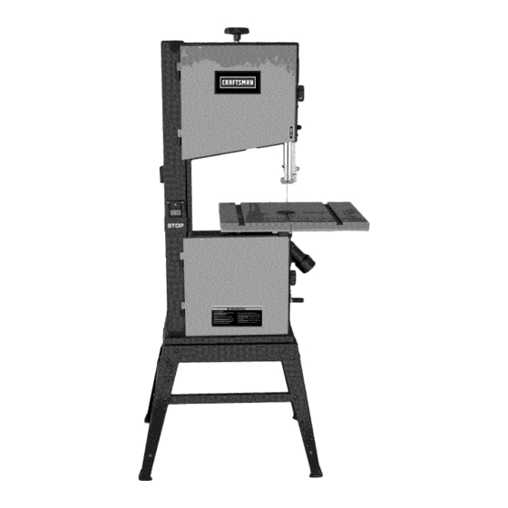
14-in. BAND SAW
1 HP MOTOR
Model 124.32607
CAUTION: Before using this
product, read this manual and
follow all its Safety Rules
and Operating Instructions.
Sears Brands Management Corporation,
Hoffman Estates, IL 60179 U.S.A
WARNING: Some dust created by power sanding, sawing, grinding, drilling, and other construction activities contains
chemicals known to the State of California to cause cancer and birth defects or other reproductive harm.
Advertencia: Algunos polvo creado al lijar, serrado, rectificado, taladrado, y otras actividades de construcción contiene
sustancias químicas que se sabe que el Estado de California, que causa cáncer y defectos de nacimiento u otros daños
reproductivos.
Safety Instructions
Assembly
Operation
Maintenance
Troubleshooting
Parts List
Espanol (PG. 26)
Advertisement
Table of Contents

Related Manuals for Craftsman 124.32607


Summary of Contents for Craftsman 124.32607
- Page 1 Operator’s Manual 14-in. BAND SAW 1 HP MOTOR Model 124.32607 CAUTION: Before using this Safety Instructions product, read this manual and Assembly follow all its Safety Rules Operation and Operating Instructions. Maintenance Troubleshooting Parts List Espanol (PG. 26) Sears Brands Management Corporation, Hoffman Estates, IL 60179 U.S.A...
-
Page 2: Table Of Contents
For warranty coverage details to obtain free repair or replacement, visit the web site: www. craftsman. com This warranty does not cover the blade, which is an expendable part that can wear out from normal use within the warranty period. -
Page 3: Specifications
Always Wear Proper Apparel. Never wear loose clothing or jewelry that might get caught in moving parts. Rubber-soled footwear is recommended for the best footing. Always Use Safety Glasses and Wear Hearing Protection. Also use a face or dust mask if the cutting operation is dusty. Never Overreach. -
Page 4: Assembly
Hex Nut M6.............2 UNPACKING AND CHECKING CONTENTS Hex Bolt M8x45..........1 Model 124.32607 14” Band Saw is shipped complete in one box. Hex Nut M8.............1 A. Separate all parts from carton and check each item with Carton Contents list below to make sure all items are accounted for, before Wing nut M6.............1... - Page 5 3. INITIAL ASSEMBLY The 124.32607 band saw is supplied partly assembled. Prior to use, the following items have to be assembled: Open Stand, 2-1/2” Dust Port, Table, Blade Tension Knob, Tool Holder, and Crank Handle. WARNING: To avoid injury, do not attempt to run or use this machine until all parts are assembled and working properly.
- Page 6 E. Locate four hex bolts and four lock washers from the bag of loose I. Assemble the tool holder to the column of the band saw with two parts used to mount the table. Mount the table to the upper table pan head screws.
-
Page 7: Getting To Know Your Band Saw
KNOW YOUR BAND SAW Blade Tension Knob Blade Tension Door Locking Knob Indicator Blade Tracking Knob Upper Bandwheel Door Tool Holder Guide Post Adjusting Knob Blade Guides Table Insert Switch Upper Table Trunnion Lower Bandwheel Table Lower Table Trunnion Motor Door 2-1/2”... - Page 8 3. SETTING TABLE SQUARE BACK OF BLADE 6. CHANGING AND ADJUSTING THE SAW BLADE Place a square against the back (non-tooth) side of the saw blade. If This band saw is factory-equipped with a general-purpose wood you find that the table runs up hill or down hill as you feed the cutting blade, the saw blade is set prior to delivery.
- Page 9 8. SETTING THE CUTTING HEIGHT The Lower Blade Guide A. To adjust the lower blade guides, first position the right and left A. The upper blade guide should be set as close as practical against roller guides relative to the blade by loosening the lock nut (FIG. 21) the work piece.
- Page 10 13. DRIVE BELT POSITIONS HIGH/LOW SPEED For the low speed 1620 ft/min, fit the belt to the front pulley on For the high speed 3340 ft/min, the belt should be fitted to the both the motor and bandwheel. (See FIG. 23) rear pulley on both the motor and bandwheel.
-
Page 11: Operation
OPERATION WARNING: Before starting check if any part of your band saw is FIG. 26 Blade missing, malfunctioning, has been damaged or broken, such as the motor switch, or other operation control, a safety device or the power Correct cord, turn the band saw off and unplug it until the particular part is properly repaired or replaced. -
Page 12: Maintenance
MAINTENANCE WARNING: To avoid injury due to unexpected starting, before FIG. 29 cleaning or carrying out maintenance work, switch off and disconnect the band saw from the power source. Never use water or other liquids to clean the band saw. Use a dry brush. -
Page 13: Troubleshooting
Clean the machine regularly. Open the Repair Protection Agreements doors and remove the sawdust with a vacuum cleaner. Congratulations on making a smart purchase. Your new Craftsman ® product is designed and manufactured for years of Sawdust inside the motor housing. This is normal Clean the ventilating slots of the motor with dependable operation. -
Page 14: Parts Diagrams
MFG. PART NO. Front beam 1-JL21050004-001Z Side beam 1-JL21050005-001Z 1-JL21050001-001Z Side panel 1-JL21050003-001Z Front panel 1-JL21050002-001Z Hex nut 1-NUT5/16B Washer 1-WSH8GB97D1B Hex bolt 1-NEC5/16X5/8B Washer 1-WSH6GB96B Hex nut 1-NUT1/4B Hex bolt 1-HEX1/4X1-3/4B Rubber shoe 1-JL40060005 Washer 1-WSH6GB97D1B Craftsman 14-inch Band Saw 124.32607... - Page 15 PARTS DIAGRAM B Craftsman 14-inch Band Saw 124.32607...
- Page 16 1-JL21043001 Lower guide support 1-M6GB889Z Lock nut M6 1-JL21010019 Dust port 2-1/2” Hex bolt 1-M6X12GB70D1Z Adjusting knob cap 1-JL20024001-001S 1-JL20044001-001S Adjusting knob body 1-JL20044002 Tube 1-SR21020003 Ruler 1-JL22040003 Spring washer Gear 1-JL22040001 Power Cord 1-U23162300-551 Craftsman 14-inch Band Saw 124.32607...
- Page 17 PARTS DIAGRAM C Craftsman 14-inch Band Saw 124.32607...
- Page 18 1-CLP17GB894D1B Retaining ring 17 1-M6X20GB5783Z Hex Bolt M6x20 Special Hex Nut 1-JL20020004 Hex Nut M6 1-M6GB6170Z 1-JL21020002B Lower bearing bolt 1-WSH8GB96Z Washer 8 1-M8X16GB70Z Hex Socket set screw M8X16 1-WSH8GB93Z Spring washer Motor Cable 1-U13161200-747 Craftsman 14-inch Band Saw 124.32607...
- Page 19 PARTS DIAGRAM D Craftsman 14-inch Band Saw 124.32607...
- Page 20 1-WSH6GB97D1Z Washer 6 1-M6X45GB70Z Socket head bolt 1-JL21031001D001G Table 1-JL20031002-001S Table insert 1-JL20032001 Upper table trunnion 1-WSH8GB96Z Washer 8 1-M8X50GB14Z Carriage bolt M8x50 1-WSH8GB97D1Z Washer 8 1-JL20010016-001S Wing nut M8 1-M8GB6170Z 1-M8X45GB5783Z Bolt 1-M6X10GB80B Screw Craftsman 14-inch Band Saw 124.32607...
Need help?
Do you have a question about the 124.32607 and is the answer not in the manual?
Questions and answers