
Related Manuals for Gigabyte MSH61DI


Summary of Contents for Gigabyte MSH61DI
- Page 1 MSH61DI LGA1155 socket motherboard for Intel Core i3 / Core ® ™ ™ Core i7 processors/ Intel Pentium series processors ™ ® ® User's Manual Rev. 1001...
- Page 2 GIGABYTE's prior written permission. Documentation Classifications In order to assist in the use of this product, GIGABYTE provides the following types of documentations: For quick set-up of the product, read the Quick Installation Guide included with the product.
-
Page 3: Table Of Contents
Table of Contents Box Contents ........................4 MSH61DI Motherboard Layout ..................5 Chapter 1 Hardware Installation ..................7 Installation Precautions ..................7 1-2 Product Specifications ..................8 Installing the CPU and CPU Cooler ............... 10 1-3-1 Installing the CPU ....................10 1-3-2 Installing the CPU Cooler ..................12 Installing the Memory .................. -
Page 4: Box Contents
Box Contents MSH61DI motherboard Driver CD Two SATA cables I/O Shield • The box contents above are for reference only and the actual items shall depend on the product package you obtain. The box contents are subject to change without notice. -
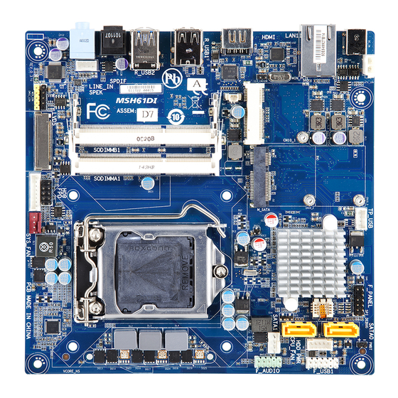
Page 5: Msh61Di Motherboard Layout
MSH61DI Motherboard Layout - 5 -... - Page 6 Item Code Description SPEK Speaker cable connector LINE_IN Audio Line In port SPDIF Optical S/PDIF Out connector R_USB2 USB 3.0 ports R_USB1 USB 2.0 ports Battery connector HDMI HDMI port CLR_CMOSHW Clear CMOS jumper LAN1 RJ45 LAN port DC_IN DC In power connector ATX_19V 2 pin power connector MIN_PCIE1...
-
Page 7: Chapter 1 Hardware Installation
Chapter 1 Hardware Installation Installation Precautions The motherboard contains numerous delicate electronic circuits and components which can become damaged as a result of electrostatic discharge (ESD). Prior to installation, carefully read the user's manual and follow these procedures: • Prior to installation, do not remove or break motherboard S/N (Serial Number) sticker or warranty sticker provided by your dealer. -
Page 8: Product Specifications
1-2 Product Specifications Support for Intel Core i7, Core i5, Core i3 processors/Intel Pentium Š ® ™ ™ ™ ® ® processors in the LGA1155 package Support Up to 95W Š L3 cache varies with CPU Š Chipset Intel H61 Sandy Bridge chipset Š... - Page 9 1 x 64 Mbit flash Š AMI BIOS Š Form Factor Mini ITX Form Factor; 170cm x 170cm Š * GIGABYTE reserves the right to make any changes to the product specifications and product-related information without prior notice. - 9 - Hardware Installation...
-
Page 10: Installing The Cpu And Cpu Cooler
Read the following guidelines before you begin to install the CPU: • Make sure that the motherboard supports the CPU. (Go to GIGABYTE's website for the latest CPU support list.) • Always turn off the computer and unplug the power cord from the power outlet before installing the CPU to prevent hardware damage. - Page 11 B. Follow the steps below to correctly install the CPU into the motherboard CPU socket. Before installing the CPU, make sure to turn off the computer and unplug the power cord from the power outlet power plug to prevent any damage to prevent damage to the CPU. Step 1: Step 2: Gently press the CPU socket lever handle down...
-
Page 12: Installing The Cpu Cooler
1-3-2 Installing the CPU Cooler Follow the steps below to correctly install the CPU cooler on the motherboard. (The following procedure uses Intel boxed cooler as the example cooler.) ® Male Push Direction of the Arrow Sign on The Top the Male Push of Female Push Pin... -
Page 13: Installing The Memory
• Make sure that the motherboard supports the memory. It is recommended that memory of the same capacity, brand, speed, and chips be used. (Go to GIGABYTE's website for the latest supported memory speeds and memory modules.) • Always turn off the computer and unplug the power cord from the power outlet before installing the memory to prevent hardware damage. -
Page 14: Installing A Memory
1-4-2 Installing a Memory Before installing a memory module, make sure to turn off the computer and unplug the power cord from the power outlet to prevent damage to the memory module. Be sure to install DDR3 DIMMs on this motherboard. Installation Step: Step 1. -
Page 15: Back Panel Connectors
Back Panel Connectors DC Power Jack Connect the DC power to this port. RJ-45 LAN Port The Gigabit Ethernet LAN port provides Internet connection at up to 1 Gbps data rate. The following describes the states of the LAN port LEDs. HDMI Port The HDMI (High-Definition Multimedia Interface) provides an all-digital audio/video interface to transmit the uncompressed audio/video signals and is HDCP compliant. - Page 16 Connection/ Speed LED Activity LED Connection/Speed LED: Activity LED: State Description State Description Orange 1 Gbps data rate Blinking Data transmission or receiving is occurring Green 100 Mbps data rate No data transmission or receiving is occurring LAN Port 10 Mbps data rate • When removing the cable connected to a back panel connector, first remove the cable from your device and then remove it from the motherboard.
-
Page 17: Internal Connectors
Internal Connectors F_PANEL SYS_FAN SATA1/2 LVDS HDD_PWR WEB_CON F_USB1 DMIC_CON TV_USB SPEK TP_USB BL_SW F_AUDIO ATX_19V CLR_CMOSHW CPU_FAN Read the following guidelines before connecting external devices: • First make sure your devices are compliant with the connectors you wish to connect. • Before installing the devices, be sure to turn off the devices and your computer. - Page 18 1) F_PANEL (Front Panel Header) Connect the power switch, reset switch, speaker, chassis intrusion switch/sensor and system status indicator on the chassis to this header according to the pin assignments below. Note the positive and negative pins before connecting the cables. 12 11 Pin No.
- Page 19 2) SATA1/2 (SATA 3Gb/s Connectors) The SATA connectors conform to SATA 3Gb/s standard and are compatible with SATA 1.5Gb/s standard. Each SATA connector supports a single SATA device. SATA2 SATA1 Pin No. Definition 3) HDD_PWR (HDD Power Connector) Pin No. Definition +12V Hardware Installation...
- Page 20 4) F_USB1 (USB Headers) The headers conform to USB 2.0/1.1 specification. Each USB header can provide two USB ports via an optional USB bracket. For purchasing the optional USB bracket, please contact the local dealer. Pin No. Definition USB Power 5V USB Power 5V USB D- USB D-...
- Page 21 7) F_AUDIO (Front Panel Audio Header) The front panel audio header supports Intel High Definition audio (HD) and AC'97 audio. You may connect your chassis front panel audio module to this header. Make sure the wire assignments of the module con- nector match the pin assignments of the motherboard header.
- Page 22 9/10) CPU_FAN/SYS_FAN (CPU Fan/System Fan Headers) The motherboard has a 4-pin CPU fan header (CPU_FAN) headers. Most fan headers possess a foolproof insertion design. When connecting a fan cable, be sure to connect it in the correct orientation (the black connector wire is the ground wire). The motherboard supports CPU fan speed control, which requires the use of a CPU fan with fan speed control design.
- Page 23 11) LVDS (LVDS Headers) LVDS stands for Low-voltage differential signaling, which uses high-speed analog circuit techniques to provide multigigabit data transfers on copper interconnects and is a generic interface standard for high-speed data transmission. Pin No. Definition Pin No. Definition +RXO3 -RXO3 VCC3...
- Page 24 12) WEB_CON (WebCAM Headers) Pin No. Definition Power USB D- USB D+ 13) DMIC_CON (DMIC Headers) Pin No. Definition Power DMICDATA DMICCLK Hardware Installation - 24 -...
- Page 25 14) SPEK (Speaker Headers) Pin No. Definition Speaker OUT L- Speaker OUT L+ Speaker OUT R+ Speaker OUT R- 15) BL_SW (Back Light Switch) Pin No. Definition BL_DOWN BL_UP - 25 - Hardware Installation...
- Page 26 16) ATX_19V (2 Pin Power Connector) Pin No. Definition +19V 17) CLR_CMOSHW (Clearing CMOS Jumper) Use this jumper to clear the CMOS values (e.g. date information and BIOS configurations) and reset the CMOS values to factory defaults. To clear the CMOS values, place a jumper cap on the two pins to temporarily short the two pins or use a metal object like a screwdriver to touch the two pins for a few seconds.
-
Page 27: Chapter 2 Bios Setup
Chapter 2 BIOS Setup BIOS (Basic Input and Output System) records hardware parameters of the system in the CMOS on the motherboard. Its major functions include conducting the Power-On Self-Test (POST) during system startup, saving system parameters and loading operating system, etc. BIOS includes a BIOS Setup program that allows the user to modify basic system configuration settings or to activate certain system features. - Page 28 The Functions of the <F11> and <F12> keys (For the Main Menu Only) F11: Save CMOS to BIOS This function allows you to save the current BIOS settings to a profile. You can create up to 8 profiles (Profile 1-8) and name each profile.
-
Page 29: The Main Menu
The Main Menu Once you enter the BIOS Setup program, the Main Menu (as shown below) appears on the screen. Use arrow keys to move among the items and press <Enter> to accept or enter other sub-menu. Main Menu Help The on-screen description of a highlighted setup option is displayed on the bottom line of the Main Menu. - Page 30 BIOS Version Display version number of the BIOS setup utility. BIOS Vendor Display BIOS vendor information. Core Version Display version of the processor. Compliency Display compliency information. Project Version Display version number of the project. BIOS Build Date and Time Displays the date and time when the BIOS setup utility was created.
-
Page 31: Advanced Menu
Advanced Menu The Advanced menu display submenu options for configuring the function of various hardware components. Select a submenu item, then press Enter to access the related submenu screen. Legacy OpROM Support Launch PXE OPROM Enable/Disable Boot Option for PXE device with option ROM. Options available: Enabled/Disabled. -
Page 32: Acpi Settings
2-2-1 ACPI Settings ACPI Settings ACPI Sleep State Select the highest ACPI sleep state the system will enter, when the suspend button is pressed. Suspend Disabled/S1 (CPU Stop Clock)/S3 (Suspend to RAM). Default setting is S3 (Suspend to RAM). BIOS Setup - 32 -... -
Page 33: Cpu Configuration
2-2-2 CPU Configuration CPU Configuration CPU Type Displays the processor type information. CPU Signature Displays the processor ID information. Processor Cores Display the information of the processor core. Intel HT Technology Display Intel Hyper Threading Technology function support information. Intel VT-x Technology Display Intel Virtualization Technology function support information. -
Page 34: Intel Virtualization Technology
Intel Virtualization Technology Select whether to enable the Intel Virtualization Technology function. VT allows a single platform to run multiple operating systems in independent partitions. Options available: Enabled/Disabled. Default setting is Disabled. CPU C3/C6 Support (Note) Allows you to determine whether to let the CPU enter C3/C6 mode in system halt state. When enabled, the CPU core frequency and voltage will be reduced during system halt state to decrease power con- sumption. -
Page 35: Sata Configuration
2-2-3 SATA Configuration SATA Configuration SATA Port 0/SATA Port 1/mSATA The category identifies Serial ATA and mSATA types of hard disk that are installed in the computer. System will automatically detect HDD type. Note that the specifications of your drive must match with the drive table. The hard disk will not work properly if you enter improper information for this category. - Page 36 PIO Mode This feature allows you to set the PIO (Programmed Input/Output) mode for the two IDE devices (Master and Slave drives) attached to that particular IDE channel. Option available: Auto/Disabled. Default setting is Auto. PIO Mode This feature allows you to set the PIO (Programmed Input/Output) mode for the two IDE devices (Master and Slave drives) attached to that particular IDE channel.
-
Page 37: Intel Txt(Lt) Configuration
2-2-4 Intel TXT(LT) Configuration Intel TXT(LT) Configuration The Intel Trusted Execution Technology (TXT) submenu is a display page for the Intel TXT information. Items on this window are non-configurable. - 37 - BIOS Setup... -
Page 38: Usb Configuration
2-2-5 USB Configuration Legacy USB Support Enables or disables support for legacy USB devices. Options available: Auto/Enabled/Disabled. Default setting is Enabled. USB 3.0 Support When enabled, the USB 3.0 controller will function normally. Options available: Enabled/Disabled. Default setting is Enabled. XHCI Hand-off Enable/Disable XHCI Hand-off function. - Page 39 Device reset time-out Define USB device reset start unit command timeout. Options available: 10 sec/20sec/30sec/40sec. Device power-up delay Define USB device powering up start unit command timeout. When this item is set to Manual, you can press numeric keys to configure desired values. Options available: Auto/Manual.
-
Page 40: H/W Monitor
2-2-6 H/W Monitor Press Enter to view the Hardware Monitor screen which displays a real-time record of the CPU/system tem- perature, and fan speed, Items on this window are non-configurable. CPU/SYS SMART FAN Control Enable CPU/System Fan Stop Warning function. Option available: Enabled/Disabled. -
Page 41: Chipset Menu
Chipset Menu VT-d Enable/Disable Intel VD-d Technology function. Options available: Enabled/Disabled. Default setting is Disabled. Iniate Graphic Adapter Select which graphic controller to use as primary boot device. Options available: IGD/PEG/IGD. Default setting is PEG/IGD. IGD Memory Determone the IGD shared memory size. Options available: 32M/64M/96M/128M/160M/192M/224M/256M/288M/320M/352M/384M/416M/448M/ 480M/512M/Disabled. - Page 42 Azalia HD Audio Enable/Disable onboard audio controller. Options available: Enabled/Disabled. Default setting is Enabled. BIOS Setup - 42 -...
-
Page 43: Boot Menu
Boot Menu The Boot menu allows you to set the drive priority during system boot-up. BIOS setup will display an error message if the drive(s) specified is not bootable. Boot Configuration Bootup NumLock State Allows you to select power-on state for NumLock function. Boot Priority Order Options available: On/Off. -
Page 44: Security Menu
Security Menu The Security menu allows you to safeguard and protect the system from unauthorized use by setting up ac- cess passwords. There are two types of passwords that you can set: • Adminstrator Password Entering this password will allow the user to access and change all settings in the Setup Utility. •... -
Page 45: Exit Menu
Exit Menu The Exit menu displays the various options to quit from the BIOS setup. Highlight any of the exit options then press Enter. Save Changes and Exit Saves changes made and close the BIOS setup and exit system setup. Options available: Yes/No. -
Page 46: Restore As User Defaults
Restore as User Defaults Press <Enter> on this item and then press the <Y> key to restore user default settings. Options available: Yes/No. Restore as User Defaults Press <Enter> on this item and then press the <Y> key to restore user default settings. Options available: Yes/No.
Need help?
Do you have a question about the MSH61DI and is the answer not in the manual?
Questions and answers