Table of Contents
Advertisement
Quick Links
Advertisement
Table of Contents

Related Manuals for Gigabyte MUQ77EI


Summary of Contents for Gigabyte MUQ77EI
- Page 1 MUQ77EI Intel Socket uPGA988 processor motherboard ® User's Manual Rev. 1001...
- Page 2 GIGABYTE's prior written permission. Documentation Classifications In order to assist in the use of this product, GIGABYTE provides the following types of documentation: For detailed product information, carefully read the User's Manual.
-
Page 3: Table Of Contents
Table of Contents Box Contents ........................4 MUQ77EI Motherboard Layout ..................5 Chapter 1 Hardware Installation ..................7 Installation Precautions ..................7 1-2 Product Specifications ..................8 Installing the CPU ..................10 Installing the Memory ..................11 1-4-1 Installing a Memory ....................11 Back Panel Connectors .................. 12 Internal Connectors .................. -
Page 4: Box Contents
Box Contents MUQ77EI motherboard Driver CD Two SATA cables I/O Shield • The box contents above are for reference only and the actual items shall depend on the product package you obtain. The box contents are subject to change without notice. -
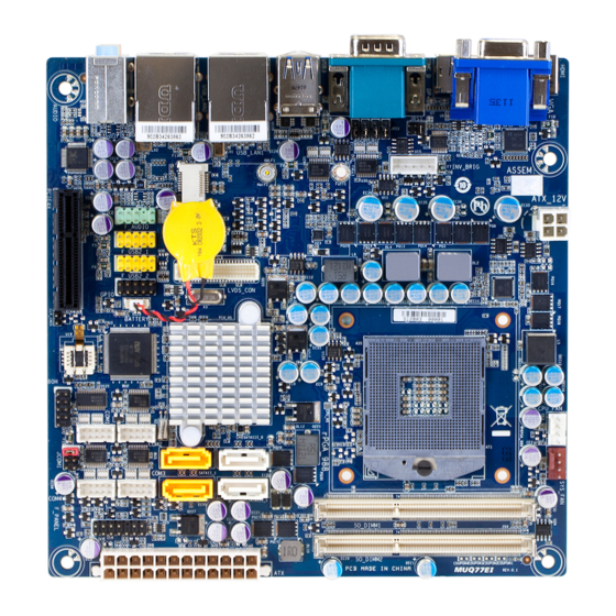
Page 5: Muq77Ei Motherboard Layout
MUQ77EI Motherboard Layout - 5 -... - Page 6 Item Code Description AUDIO Audio connectors RJ45 LAN port (top) / USB 2.0 ports USB_LAN2 (buttom) RJ45 LAN port (top) / USB 2.0 ports USB_LAN1 (buttom) USB3 USB 3.0 ports COMC_D Serial ports VGA port (top)/DisplayPort connector DP+/VGA/HDMI (right)/HDMI port (left) JRS4 RS422 Select jumper JRS5...
-
Page 7: Chapter 1 Hardware Installation
Chapter 1 Hardware Installation Installation Precautions The motherboard contains numerous delicate electronic circuits and components which can become damaged as a result of electrostatic discharge (ESD). Prior to installation, carefully read the user's manual and follow these procedures: • Prior to installation, do not remove or break motherboard S/N (Serial Number) sticker or warranty sticker provided by your dealer. -
Page 8: Product Specifications
1-2 Product Specifications Supports Intel Gen 2/3 Mobile Core i7/i5/i3 processor in Socket uPGA988 Š ® TDP 35W Š Chipset Intel BD82QM77 Platform Controller Hub (QM77) Š ® Memory 2 x SO-DIMM slots support DDR3 1333/1600MHz Š Support up 16GB Š Audio Realtek ALC887 codec... - Page 9 BIOS AMI BIOS Š Form Factor Mini ITX Form Factor; 6.75 inch x 6.75 inch Š * GIGABYTE reserves the right to make any changes to the product specifications and product-related information without prior notice. - 9 - Hardware Installation...
-
Page 10: Installing The Cpu
Installing the CPU Read the following guidelines before you begin to install the CPU: • Make sure that the motherboard supports the CPU. • Always turn off the computer and unplug the power cord from the power outlet before installing the CPU to prevent hardware damage. -
Page 11: Installing The Memory
Installing the Memory Read the following guidelines before you begin to install the memory: • Make sure that the motherboard supports the memory. It is recommended that memory of the same capacity, brand, speed, and chips be used. • Always turn off the computer and unplug the power cord from the power outlet before installing the memory to prevent hardware damage. -
Page 12: Back Panel Connectors
Back Panel Connectors Video Port The video in port allows connect to video in, which can also apply to video loop thru function. HDMI Port The HDMI (High-Definition Multimedia Interface) provides an all-digital audio/video interface to transmit the uncompressed audio/video signals and is HDCP compliant. Connect the HDMI audio/video device to this port. The HDMI Technology can support a maximum resolution of 1920x1200 pixel but the actual resolutions supported depend on the monitor being used. - Page 13 MIC In (Pink) The default MIC In jack. Microphone cab be connected to MIC In jack. Connection/ Speed LED Activity LED Connection/Speed LED: Activity LED: State Description State Description Orange 1 Gbps data rate Blinking Data transmission or receiving is occurring Green 100 Mbps data rate No data transmission or receiving is occurring...
-
Page 14: Internal Connectors
Internal Connectors 15 16 ATX1 JRS4 ATX_12V JRS5 SATAIII_0/SATAIII_1 JRS2 SATAII_1/SATAII_0 JRS3 CPU_FAN F_PANEL SYS_FAN GPIO DISPLAY_BRT F_USB2_2 COM4 F_USB2_1 COM3 F_AUDIO COM2 LVDS COM1 BATTERY JCOM1 CLR_CMOS JRS1 JLVDS_EN Read the following guidelines before connecting external devices: • First make sure your devices are compliant with the connectors you wish to connect. • Before installing the devices, be sure to turn off the devices and your computer. - Page 15 1/2) ATX/ATX_12V (2x4 12V Power Connector and 2x12 Main Power Connector) With the use of the power connector, the power supply can supply enough stable power to all the components on the motherboard. Before connecting the power connector, first make sure the power supply is turned off and all devices are properly installed.
- Page 16 DEBUG PORT 3) SATAIII_0/SATAIII_1 (SATA 6Gb/s Connectors) The SATA connectors conform to SATA 6Gb/s standard and are compatible with SATA 3Gb/s and 1.5Gb/s standard. Each SATA connector supports a single SATA device. Pin No. Definition SATAIII_0 SATAIII_1 SATAIII_0 SATAIII_1 DEBUG PORT DEBUG PORT 4) SATAII_1/SATAII_0(SATA 3Gb/s Connectors)
- Page 17 5/6) CPU_FAN/SYS_FAN (CPU Fan/System Fan Headers) The motherboard has one 4-pin CPU fan header (CPU_FAN), one 4-pin (SYS_FAN) system fan headers. Most fan headers possess a foolproof insertion design. When connecting a fan cable, be sure to connect it in the correct orientation (the black connector wire is the ground wire). The motherboard supports CPU fan speed control, which requires the use of a CPU fan with fan speed control design.
- Page 18 8/9/10/11) COM4/COM3/COM2/COM1 (Serial Port Headers) The COM header can provide one serial port via an optional COM port cable. For purchasing the optional COM port cable, please contact the local dealer. COM1 COM2 COM4 COM3 COM1 COM2 COM3 COM4 Pin No. Definition Pin No. Definition Pin No. Definition Pin No. Definition...
- Page 19 13) JRS1 (RS232/RS422/RS485 Select Header) 1-2 Close: RS232 (Default setting) 3-4 Close: RS422 5-6 Close: RS485 Pin No. Definition RS232 RXD Signal RS422 RXD Signal RS485 RXD Signal 14/15/16/17) JRS4/JRS5/JRS2/JRS3 (RS232/RS422/RS485 Mode Select Jumper) JRS2 Pin No. Definition JRS4JRS5JRS2JRS3 RS485 B Signal -NDCDC_D NDCDC 1-2 Close: RS485...
- Page 20 18) F_PANEL (Front Panel Header) Connect the power switch, reset switch, speaker, chassis intrusion switch/sensor and system status indicator on the chassis to this header according to the pin assignments below. Note the positive and negative pins before connecting the cables. Pin No. Signal Name Definition Hard Disk LED Signal anode (+)
- Page 21 F_AUDIO F_PANEL Smart Ca 19) GPIO (GPIO Header) F_PANEL F_AUDIO Pin No. Definition PCH_GPIO35 PCH_GPIO39 PCH_GPIO36 PCH_GPIO68 PCH_GPIO37 F_PANEL PCH_GPIO69 PCH_GPIO38 IR/CIR PCH_GPIO70 PCH_GPIO27 PCH_GPIO71 F_PANEL 20/21) F_USB2__2/F_USB2_1 (USB Headers) The headers conform to USB 2.0/1.1 specification. Each USB header can provide two USB ports via an optional USB bracket. For purchasing the optional USB bracket, please contact the local dealer. PWR_LED F_USB F_USB2_1...
- Page 22 22) F_AUDIO (Front Panel Audio Header) F_AUDIO F_PANEL Smart Card Reader The front panel audio header supports Intel High Definition audio (HD) and AC'97 audio. You may connect your chassis front panel audio module to this header. Make sure the wire assignments of the module connector match the pin assignments of the motherboard header. Incorrect connection between the module connector and the motherboard header will make the device unable to work or even damage it.
- Page 23 23) LVDS (LVDS Headers) LVDS stands for Low-voltage differential signaling, which uses high-speed analog circuit techniques to provide multigigabit data transfers on copper interconnects and is a generic interface standard for high-speed data transmission. Pin No. Definition Pin No. Definition LCD_VCC3 LCD_VCC3 PID1...
- Page 24 24) BATTERY (Battery cable connector) The battery provides power to keep the values (such as BIOS configurations, date, and time information) in the CMOS when the computer is turned off. Replace the battery when the battery voltage drops to a low level, or the CMOS values may not be accurate or may be lost. Pin No. Definition RTC Reset •...
- Page 25 26) LVDS_EN (LVDS Function Jumper) 1-2 Close: Enable LVDS function. (Default setting) 2-3 Close: Disable LVDS function. - 25 - Hardware Installation...
-
Page 26: Chapter 2 Bios Setup
Chapter 2 BIOS Setup BIOS (Basic Input and Output System) records hardware parameters of the system in the CMOS on the motherboard. Its major functions include conducting the Power-On Self-Test (POST) during system startup, saving system parameters and loading operating system, etc. BIOS includes a BIOS Setup program that allows the user to modify basic system configuration settings or to activate certain system features. When the power is turned off, the battery on the motherboard supplies the necessary power to the CMOS to keep the configuration values in the CMOS. - Page 27 Main This setup page includes all the items in standard compatible BIOS Advanced This setup page includes all the items of AMI BIOS special enhanced features. (ex: Auto detect fan and temperature status, automatically configure hard disk parameters.) Chipset Northbridge and Southbridge additional features configuration. Boot This setup page provides items for configuration of boot sequence. Security Change, set, or disable supervisor and user password. Configuration supervisor password allows you to restrict access to the system and BIOS Setup. A supervisor password allows you to make changes in BIOS Setup.
-
Page 28: The Main Menu
The Main Menu Once you enter the BIOS Setup program, the Main Menu (as shown below) appears on the screen. Use arrow keys to move among the items and press <Enter> to accept or enter other sub-menu. Main Menu Help The on-screen description of a highlighted setup option is displayed on the bottom line of the Main Menu. - Page 29 BIOS Information Project Name Display the project naming information. BIOS Version Display version number of the BIOS setup utility. BIOS Build Date and Time Displays the date and time when the BIOS setup utility was created. LAN 1 MAC Address Displays LAN 1 MAC address information.
-
Page 30: Advanced Menu
Advanced Menu The Advanced menu display submenu options for configuring the function of various hardware components. Select a submenu item, then press Enter to access the related submenu screen. BIOS Setup - 30 -... -
Page 31: Acpi Settings
2-2-1 ACPI Settings ACPI Settings ACPI Sleep State Select the highest ACPI sleep state the system will enter, when the suspend button is pressed. Suspend Disabled/S1 only (CPU Stop Clock)/S3 only (Suspend to RAM). Default setting is S3 only (Suspend to RAM). - 31 - BIOS Setup... -
Page 32: Trusted Computing (Optional)
2-2-2 Trusted Computing (Optional) Configuration Security Device Support Enable/Disable BIOS support for security device. O.S will not show security device. TCG EFI protocol and INT1A interface will not be available. Options available: Enabled/Disabled. Default setting is Disabled. Current Status Information Display current TPM status information. -
Page 33: Cpu Configuration
2-2-3 CPU Configuration CPU Configuration CPU Type/ Signature / Microcode Patch / CPU Speed / Processor Cores / Intel HT Technology / Intel VT-x Technology / Intel SMX Technology / 64-bit Displays the technical specifications for the installed processor. Cache Information L1 Data Cache / L1 Code Cache / L2 Cache / L3 Cache Displays the technical specifications for the installed processor. -
Page 34: Sata Configuration
2-2-4 SATA Configuration SATA Mode Selection Select the on chip SATA type. IDE Mode: When set to IDE, the SATA controller disables its RAID and AHCI functions and runs in the IDE emulation mode. This is not allowed to access RAID setup utility. RAID Mode: When set to RAID, the SATA controllerenables both its RAID and AHCI functions. -
Page 35: Intel (R) Rapid Start Technology
2-2-5 Intel (R) Rapid Start Technology Intel (R) Rapid Start Technology Enable/Disable the Intel Rapid Start Technology (IRSTe) funciton. The IRSTe enables your system to get up and running faster from even the deepest sleep, saving time and power consumption. Option available: Enabled/Disabled. -
Page 36: Intel Txt(Lt) Configuration
2-2-6 Intel TXT(LT) Configuration Intel TXT(LT) Configuration The Intel Trusted Execution Technology (TXT) submenu is a display page for the Intel TXT information. Items on this window are non-configurable. BIOS Setup - 36 -... - Page 37 2-2-7 NCT6106D Super I/O Configuration - 37 - BIOS Setup...
- Page 38 BIOS Setup - 38 -...
- Page 39 - 39 - BIOS Setup...
-
Page 40: Nct6106D Super I/O Configuration
NCT6106D Super I/O Configuration NCT6106D Super I/O Chip Display the model name of Super IO chip. Serial Port 1/2/3/4/C/D Configuration Serial Port When enabled allows you to configure the serial port settings. When set to Disabled, displays no configuration for the serial port. Options available: Enabled/Disabled. Default setting is Enabled. Device Settings Display the Serial Port 0/1 base I/O addressand IRQ. Change Settings Change Serial Port 0/1 device settings. When set to Auto allows the server’s BIOS or OS to select a configuration. -
Page 41: Nct6106D Hw Monitor
2-2-8 NCT6106D HW Monitor Press Enter to view the Hardware Monitor screen which displays a real-time record of the CPU/system tem- perature, and fan speed, Items on this window are non-configurable. CPU/System SMART FAN Function Enable CPU/System Smart Fan function. Option available: Enabled/Disabled. Default setting is Enabled. CPU/System FAN Fail Warning Enable CPU/System Fan Stop Warning function. -
Page 42: Gpio Control
2-2-9 GPIO Control GPIO 1/GPIO 2/ GPIO 3/GPIO 4/ GPIO 5/ GPIO 6/ GPIO 7/GPIO 8/GPIO 9/GPIO10 Configure the GPIO control Option available: Low/High. Default setting is Low. BIOS Setup - 42 -... -
Page 43: Network Stack
2-2-10 Network Stack Network stack Enable/Disable UEFI network stack. Options available: Enabled/DIsabled. Default setting is Disabled. - 43 - BIOS Setup... -
Page 44: Cpu Ppm Configuration
2-2-11 CPU PPM Configuration EIST (Enhanced Intel SpeedStep Technology) Conventional Intel SpeedStep Technology switches both voltage and frequency in tandem between high and low levels in response to processor load. Options available: Enabled/Disabled. Default setting is Enabled. Turbo Mode When this feature is enabled, the processor can dynamically overclock one or two of its four processing cores to improve performance with applications that are not multi-threaded or optimized for quad-core processors. -
Page 45: Intel (R) 82579Lm Gigabit Network Connection
2-2-12 Intel (R) 82579LM Gigabit Network Connection - 45 - BIOS Setup... - Page 46 PORT CONFIGURATION MENU NIC Configuration Link Speed Change link speed duplex for current port. Options available: AutoNeg/10Mbps Half/10Mbps Half/10Mbps Half/100Mbps Full. Default setting is AutoNeg. Wake On LAN Enable/Disable Wake On LAN feature. Options available: Enabled/DIsabled. Default setting is Enabled. Blink LEDs (range 0-15 seconds) Blink LEDs for the specified duration (up to 15 seconds).
-
Page 47: Chipset Menu
Chipset Menu Onboard LAN 1/2 Enable/Disable onboard LAN 1/2 controllers. Options available: Enabled/Disabled. Default setting is Enabled. Onboard Audio Enable/Disable onboard audio controller. Options available: Auto/Enabled/Disabled. Default setting is Enabled. Erp Support Enable/Disable Erp support function. Options available: Enabled/Disabled. Default setting is Disabled. Restore AC Power Loss This option provides user to set the mode of operation if an AC / power loss occurs. -
Page 48: Boot Menu
Boot Menu The Boot menu allows you to set the drive priority during system boot-up. BIOS setup will display an error message if the drive(s) specified is not bootable. Boot Configuration Bootup NumLock State Allows you to select power-on state for NumLock function. Options available: On/Off. Default setting is On. Fast Boot If enabled, the system will speed the boot up time. -
Page 49: Csm Parameters
2-4-1 CSM Parameters CSM parameters Press Enter to configure the advanced items. CSM (Compatibility Support Module) Launch Enable/Disable Compatibility Support Module (CSM) launch. Options available: Enabled/Disabled. Default setting is Enabled. • The following five items appears and configurable when the Launch CSM is set to Enabled. • If the Launch CSM is set to Disabled, the following five items will not be able to support Legacy mode. - Page 50 Other PCI device ROM priority For PCI devices other than Network, Mass storage or Video device, defines which OpROM to launch. Options available: UEFI OpROM/Legacy OpROM. Default setting is UEFI OpROM. BIOS Setup - 50 -...
-
Page 51: Security Menu
Security Menu The Security menu allows you to safeguard and protect the system from unauthorized use by setting up ac- cess passwords. There are two types of passwords that you can set: • Adminstrator Password Entering this password will allow the user to access and change all settings in the Setup Utility. •... - Page 52 Secure Boot Mode Define the Secure Boot Mode. Set this item to Custom to advanced items configuration. Option available: Standard/Custom. Default setting is Standard. BIOS Setup - 52 -...
-
Page 53: Image Execution Policy
2-5-1 Image Execution Policy Image Execution policy Internal FV Image Execution Policy per device path on Security Violation. Options available: Always Execute. Default setting is Always Execute. Option ROM Image Execution Policy per device path on Security Violation. Options available: Always Execute/Always Deny/Allow Execute/Defer Execute/ Deny Execute/ Query User. -
Page 54: Key Management
2-5-2 Key Management Key Management This item appears only when the Secure Boot Mode is set to Custom. Factory Default Key Provisioning Force the system to Setup Mode. This will clear all Secure Boot Variables such as Platform Key (PK), Key-exchange Key (KEK), Authorized Signature Database (db), and Forbidden Signaures Database (dbx). - Page 55 Set new KEK Press [Enter] to configure a new KEK. Append Var to KEK Press [Enter] to load additional KEK from a storage devices for an additional db and dbx management. Authorized Signature Database (DB) Display the status of Authorized Signature Database. Delete DB Press [Enter] to delete the db from your system. Set new DB Press [Enter] to configure a new db.
-
Page 56: Exit Menu
Exit Menu The Exit menu displays the various options to quit from the BIOS setup. Highlight any of the exit options then press Enter. Save Changes and Exit Saves changes made and close the BIOS setup and exit system setup. Options available: Yes/No. - Page 57 Restore Defaults Press <Enter> on this item and then press the <Y> key to load the default BIOS settings. Options available: Yes/No. Save as User Defaults Press <Enter> on this item and then press the <Y> key to save as user default settings. Options available: Yes/No.
-
Page 58: Chapter 3 Appendix
Contravention will be prosecuted. We believe that the information contained herein was accurate in all respects at the time of printing. GIGABYTE cannot, however, assume any responsibility for errors or omissions in this text. Also note that the informa- tion in this document is subject to change without notice and should not be construed as a commitment by GIGABYTE. - Page 59 Finally, we suggest that you practice other environmentally friendly actions by understanding and using the energy-saving features of this product (where applicable), recycling the inner and outer packaging (including shipping containers) this product was delivered in, and by disposing of or recycling used batteries properly. With your help, we can reduce the amount of natural resources needed to produce electrical and electronic equipment, minimize the use of landfills for the disposal of "end of life" products, and generally improve our quality of life by ensuring that potentially hazardous substances are not released into the environment and...
Need help?
Do you have a question about the MUQ77EI and is the answer not in the manual?
Questions and answers