Zotac nForce 610i-ITX User Manual
Hide thumbs
Also See for nForce 610i-ITX:
- User manual (46 pages) ,
- User manual (62 pages) ,
- User manual (74 pages)
Table of Contents
Advertisement
Quick Links
Download this manual
See also:
User Manual
Advertisement
Table of Contents

Related Manuals for Zotac nForce 610i-ITX


Summary of Contents for Zotac nForce 610i-ITX
-
Page 2: Electronic Emission Notices
Electronic Emission Notices WARNING! Federal Communications Commission (FCC) Statement This equipment has been tested and found to comply with the limits for a Class B digital device, pursuant to Part 15 of FCC Rules. These limits are designed to provide reasonable protection against harmful interference in a residential installation. -
Page 3: Table Of Contents
NForce 610i/630i-ITX series Motherboard Table of Contents Motherboard Specifications ------------------------------------------------------------------- 4 Motherboard Layout------------------------------------------------------------------------------ 5 Hardware Installation ---------------------------------------------------------------------------- 7 Safety Instructions ----------------------------------------------------------------------------- 7 Preparing the Motherboard -------------------------------------------------------------------- 8 Installing the CPU ------------------------------------------------------------------------------ 8 Installing the CPU Fan ------------------------------------------------------------------------ 9 Installing Memory DIMMs -------------------------------------------------------------------- 9 Installing the Motherboard ------------------------------------------------------------------- 10 Installing the I/O Shield ----------------------------------------------------------------------- 10 Connecting Cables and Setting Switches ------------------------------------------------ 11... - Page 4 Table of Contents Environment Simulation ---------------------------------------------------------------------- 31 Equalizer Selection --------------------------------------------------------------------------- 31 Frequently Used Equalizer Setting -------------------------------------------------------- 32 Karaoke Mode ---------------------------------------------------------------------------------- 32 Mixer----------------------------------------------------------------------------------------------- 32 Playback control --------------------------------------------------------------------------- 33 Recording control -------------------------------------------------------------------------- 33 Audio I/O ------------------------------------------------------------------------------------- 34 Speaker Configuration ------------------------------------------------------------------- 35 Connector Settings ------------------------------------------------------------------------ 35 S/PDIF --------------------------------------------------------------------------------------- 36 Speaker Calibration ----------------------------------------------------------------------- 36 Microphone---------------------------------------------------------------------------------- 37...
-
Page 5: Motherboard Specifications
NForce 610i/630i-ITX series Motherboard Motherboard Specifications q Chipset NVIDIA MCP73 Series q Size Mini-ITX form factor of 170mm x 170mm q Microprocessor support Intel LGA 775 Celeron , Pentium 4, Pentium D, Core 2 Series ® ® ® q Operating systems: Supports Windows XP 32 bit/64 bit and Windows Vista 32 bit/64 bit q System Memory support Supports DDRII 533/667(DDRII 800 for NForce 630i series). -
Page 6: Motherboard Layout
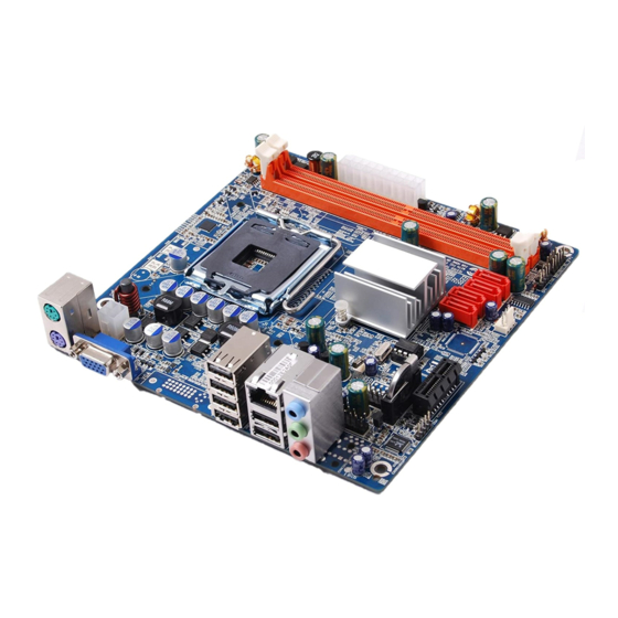
Motherboard Layout Motherboard Layout Figure 1 shows the motherboard and Figure 2 shows the back panel connectors. Figure 1. Board Layout 20-pin ATX Power Connector USB Power Select Jumper Front Panel Header Backpanel connectors SPK Header PS/2 port 5V standby selection Power Serial-ATA (SATA) Connectors 4-pin ATX_12V power connector SYS Fan connector... - Page 7 NForce 610i/630i-ITX series Motherboard Figure 2: Backpanel connectors 1. PS/2 Mouse Port 4. DVI Connector (optional for NForce630i- 2. PS/2 Keyboard Port ITX) 3. VGA Connector 5. USB Connectors 6. Port 2-Channel 4-Channel 6-Channel Blue Line-In Rear Speaker Out Rear Speaker Out Green Line-Out Front Speaker Out...
-
Page 8: Hardware Installation
Hardware Installation Hardware Installation This section will guide you through the installation of the motherboard. The topics covered in this section are: q Preparing the motherboard v Installing the CPU v Installing the CPU fan v Installing the memory q Installing the motherboard q Connecting cables and setting switches Safety Instructions To reduce the risk of fire, electric shock, and injury, always follow basic safety precations. -
Page 9: Preparing The Motherboard
NForce 610i/630i-ITX series Motherboard Preparing the Motherboard The motherboard shipped in the box does not contain a CPU and memory. You need to purchase these to complete this installation. Installing the CPU Be very careful when handling the CPU. Make sure not to bend or break any pins on the back. -
Page 10: Installing The Cpu Fan
Hardware Installation Installing the CPU Fan There are many different fan types that can be used with this motherboard. Follow the instruction that came with your fan assembly. Be sure that the fan orientation is correct for your chassis type and your fan assembly. Installing Memory DIMMs Your new motherboard has two 1.8V 240-pin slots for DDR2 memory. -
Page 11: Installing The Motherboard
NForce 610i/630i-ITX series Motherboard Use the following procedure to install memory DIMMs into the slots on the mother- board. Note that there is only one gap near the center of the DIMM slot. This slot matches the slot on the memory DIMM to ensure the component is installed properly. 1. -
Page 12: Connecting Cables And Setting Switches
Hardware Installation Connecting Cables and Setting Switches This section takes you through all the connections and switch settings necessary on the motherboard. This will include: q Power Connections v 20-pin ATX power (PW1) v 4-pin ATX 12V power (PW2) q Internal Headers v SPDIF Out Header (Optional) v SPK Connector v Front panel Header... -
Page 13: 20-Pin Atx Power (Pw1)
NForce 610i/630i-ITX series Motherboard 20-pin ATX Power (PW1) PW1 is the main power supply connector located along the edge of the board next to the DIMM slots. Make sure that the power supply cable and pins are properly aligned with the connector on the motherboard. Firmly plug the power supply cable into the connector and make sure it is secure. -
Page 14: Spdifout Header(Optional)
Hardware Installation SPDIF Out Header (Optional) This header provides a SPDIF (Sony/Philips Digital Interface) output to digital multimedia device through coaxial connector. CN7 - Pin Definition Assignment SPDIF-out +3.3V SPK Connector SPK - Pin Definition Assignment VCC NC SPK-... -
Page 15: Front Panel Header
NForce 610i/630i-ITX series Motherboard Front Panel Header The front panel header on this motherboard is one connector used to connect the following four cables: q PWRLED Attach the front panel power LED cable to these two pins of the connector. The Power LED indicates the system’s status. -
Page 16: Usb Headers
Hardware Installation USB Headers This motherboard contains six USB 2.0 ports that are exposed on the rear panel of the chassis (Figure 2). The motherboard also contains one 10-pin internal header (for NFORCE 610i series) or two 10-pin internal headers (for NFORCE 630i series) onboard. -
Page 17: Audio
NForce 610i/630i-ITX series Motherboard Audio The audio connector supports HD audio standard and provides two kinds of audio output choices: the Front Audio, the Rear Audio. The front Audio supports re-tasking function. FP-S Pin Definition Assignment MIC2(L) GND MIC(R) -ACZ-DET Front Audio(R) Reserved FAVDIO - JD... -
Page 18: Connecting Serial Ata Cables(Optional)
Hardware Installation Connecting Serial ATA Cables The Serial ATA II connector is used to connect the Serial ATA II device to the motherboard. These connectors support the thin Serial ATA II cables for primary stor- age devices. The current Serial ATA II interface allows up to 3 Gb/s data transfer rate. There are four serial ATA connectors on the motherboard that support AHCI and RAID configurations. -
Page 19: Expansion Slots
NForce 610i/630i-ITX series Motherboard Expansion Slots The NVIDIA MCP73 motherboard contains one PCI Express x1 slot. PCI Express x1 Slot PCI Express x1 Slots_PCIE2 (Optional) There is one PCI Express x1 slot that is designed to accommodate less bandwidth- intensive cards, such as a modem or LAN card. The PCI Express x1 slot provides 250 MB/sec bandwidth. -
Page 20: Jumper Settings
Hardware Installation Jumper Settings This chapter explains how to configure the motherboard’s hardware. Before using your computer, make sure all jumpers and DRAM modules are set correctly. Refer to this chapter whenever in doubt. JP1-CMOS Clear Jumper Selection 1-2* Normal* CMOS Clear JP2-PS/2 Port 5V Standby Power Selection Selection... -
Page 21: Configuring The Bios
NForce 610i/630i-ITX series Motherboard Configuring the BIOS This section discusses how to change the system settings through the BIOS Setup menus. Detailed descriptions of the BIOS parameters are also provided. Enter BIOS Setup The BIOS is the communication bridge between hardware and software. Correctly setting the BIOS parameters is critical to maintain optimal system performance. -
Page 22: Main Menu
Configuring the BIOS Main Menu This menu gives you an overview of the general system specifications. The BIOS automatically detects the items in this menu. Note: Note that the data in gray is non-changeable, and the others are for selection. q AMI BIOS Displays the auto-detected BIOS information q Processor Display the auto-detected CPU specification q System Memory Displays the auto-detected system memory q System time... -
Page 23: Advanced Menu
NForce 610i/630i-ITX series Motherboard Advanced Menu The Advanced menu items allow you to change the setting for the CPU and other system devices. Press <enter> to display the configuration options: CPU Configuration The items in this menu show the CPU-related information that the BIOS automatically detects. -
Page 24: Acpi Configuration
Configuring the BIOS q IDE Detect Time Out The items allow you to select the time out value for detecting ATA/ATAPI devices. q ATA (PI) 80pin cable detection The items allow you to select the mechanism for detecting 80pin ATA(PI) cable. ACPI Configuration The items in this menu allow you to setting General ACPI configuration, Advanced ACPI Configuration and Chipset ACPI Configuration. -
Page 25: Boot Menu
NForce 610i/630i-ITX series Motherboard Boot Menu The Boot menu items allow you to change the system boot options. Press <enter> to display the configuration options: Boot settings configuration The items allow you to configure Boot settings. Press <enter> To display the configuration options: q Quick Boot Enabling this item allows the BIOS to skip some power on self tests while booting... -
Page 26: Chipset Menu
Configuring the BIOS Chipset Menu The chipset menu items allow you to change the advanced chipset settings. Press <enter> to display the sub-menu: NorthBridge/MCP73 Configuration The items allow you to configure north bridge features, including Memory, Graphic, Video, and so on. SouthBridge Configuration The items allow you to configure south bridge features, including USB, HDA, PCIE Port, Onboard Lan/1394, CPU GTL REF, and so on. -
Page 27: Pc Health
NForce 610i/630i-ITX series Motherboard PC Health Menu The PC Health menu items allow you to monitor the parameters for critical voltages, temperatures and fan speeds. Press <enter> to display the sub-menu: CPU SmartFan This item allows you to enable and disable the control of the CPU fan speed by changing the CPU temperature. -
Page 28: Discard Changes And Exit
Configuring the BIOS Save Change and Exit Once you are finished making your selections, choose this option from the Exit menu to ensure the values you selected are saved to the CMOS RAM. An onboard backup battery sustains the CMOS RAM so it stays on even when the PC is turned off. When you select this option, a confirmation window appears. -
Page 29: Installing Drivers And Software
NForce 610i/630i-ITX series Motherboard Installing Drivers and Software Note: It is important to remember that before installing the driver CD that is shipped in the kit, you need to load your operating system. The motherboard supports Windows XP 32bit and 64bit and is Vista-capable. The kit comes with a CD that contains utility drivers and additional software. Drivers Installation 1. - Page 30 Installing Drivers and Software...
- Page 31 NForce 610i/630i-ITX series Motherboard 3. Follow the below for HDA sound driver installing. 4. At last,you can open below page that provides information about the hardware devices on this motherboard,and check whether finish your installation.
-
Page 32: Realtek Hd Audio Driver Setup
Installing Drivers and Software Realtek HD Audio Driver Setup Getting Started After Realtek HD Audio Driver being installed (insert the driver CD and follow the on-screen instructions),“Realtek HD Audio Manager” icon will show in System tray as below. Double click the icon and the control panel will appear: Sound Effect After clicking on the “Sound Effect”... -
Page 33: Frequently Used Equalizer Setting
NForce 610i/630i-ITX series Motherboard Frequently Used Equalizer Setting Realtek recognizes the needs that you might have.By leveraging our long experience at audio field,Realtek HD Audio Sound Manager provides you certain optimized equalizer settings that are frequently used for your quick enjoyment. How to Use Other than the buttons “Pop”... -
Page 34: Playback Control
Installing Drivers and Software Playback control Mute You may choose to mute single or multiple volume controls or to completely mute sound output. Tool Show the following volume control √ This is to let you freely decide which volume control items to be displayed, total 13 items to be chosen. -
Page 35: Audio I/O
NForce 610i/630i-ITX series Motherboard Mute You may choose to mute single or multiple volume controls or to completely mute sound input. Tool Show the following volume controls √ This is to let you freely decide which volume control items to be displayed. Advanced controls. -
Page 36: Speaker Configuration
Installing Drivers and Software Speaker Configuration Step 1: Plug in the device in any available jack. Step 2: Dialogue “connected device” will pop up for your selection. Please select the device you are trying to plug in. If the device is being plugged into the correct jack,you will be able to find the icon beside the jack changed to the one that is same as your device. -
Page 37: S/Pdif
NForce 610i/630i-ITX series Motherboard S/PDIF Short for Sony/Philips Digital Interface,a standard audio file transfer format.S/PDIF allows the transfer of digital audio signals from one device to another without having to be converted first to an analog format. Maintaining the viability of a digital signal prevents the quality of the signal from degrading when it is converted to analog. -
Page 38: Microphone
Installing Drivers and Software Microphone This page is designed to provide you better microphone / recording quality. Below picture indicates both “Noise Suppression” & “Acoustic Echo Cancellation” are both enabled. Noise Suppression If you feel that the background noise, especially the sound generated from the fan inside PC, is too loud? Try “Noise Suppression”, which allows you to cut off and suppress disturbing noise. -
Page 39: Audio Demo
NForce 610i/630i-ITX series Motherboard Audio Demo The section “3D Audio Demo” grants you another possibility to enjoy your sound. The Audio Demo allows you to listen to sound in an extraordinary way. Information This section provides information about your current system audio device. -
Page 40: Sata Raid User Manual
Installing Drivers and Software SATA RAID User Manual Setting up the BIOS 1. Setting your computer, then press Delete to enter the Bios setup. 2. Use the arrow keys to select Ad vanced menu.When enter the Ad vanced, use the arrow keys to select the Item “IDE Configuration”. -
Page 41: Entering The Raid Bios Setup
NForce 610i/630i-ITX series Motherboard Entering the RAID BIOS Setup 1. After rebooting your computer, wait until you see the RAID software promptint you to press F10. 2. The NVIDIA RAID Utility–Define a New Array window appears 3. In the RAID Mode field, use the UP or Down ARROW key to select a RAID Mode. The supported RAID modes include Mirroring (RAID 1), Striping (RAID 0) and Stripe Mirroring (RAID 0+1), Spanning(JBOD) and RAID 5. -
Page 42: Installing The Raid Drives
Installing Drivers and Software 7. After that, then Array List screen displaying the RAID array you created will appear. If you want to set the disk array as boot device, use the UP or DOWN ARROW key to select the array and press B. The Boot section will show Yes. 8. - Page 43 NForce 610i/630i-ITX series Motherboard 2. Press F6 and wait a few moments for the Windows Setup screen to appear. 3. Specify the NVIDIA drivers. (1) Insert the floppy that has the RAID driver, press S, then press Enter. (2) Select “NVIDIA RAID CLASS DRIVER” and then press Enter.
- Page 44 Installing Drivers and Software (3) Press S again at the Specify Devices screen, then press Enter. (4) Select “NVDIA Nforce Storage Controller” and then press Enter. 4. Press Enter to continue with Windows XP Installation. Be sure to leave the floppy disk inserted in the floppy drive until the blue screen portion of Windows XP installation is completed, then take out the floppy.
- Page 45 NForce 610i/630i-ITX series Motherboard 291-M0AF3-04...