Table of Contents
Advertisement
Quick Links
Advertisement
Table of Contents

Related Manuals for Zotac GeForce 6100-VALUE


Summary of Contents for Zotac GeForce 6100-VALUE
-
Page 2: Electronic Emission Notices
Electronic Emission Notices WARNING! Federal Communications Commission (FCC) Statement This equipment has been tested and found to comply with the limits for a Class B digital device, pursuant to Part 15 of FCC Rules. These limits are designed to provide reasonable protection against harmful interference in a residential installation. -
Page 3: Table Of Contents
GeForce6100-Value motherboard Table of Contents Motherboard Specifications ------------------------------------------------------------------- 4 Motherboard Layout------------------------------------------------------------------------------ 6 Hardware Installation ---------------------------------------------------------------------------- 8 Safety Instructions ----------------------------------------------------------------------------- 8 Preparing the motherboard ------------------------------------------------------------------ 8 Installing the CPU ------------------------------------------------------------------------- 9 Installing the CPU Fan ------------------------------------------------------------------- 9 Installing Memory Modules ------------------------------------------------------------- 10 Installing the motherboard ------------------------------------------------------------------- 11 Installing the I/O Shield ------------------------------------------------------------------ 11 Securing the Motherboard into the Chassis ---------------------------------------- 11... - Page 4 Table of Contents Boot Device Priority ----------------------------------------------------------------------- 25 Hard Disk Drivers -------------------------------------------------------------------------- 25 Removable Drivers ------------------------------------------------------------------------ 25 Security Menu ----------------------------------------------------------------------------------- 26 Change Supervisor/User Password -------------------------------------------------- 26 Boot Sector Virus Protection ----------------------------------------------------------- 26 PC Health Menu -------------------------------------------------------------------------------- 27 PC Health ----------------------------------------------------------------------------------- 27 Chipset Menu ----------------------------------------------------------------------------------- 27 NorthBridge Configuration -------------------------------------------------------------- 27 SouthBridge MCP61 Configuration --------------------------------------------------- 27...
-
Page 5: Motherboard Specifications
GeForce6100-Value motherboard Motherboard Specifications q Chipset v NVIDIA MCP61P series ® q Size v Micro ATX form factor of 9.6 inch x 7 inch q Microprocessor support v AMD Phenom II (x4)/Athlon II/Sempron with socket AM3 (TDP max:65W) ® q Operating systems: v Supports Windows XP 32 bit/64 bit, Windows Vista 32 bit/64 bit and Windows 7 32bit/64bit q System Memory support... -
Page 6: Expansion Slots
Motherboard Specifications q Green Function v Supports ACPI (Advanced Configuration and Power Interface) v Suspend to DRAM supported (STR) v RTC timer to power-on the system v AC power failure recovery q Onboard Graphics Support v Integrates GeForce 6100 engine core v Supports DirectX9.0 q Expansion Slots v One PCI Express x16 Graphics slot... -
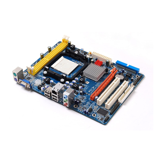
Page 7: Motherboard Layout
GeForce6100-Value motherboard Motherboard Layout 1.5V 1.5V DDR3-2 DDR3-1 SATA-2 SATA-1 PCIE1 SPDIF PCI 1 F_USB1 PCI 2 FLOPPY Figure 1. Board Layout 1. DDR3 slots 12. FLOPPY connector (optional) 2. CPU socket 13. LPT header (optional) 3. CPU fan connector 14. - Page 8 Rear Panel Figure 2: Backpanel connectors 1. PS/2 Mouse Port 2. PS/2 Keyboard Port 3. VGA Port 4. USB Ports Lan Port with LEDs to indicate status. · Green/Light Up/Blink = 10 Mbps/Link/Activity · Green/Light Up/Blink = 100 Mbps/Link/Activity 6. Port 2-Channel 4-Channel 6-Channel...
-
Page 9: Hardware Installation
GeForce6100-Value motherboard Hardware Installation This section will guide you through the installation of the motherboard. The topics covered in this section are: q Preparing the motherboard v Installing the CPU v Installing the CPU fan v Installing Memory Modules q Installing the motherboard v Installing the I/O shield v Securing the Motherboard into the Chassis q Connecting cables and setting switches... -
Page 10: Installing The Cpu
Hardware Installation Installing the CPU Be very careful when handling the CPU. Make sure not to bend or break any pins on the back. Hold the processor only by the edges and do not touch the bottom of the processor. Use the following procedure to install the CPU onto the motherboard. -
Page 11: Installing Memory Modules
GeForce6100-Value motherboard Installing Memory Modules This motherboard accommodates two memory modules. It can support two 240-pin DDR3 1333/1066/800. The total memory capacity is 8 GB. You must install at least one module in any of the two slots. Refer to the following recommendations to install the memory modules. -
Page 12: Installing The Motherboard
Hardware Installation Installing the Motherboard The sequence of installing the motherboard into the chassis depends on the chassis you are using and if you are replacing an existing motherboard or working with an empty chassis. Determine if it would be easier to make all the connections prior to this step or to secure the motherboard and then make all the connections. -
Page 13: Connecting Cables And Setting Switches
GeForce6100-Value motherboard Connecting Cables and Setting Switches This section takes you through all the connectors and switch settings necessary on the motherboard. This will include: q Power Connectors v 24-pin ATX Power Connector v 4-pin ATX_12V Power Connector q Internal Headers/Connectors v SPDIF-Out Header v COM Header v Front Panel Header... -
Page 14: 24-Pin Atx Power
Hardware Installation 24-pin ATX Power Connector-PW1 PW1 is the main power supply connector. Make sure that the power supply cable and pins are properly aligned with the connector on the motherboard. Firmly plug the power supply cable into the connector and make sure it is secure. PW1-Pin Definition Signal Signal... -
Page 15: Spdif In/Out Header (Optional)
GeForce6100-Value motherboard SPDIF-In/Out Header-SPDIF (optional) This header provides a SPDIF (Sony/Philips Digital Interface) Input & output to digital multimedia device through coaxial connector. SPDIF-Pin Definition Assignment 1.5V 1.5V SPDIF-out VCC3 SPDIF Serial Port Connector-COM (optional) COM - Pin Definition Signal Signal... -
Page 16: Front Panel Header
Hardware Installation Front Panel Header-FP1 The front panel header on this motherboard is one connector used to connect the following four cables: q PWR LED Attach the front panel power LED cable to these two pins of the connector. The Power LED indicates the system’s status. -
Page 17: Usb Headers (Optional)
GeForce6100-Value motherboard USB Headers-F_USB1/F_USB3 (optional) This motherboard contains four USB 2.0 ports that are exposed on the rear panel of the chassis (Figure 2). The motherboard also contains two 10-pin internal headers onboard. The onboard headers are optional. Note. Secure the bracket to either the front or rear panel of your chassis (not all chassis are equipped with the front panel option). -
Page 18: Fp Audio Header
Hardware Installation FP Audio Header-FP_S1 The audio connector supports HD audio standard and provides two kinds of audio output choices: the Front Audio, the Rear Audio. The front Audio supports re-tasking function. FP_S1-Pin Definition Assignment Assignment 1.5V 1.5V MIC2(L) MIC(R) -ACZ-DET Front Audio(R) Reserved... -
Page 19: Floppy Disk Drive Connector
GeForce6100-Value motherboard Floppy Disk Drive Connector-FLOPPY The motherboard provides a standard floppy disk drive connector that supports 360K, 720K, 1.2M, 1.44M and 2.88M floppy disk types. 1.5V 1.5V LPT Connector-LPT (optional) LPT - Pin Definition 1 STROBE 10 GND 19 ACK* 2 ALF* 11 PD4 20 GND... -
Page 20: Connecting Serial Ata Cables (Optional)
Hardware Installation Connecting Serial ATA Cables (optional) The Serial ATA II connector is used to connect the Serial ATA II device to the motherboard. These connectors support the thin Serial ATA II cables for primary storage devices. The current Serial ATA II interface allows up to 3 Gb/s data transfer rate. There are two serial ATA connectors on the motherboard that support IDE and RAID configurations. -
Page 21: Expansion Slots
GeForce6100-Value motherboard Expansion Slots The motherboard contains three expansion slots, one PCI Express slot and two PCI slots. For a full list of PCI Express x16 graphics card supported by this motherboard. 1.5V 1.5V PCIE1 PCI1 PCI2 PCI Slots-PCI1~PCI2 (optional) The two PCI slots support many expansion cards such as a LAN card, USB card, SCSI card and other cards that comply with PCI specifications. -
Page 22: Jumper Settings
Hardware Installation Jumper Settings This chapter explains how to configure the motherboard’s hardware. Before using your computer, make sure all jumpers and DRAM modules are set correctly. Refer to this chapter whenever in doubt. J1H1-Clear CMOS J1H1 Selection 1-2* Normal* Clear CMOS JP2-PS/2 Power Selection Selection... -
Page 23: Configuring The Bios
GeForce6100-Value motherboard Configuring the BIOS This section discusses how to change the system settings through the BIOS Setup menus. Detailed descriptions of the BIOS parameters are also provided. Enter BIOS Setup The BIOS is the communication bridge between hardware and software. Correctly setting the BIOS parameters is critical to maintain optimal system performance. -
Page 24: Advanced Menu
Configuring the BIOS Advanced Menu The Advanced menu items allow you to change the settings for the CPU and other system devices. Press <Enter> to display the configuration options: CPU Configuration The items in this menu show the CPU-related information that the BIOS automatically detects. -
Page 25: Floppy Configuration
GeForce6100-Value motherboard q Hard Disk Write Protect This item will be effective only if the device is accessed through BIOS. q IDE Detect Time Out (Sec) The item allows you to select the time out value for detecting ATA/ATAPI devices. q ATA (PI) 80pin Cable detection The item allows you to select the mechanism for detecting 80pin ATA(PI) cable. -
Page 26: Boot Menu
Configuring the BIOS Boot Menu The Boot menu items allow you to change the system boot options. Press <Enter> to display the configuration options: Boot Settings Configuration The items allow you to configure Boot settings. Press <Enter> To display the configuration options: q Quick Boot Enabling this item allows the BIOS to skip some power on self tests while booting... -
Page 27: Security Menu
GeForce6100-Value motherboard Security Menu The security menu items allow you to change the system security settings. Press <enter> to display the configuration options: Change Supervisor/User Password Select this item to set or change the supervisor/user password. The Supervisor/user Password item on top of the screen shows the default not installed. After you set a password , this item shows installed. -
Page 28: Pc Health Menu
Configuring the BIOS PC Health Menu Select PC Health from the BIOS Setup Utility menu to display the System menu. PC Health These items display the monitoring of the overall inboard hardware health events, such as CPU temperature, Memory voltage and so on. Chipset Menu The chipset menu items allow you to change the advanced chipset settings. -
Page 29: Exit Menu
GeForce6100-Value motherboard Exit Menu The exit menu items allow you to load the option or failsafe default values for the BIOS items, and save or discard your changes to the BIOS items. Press <Enter> to display the sub-menu: Save Changes and Exit Select this item and press <Enter>... -
Page 30: Flash Update Procedure
Configuring the BIOS Flash Update Procedure The program AFUDOS XX.ROM is included on the driver CD (D:\Utility\AFUDOS XX.ROM). Please follow the recommended procedure to update the flash BIOS, as listed below. 1. Create a DOS-bootable floppy diskette. Copy the new BIOS file (just obtained or downloaded) and the utility program AFUDOS XX.ROM to the diskette. -
Page 31: Installing Drivers And Software
GeForce6100-Value motherboard Installing Drivers and Software Note: 1. It is important to remember that before installing the driver CD that is shipped in the kit, you need to load your operating system. The motherboard supports Windows XP 32 bit/64 bit; Windows Vista 32 bit/64 bit and Windows 7 32bit/64bit. - Page 32 Installing Drivers and Software...
- Page 33 GeForce6100-Value motherboard follow the instructions below to install the sound Left-click HDA sound driver, and driver. 4. At last, you can enter Device Manager interface that provides information about the hardware devices on this motherboard, and check if the installation is finished.
-
Page 34: Realtek Hd Audio Driver Setup
Installing Drivers and Software Realtek HD Audio Driver Setup Getting Started After Realtek HD Audio Driver being installed (insert the driverCD and follow the on- screen instructions), “Realtek HD Audio Manager” icon will show in System tray as below. Double click the icon and the control panel will appear: Sound Effect After clicking on the “Sound Effect”... -
Page 35: Frequently Used Equalizer Setting
GeForce6100-Value motherboard Equalizer Selection The Equalizer section allows you to create your own preferred settings by utilizing this tool. In standard 10 bands of equalizer, ranging from 100Hz to 16KHz are available: Frequently Used Equalizer Setting Realtek recognizes the needs that you might have. By leveraging our long experience at audio field, Realtek HD Audio Sound Manager provides you certain optimized equal- izer settings that are frequently used for your quick enjoyment. -
Page 36: Mixer
Installing Drivers and Software Mixer Realtek HD Audio Sound Manager integrates Microsoft’s “Volume Control” functions into the Mixer page. This gives you the advantage to you to create your favorite sound effect in one single tool. Playback control Mute You may choose to mute single or multiple volume controls or to completely mute sound output. -
Page 37: Recording Control
GeForce6100-Value motherboard With this function, you will be able to have an audio chat with your friends via headphone (stream 1 from front panel) while still have music (stream 2 from back panel) playing. At any given period, you can have maximum 2 streams operating simultaneously. Recording control Mute You may choose to mute single or multiple volume controls or to completely mute... -
Page 38: Audio I/O
Installing Drivers and Software Audio I/O Realtek HD Audio Manager frees you from default speaker settings. Different from before, for each jack, they are not limited to perform certain functions. Instead, now each jack is able to be chosen to perform either output (i.e. playback) function or input (i.e. -
Page 39: Speaker Configuration
GeForce6100-Value motherboard Speaker Configuration Step 1: Plug in the device in any available jack. Step 2: Dialogue “connected device” will pop up for your selection. Please select the device you are trying to plug in. * If the device is being plugged into the correct jack, you will be able to find the icon beside the jack changed to the one that is same as your device. -
Page 40: Global Connector Settings
Installing Drivers and Software Global Connector Settings Click to access global connector settings Mute rear panel when front headphone plugged in √ Once this option is checked, whenever front headphone is plugged, the music that is playing from the back panel, will be stopped. Disable front panel jack detection (option) √... - Page 41 GeForce6100-Value motherboard Output Sampling Rate √ 44.1KHz: This is recommended while playing CD 48KHz: This is recommended while playing DVD or Dolby. 96KHz: This is recommended while playing DVD-Audio. Output Source √ Output digital audio source: The digital audio format (such as .wav, .mp3, .midi etc) will come out through S/PDIF-Out.
-
Page 42: Microphone
Installing Drivers and Software Microphone This page is designed to provide you better microphone / recording quality. Below picture indicates both “Noise Suppression” & “Acoustic Echo Cancellation” are both enabled. Noise Suppression If you feel that the background noise, especially the sound generated from the fan inside PC, is too loud? Try “Noise Suppression”, which allows you to cut off and sup- press disturbing noise. -
Page 43: 3D Audio Demo
GeForce6100-Value motherboard 3D Audio Demo The section “3D Audio Demo” grants you another possibility to enjoy your sound. The Audio Demo allows you to listen to sound in an extraordinary way. Information This section provides information about your current system audio device. -
Page 44: Sata Raid User Manual
SATA RAID User Manual SATA RAID User Manual Setting up the BIOS Setting your computer, then press <Delete> to enter BIOS SETUP UTILITY. Use the arrow key to select Advanced menu. When enter the Advanced menu, select the Item “IDE Configuration”. Press <Enter>... -
Page 45: Entering The Raid Bios Setup
GeForce6100-Value motherboard Entering the RAID BIOS Setup After rebooting your computer, wait until you see the RAID software promptint you to press F10. The NVIDIA RAID Utility –Define a New Array window appears In the RAID Mode field, use the UP or Down ARROW key to select a RAID Mode. The supported RAID modes include Mirroring (RAID 1), Striping (RAID 0) and Stripe Mirroring (RAID 0+1), Spanning(JBOD) and RAID 5. - Page 46 SATA RAID User Manual Press F7 after selecting the target hard disks. A message which says “Clear disk data?” will appear. If you are sure to clear the data in the selected hard drives, press Y. (If the hard drives contain previously created RAID array, you need to press Y to clear the data from the hard drives.) After that, then Array List screen displaying the RAID array you created will appear.
-
Page 47: Installing The Raid Drives
GeForce6100-Value motherboard Installing the RAID Drivers After you complete the RAID BIOS setup, boot from the windowsXP CD. The Windows Setup program starts. Press F6 and wait a few moments for the Windows Setup screen to appear. Specify the NVIDIA drivers. (1). - Page 48 SATA RAID User Manual (2). Select “NVIDIA RAID CLASS DRIVER” and then press Enter. (3). Press S again at the Specify Devices screen, then press Enter. (4). Select “NVDIA Nforce Storage Controller” and then press Enter.
- Page 49 GeForce6100-Value motherboard Press Enter to continue with Windows XP Installation. Be sure to leave the floppy disk inserted in the floppy drive until the blue screen portion of Windows XP installation is completed, then take out the floppy. Follow the instructions on how to install Windows XP. During the GUI portion of the install you might be prompted to click Yes to install the RAID driver.
Need help?
Do you have a question about the GeForce 6100-VALUE and is the answer not in the manual?
Questions and answers