Table of Contents
Advertisement
SAVE THIS MANUAL
FOR
FUTURE REFERENCE
OWNER'S
MANUAL
MODEL NO.
351.226711
CAUTION:
READ ALL
INSTRUCTIONS
CAREFULLY!
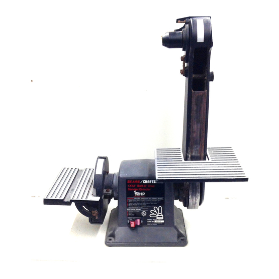
.A/P /CRR
FTSMRN
l"x 6" BELT & DISC SANDER
• safety Instructions
• assembly
• operating instructions
• replacement
parts
Sold by SEARS, ROEBUCK
AND CO., Chicago,
IL 60684 U.S.A. ©
Part NO. 3899.00
May 1991
Advertisement
Table of Contents

Related Manuals for Craftsman 351.226711


Summary of Contents for Craftsman 351.226711
- Page 1 SAVE THIS MANUAL FUTURE REFERENCE OWNER'S MANUAL MODEL NO. 351.226711 .A/P /CRR FTSMRN l"x 6" BELT & DISC SANDER CAUTION: READ ALL INSTRUCTIONS • safety Instructions CAREFULLY! • assembly • operating instructions • replacement parts Sold by SEARS, ROEBUCK AND CO., Chicago, IL 60684 U.S.A.
- Page 2 FULL ONE YEAR WARRANTY ON SEARS/CRAFTSMAN 1" x 6" BELT & 015C SANDER If Within one full year tom the date of purchase, this Sset_ Cmfleman 1" x 6" Belt & Dlso Sender fells due to e defect in material or wodunanchlp,...
- Page 3 CONTENTS Unpaeldng end Checking Contents ... Wmmmty ........ TOOLSNeeded ......Goal 8eloty Immmotkme for Power Tcolo ...... As_mb_ ....... Operetlon ....... Salety InIWmotlene for Bolt & Disc Sender ....Malntermr_e ......0 & 0 Motor Speclfk:atlone Trouble Shooting ......end Ei$Ctlrlsal Requirements ....
- Page 4 MOTOR SPECIFICATIONS AND ELECTRICAL REQUIREMENTS PROPERLY MOTOR GROUNDED The belt and disc lander Is mmembled with motor 8nd wiringreadied ,., an _eTal i_t of the tool The 120 Volt AC permanent epla €_q_c_ motor has the renewing qx_ncatk_: M_ Devek¢_ Horsepower ....Voltage ........
- Page 5 ELECTRICAL CONNECTIONS WARNING: MAKE 8URE THE UNIT 18 OFF AND DISCONNECTED FROM THE POWER 8OURCE BEFORE IN8PECTING WIRING. •r_ motor wxl wlrl_ m k_mlled u _ _ U_ wr_ dk_ram (m F_re 1). The motor Is auen_ed with an apflrowd thnm oo_ ductor €old to be used on 120 volts u Indk:ated.
- Page 6 ASSEMBLY Lift the disc table so both tn.lnnions are shoulderod CAUTION: DO NOT A'rFEMPT ASSEMBLY IF PARTS ARE MISSING. USE OWNER'S MANUAL agelnst the guide pips and tighten the knobs. TO ORDER REPLACEMENT PARTS. Position dtsc table so the edge of disc table end abrasive disc are parallel and the gap between them Is 1/16'.
- Page 7 OPERATING INSTRUCTIONS (Continued) TENSIONING ABRASIVE BELT ADJUSTING BELT TABLE ANGLE Tension ks created by a spring loaded Cam shaft (Key TO adjust the angle of the belt tal_e, loosen the socket No.32). head bolt (Key NO` S2) and adJuetto d'm desired angle. Uee a combination square to set the belt table at 45"...
- Page 8 OPERATING INSTRUCTIONS (Contlnued) _0o, abrasiveused can be changedtOa dlffarentgrit ro_acgnothe aJum_num €.8C. Addltlonslaluminum dlace are avsHable,Use I sep- arate elumlnumdlsofor _ch gritslze used. Interal_nge the ilun_num dlscto el_nge _ size. Refll_e dlse table. ADJUSTING DISC TABLE ANGLE dll_ tal_e 18IKllUllllll01o from 45" to gO* for beveled work.
- Page 9 MAINTENANCE (Continued) LUBRICATION Replace any damaged or mlsldng parts. Use the perte I_ to order parts. The shielded _ besdng_l In this sander are per- manomly IUl_ted lit the factory. They require no Any _lempt to repalr the motor may create e heze_ further lubrlcelk)n, unless rel_r Is done by s qualified service technlclarL...
- Page 10 F_re S - F_:i_TW_ pam m_...
- Page 11 REPLACEI NT PARTS LIST PART PART DESCRIP'flON QI"_'. DESCRIPTION QTY. 3896.00 Ro(o¢ 3329.00 Handle wjlmob 333O.OO Bolt table 3897.00 Stzd_ Z924.0O Bdl table bracket 3896.00 1304.00 Switch with key 38ge.00 STD5110O; * #I0-24x 1/4" ScreWr I:Bnhud 3304.0O 330S.0O 3306.00 STD51100_ * dP10-24xS/16' Screw, pan head 1603.00 Rutdxrfoot STD5.0O_ : _lO-_xlrZ'Scrow,pa.hoad...
Need help?
Do you have a question about the 351.226711 and is the answer not in the manual?
Questions and answers
What is the part # for the 1”x42” belt for model #351.226711 And we’re can it be purchased from.
The part number for the 1”x42” abrasive belt for Craftsman model 351.226711 is 928409 (fine), 928410 (medium), or 928411 (coarse).
This answer is automatically generated