Table of Contents
Advertisement
Available languages
Available languages
Advertisement
Table of Contents

Related Manuals for Craftsman 351.215140


Summary of Contents for Craftsman 351.215140
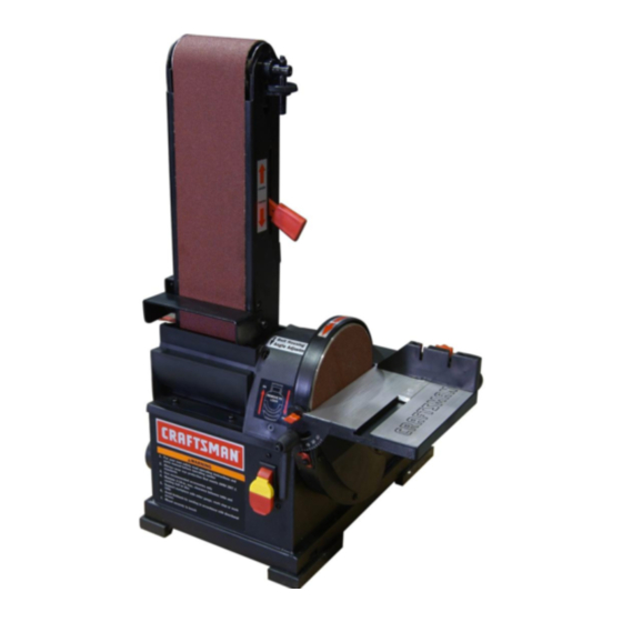
- Page 1 Operator's Manual 36" Belt 6" Disc SANDER Model No. 351.215140 CAUTION: Read and follow all Safety Rules and Operating Instructions before First Use of this Product. Keep this manual with tool. Sears, Roebuck and Coo, Hoffman Estates, IL 60179 U.S.A. www,sears.com/craftsrnan 26350,01 Draft (06/22!05)
- Page 2 ON CRAFTSMAN TOOL • Keep all parts in working order. Check to determine that the If this Craftsman tool fails due to a defect in material or guard or other parts will operate properly and perform their intended function. workmanship within one year from the date of purchase CALL f-800-4-MY-HOME®...
-
Page 3: Tools Needed
nor bystanders will have to stand in line with the wood while using the tool. Allow room so that belt assembly can be positioned horizontally. Refer to Figure 1. • Press a foot onto each corner of the base of the sander. Check for shipping damage. -
Page 4: Grounding Instructions
Figure 6- Using Table with Belt Figure 4 * Remove Cover and Attach Abrasive Disc ATTACH TABLE Refer to Figures 5 and 6. The included table is used with both the disc and belt. Refer to Figures 7, 8 and 9, pages 4 and 5. To use the table with the disc: POWER SOURCE... -
Page 5: Motor Specifications
• Many cover plate screws, water pipes and outlet boxes are not properly grounded. To ensure proper ground, grounding The Craftsman Belt and Disc Sander is constructed of rugged means must be tested by a qualified electrician. die cast aluminum and cast iron providing stabilityand vibra- tion-free operation. -
Page 6: Specifications
• Arsenic and chromium from chemically-treated lumber. SPECIFICATIONS Your risk from these e_posures vary, depending on how often Belt size ........4 x 36" you do this type of work. To reduce your exposure to these Belt platen area ....... 5 x 9"... - Page 7 Tracking Nut Tension Lever Figure 13 - Table Tilts Down 45 ° HORIZONTAL BELT SANDING WITH WORK STOP Refer to Figure 14. • Remove table and stud from belt assembly, • Tilt belt assembly from vertical to horizontal position and secure in position.
-
Page 8: Replacing Abrasive Disc
• Check tracking. See "Adjusting Belt Tracking", page 6. • Finishing end grain: It is more convenient to finish ends of • Assemble in reverse order. long workpieces with the abrasive belt in a vertical position. Position table on belt side of sander. Move work evenly across abrasive belt. - Page 9 Becertain m otor iskept clean a nd isfrequently vacuumed KEEP TOOL IN REPAIR free ofdust. • If power cord is worn, cut, or damaged in any way, have it Use soap and water toclean p ainted parts, rubber parts and replaced immediately.
- Page 10 Model 351.215140 Figure 18 - Replacement Parts Illustration for Belt Housing...
- Page 11 PART NO. DESCRIPTION QTY. PART NO. DESCRIPTION QTY. STD840506 5-0.Smm Hex Nut* 23682,00 Side Cover STD870516 5-0.8 × 16mm Socket Head Bolt* 23663.00 Dust Deflector STD863510 5-0.8 × 10mm Pan Head Screw* 08686.00 4-0.7 x 15mm Pan Head Screw 23694,00 Platen with Label STD870510 5-0.8 x 10me Socket Head Bolt*...
- Page 12 Model 351.215140 Figure 19 - Replacement Parts Illustration for Motor and Disc...
- Page 13 KEYI QTY. DESCRIPTION QTY. DESCRIPTION PART NO. PART NO. Line Cord Hook 23066.00 23652.00 Miter Gauge Assembly 5-0.8 x 10mm Sockel Head Bolt* Knob STD870510 23653.00 Body with Labels 23654.00 Looking Handle Bolt 23668,00 6rnm Flat Washer* STD851006 23669.00 Rubber Pad Table 23655.00 2.5mm Split Pin...
- Page 14 COMPLETA DE UN AIqO PARA HERRAMIENTA • Mantenga a los nifios fuere des lugar de trabajo. Haga que CRAFTSMAN su taller sea a pr_eba de niSos. Use candados, intermptores Si esta herramienta Craftsman fallara pot cause de defectos en el...
- Page 15 EL OPERADOR DEBE SABER COMO USAR de cabeza hueca de M6 x 16 (2), Arandela de seguridad de M6 (2), Aradela plane de M6 (6), Tuerca hexagonal de M6 (4), Llave LA HERRAMIENTA hexagonal de 3 y 5 mm y Llave de extremo abierto de 13rnm. •...
- Page 16 INSTALACION DE LA MESA Consulte las Figuras 5 y 6. El mesa incluido se utiliza con ambos, el disco y la correa. Para utilizar la mesa con el disco: • Coloque la mesa er_ la protecci6n del disco y fije con las perillas.
- Page 17 1as Normas pare Instalaciones El$ctdcas (National Electric Code) y 1as c6digos y regulaciones locales. ADVERTENClA: Esta tarea deber_ ser realizada par un electriaista calificado. Consuite las Figures 7, 8 y 9 en las p&gina_ 17 y 18. Se puede usar temporalmente un adaptador de 3 puntas a 2 FUENTE DE AUMENTACION...
-
Page 18: Precauciones De Seguridad
La corrsa abrasiva debe avanzar haeia abajo. DESCRIPCION • Lije de acuerdo con Ise fiechas de direcciSn pare evitar ice La Lijadora de correa y disco de Craftsman estd construida de contragolpse. aluminio fiJndido a presi6n y hierro |orjado robusto para propor- •... - Page 19 INTERRUPTER DE ON/OFF (ENCENDIDO/APAGADO) Consulte ]a Figura 10. El interrupter de encendido y apagado se encuentra en la parte delantera superior dereoha del base. Pare encender la lijadora, cambie la posici6n de] interrupter ala posici6n superior. Pare apagar la lijadora, cambie la posiOiSn del interrupter ala posici6n inferior.
- Page 20 • Acabado de las piezaa targas: Utilice la ¢orrea en posicibn AJUSTE DEL ANGULO DE LA MESA horizontal y con el tope de seguridad puesto. Aplique ec4a- Consulte la Figura 13. manta la presibn sufir_Jentepare permitir qua la correa • Pare ajustar el dngulo de la mesa, afloje la rnanilla, incline abraalva elimine el material.
- Page 21 CAMBIO DE LA CORREA ABRASIVA Consulte la Figura 16. • La cortes abrasiva se debe cambiar ouando est_ desgastada, rots o viddada, • Retire elcon}unto de la mesa. • Retire el indicador, luego deslice la cubierta hacia aniba y hacia fuera del desviador (o deflector) de polvo.
- Page 22 SINTOMA CAUSA(S) POSIBLE(S) MEDIDA CORRECTIVA El motor no arranca 1. Voltaje bajo 1. Verifiqueel voltaje corractode la Ifr,ea de alimentaci6n 2. Oircuito abierto an el motor o 2. Inspeccione todas ]as conexiones de ccoductores conexiones sueltas en el motor Dam ver que no haya conexlones sualtas o abier_as 3.
- Page 23 NOTAS...
- Page 24 Your Home For repair-in your home-of all major brand appliances, lawn and garden equipment, or heating and cooling systems, no matter who made it, no matter who sold it! For the replacement parts, accessories owner's manuals that you need to do-it-yourself. For Sears professional installation of home appliances...
Need help?
Do you have a question about the 351.215140 and is the answer not in the manual?
Questions and answers