Table of Contents
Advertisement
Available languages
Available languages
Operator's Manual
CRRFISMRN °
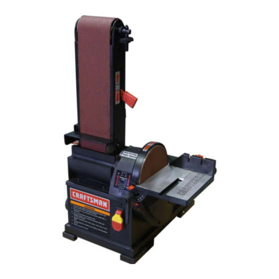
4 x 36" Belt
6" Disc
SANDER
Model No.
351.215140
CAUTION:
Read and follow
all Safety Rules and Operating
Instructions
before First Use
of this Product. Keep this
manual with tool.
Sears, Roebuck and Co., Hoffman
Estates, IL 60179 U.S.A.
www.sears.com/craftsman
23650.03 Draft (04/27/07)
Advertisement
Table of Contents

Related Manuals for Craftsman 351.215140


Summary of Contents for Craftsman 351.215140
- Page 1 6" Disc SANDER Model No. 351.215140 CAUTION: Read and follow all Safety Rules and Operating Instructions before First Use of this Product. Keep this manual with tool. Sears, Roebuck and Co., Hoffman Estates, IL 60179 U.S.A. www.sears.com/craftsman 23650.03 Draft (04/27/07)
- Page 2 TOOL wires of the extension cord should be of the correct gauge. If this Craftsman tool fails due to a defect in material or work- ° Keep visitors at a safe distance from work area. manship within one year from the date of purchase, call 1- °...
- Page 3 • Turn machine off if it jams. Belt jams when it digs too • Combination Square deeply into workpiece. (Motor force keeps it stuck in the • Phillips Screwdriver work.) MOUNT SANDER • Support workpiece with miter gauge, belt platen or work table.
- Page 4 • Center the abrasive disc onto the aluminum disc and press on firmly and evenly. Replace disc cover. Figure 6 - Using Table with Belt Figure 4 - Remove Cover and Attach Abrasive Disc Refer to Figures 7, 8 and 9, pages 4 and 5. ATTACH TABLE Refer to Figures 5 and 6.
- Page 5 • Many cover plate screws, water pipes and outlet boxes are DESCRIPTION not properly grounded. To ensure proper ground, grounding The Craftsman Belt and Disc Sander is constructed of rugged means must be tested by a qualified electrician. die cast aluminum and cast iron providing stability and vibra- tion-free operation.
- Page 6 SPECIFICATIONS The sander can be locked from unauthorized use by locking the switch. To lock the switch: Belt size ........4 x 36" • Turn the switch to OFF position and disconnect sander Belt platen area ........ 5 x 9" from power source.
- Page 7 HORIZONTAL BELT SANDING WITH BACK STOP • Quickly turn switch ON and OFF again. If belt moves to one side, continue adjusting tracking nut as needed to center Refer to Figure 14. belt on drums. Back stop supports the workpiece when sanding on the belt with the belt assembly in the horizontal position.
- Page 8 USING MITER GAUGE ° Additional abrasive belts are available (See Recommended Accessories, page 13). Refer to Figure 15. • Push tension lever towards drive drum to tension belt. • Use the miter gauge for securing the work and holding the proper angle while sanding.
- Page 9 KEEP TOOL IN REPAIR Any attempt to repair motor may create a hazard unless repair is done by a qualified service technician. Repair • If power cord is worn, cut, or damaged in any way, have it service is available at your nearest Sears store. replaced immediately.
- Page 10 Model 351.2151 40 Figure 18 - Replacement Parts Illustration for Belt Housing ,..b...
- Page 11 PART NO. DESCRIPTION QTY. PART NO. DESCRIPTION QTY. 23682.00 Side Cover STD840508 5-0.8mm Hex Nut* STD870516 5-0.8 x 16mm Socket Head Bolt* 23683.00 Dust Deflector STD863510 5-0.8 x 10mm Pan Head Screw* 08685.00 4-0.7 x 15mm Pan Head Screw 23694.00 Platen with Label STD870510 5-0.8 x 10mm Socket Head Bolt*...
- Page 12 Model 351.21 5140 Figure 19 - Replacement Parts Illustration for Motor and Disc ,,,,,.L...
- Page 13 PART NO. DESCRIPTION QTY. PART NO. DESCRIPTION QTY. 23652.00 23666.00 Line Cord Hook Miter G auge A ssembly Knob STD870510 5-0.8 x 10ram Socket Head Bolt* 23653.00 23654.00 Locking H andle Body w ithLabels STD851006 6ram Flat W asher* 23668.00 Bolt 23655.00 Table...
- Page 14 • Mantenga el Area de trabajo limpia. Las Areas de trabajo GARANTIA COMPLETA DE UN ANO PARA HERRAMIENTA desordenadas atraen accidentes. CRAFTSMAN • No use herramientas mecanicas en ambientes peligrosos. Siesta herramienta Craftsman fallara por causa de defectos en el...
- Page 15 • Mantenga todas las partes listas para funcionar. Revise el La lijadora viene montada como una unidad. Es necesario protector u otras piezas para determinar si funcionan correcta- Iocalizar y tomar en cuenta las piezas adicionales que deben mente y hacen el trabajo que deben hacer.
- Page 16 INSTALACION DE LA MESA Consulte las Figuras 5 y 6. El mesa incluido se utiliza con ambos, el disco y la correa. Para utilizar la mesa con el disco: • Coloque la mesa en la protecci6n del disco y fije con las perillas.
- Page 17 las Normas para Instalaciones Electricas (National Electric Code) y los c6digos y regulaciones locales. ADVERTENClA: Esta tarea deber_, ser realizada por un Consulte las Figuras 7, 8 y 9 en las p_.ginas 17 y 18. electricista calificado. Se puede usar temporalmente un adaptador de 3 puntas a 2 FUENTE...
- Page 18 DESCRIPCION • Asegurese que el disco gire en el sentido de las manillas La Lijadora de correa y disco de Craftsman est,. construida del reloj. La correa abrasiva debe avanzar hacia abajo. aluminio fundido a presi6n y hierro forjado...
- Page 19 AJUSTE DE LA POSlClON CONJUNTO AVlSO: Si se extrae la Ilave con el interruptor en la posici6n ON DE LA CORREA (encendido), se puede Ilevar este a la posici6n OFF (apagado) pero no a la de encendido. Consulte la Figura 12. •...
- Page 20 PARA LIJAR LA CORREA EN POSIClON • Mueva la pieza de trabajo a trav6s del lado inferior (izquierdo) HORIZONTAL Y EL TOPE DE SEGURIDAD INSTALADO del disco abrasivo. Sujete firmemente la pieza de trabajo con las dos manos; mantenga los dedos alejados del disco Consulte la Figura 14.
- Page 21 • Vuelva a montar en el orden inverso. ADVERTENCIA: AsegtJrese de que la unidad est6 desconecta- da de la fuente de alimentaci6n electrica antes de tratar de dar servicio o retirar cualquier componente. LIMPIEZA Mantenga la m_tquina y el taller limpios. No permita que el aserrin se acumule...
- Page 22 SINTOMA MEDIDA CORRECTIVA CAUSA(S) POSIBLE(S) El motor no arranca 1. Voltaje bajo 1. Verifique el voltaje correcto de la linea de alimentaci6n 2. Circuito abierto en el motor o 2. Inspeccione todas las conexiones de conductores conexiones sueltas en el motor para ver que no haya conexiones sueltas o abiertas 3.
- Page 23 NOTAS...
- Page 24 Your Home For repair _ in your home _ of all major brand appliances, lawn and garden equipment, or heating and cooling systems, no matter who made it, no matter who sold it! For the replacement parts, accessories owner's manuals that you need to do-it-youre For Sears professional installation of home appliances and items like garage door openers and water heaters.
Need help?
Do you have a question about the 351.215140 and is the answer not in the manual?
Questions and answers