Table of Contents
Advertisement
Owner's Manuam
2/3 HP (Maximum
400-3000
RPM
518 Inch Chuck
Developed)
33oWNCH VARIABLE
SPEED
LL PRESS
CAUTmONo`
Before using this Drill Press,
read this manual and follow
all its Safety Rules and
Operating
Instructions.
o Safety Instructions
o Ynstallation
o Operation
,, Maintenance
o Parts List
,, Espa_ol
@ustemer
He_lp L_ne
1-8ee.843.1682
Sears, Roebuck
and COo, Hoffman
Estates,
mL60179 USA
Part No, 137229130002
Advertisement
Table of Contents

Related Manuals for Craftsman 137.229130


Summary of Contents for Craftsman 137.229130
- Page 1 Owner's Manuam 2/3 HP (Maximum Developed) 400-3000 518 Inch Chuck 33oWNCH VARIABLE SPEED LL PRESS CAUTmONo` o Safety Instructions o Ynstallation Before using this Drill Press, read this manual and follow o Operation all its Safety Rules and ,, Maintenance Operating Instructions.
- Page 2 SECTION PAGE GENERAL SAFETY INSTRUCTIONS WEAR VOUR ALWAYS WEAR EYE PROTECTION. Any drill press BEFORE USING THE DRNLL PRESS Warranty ..............can throw foreign objects into Product Specifications ............the eyes which could cause Safety is a combination of common sense, staying alert Safety _nstructions ............
- Page 3 24.WARNING: Dust g enerated fromcertain materials c anbe GROUNDING _NSTRUCT_ONS i4. SECURE WORK. Use clamps or a vise to hold the Fig, A injurious t oyourhealth. Always operate d rillpress in wel! work when practical. It's safer than using your hand ventilated areasandprovide forproper dustremoval.
- Page 4 UNPACKING YOUR DR LL PRESS UNPACKING AND CHECKING AVAILABLE ACCESSORnES CONTENTS Visit your Sears Hardware Department or see the Sears Power and Hand Tools Catalog for the following accessories: Carefully unpack the drill press and all its parts, and compare against the list below. Drill bits Hold-Down and Guide To protect the drill press from moisture, a protective coating...
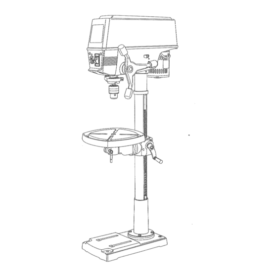
- Page 5 BASE - Supports the drill press. For additional stability, FENCE -Attaches to the table to align the workpiece or for Speed chart Speed control knob Belt guard cover holes are provided in the base to bolt the drill press to the fast repetitive drilling.
- Page 6 INSTALLING THE HEAD (FIG. D) INSTALLING THE CHUCK {FIG. F, G, and H) Clean out the tapered hole in the chuck (1) with a clean cloth. Clean tapered surfaces on the arbor (2) and spindle (3). The Drill Press head is very heavy and MUST be lifted with NSTRUCTJONS iNSTALLING THE TABLE (F_G.
- Page 7 BEVEL SCALE (FIG. L and tgl) DRNLL PRESS ADJUSTMENTS When the indicator on the control knob (1) is in line Using a rubber mallet, ptasticqipped hammer, or a block of wood and a hammer, firmly tap the chuck with the desired speed on the speed scale, turn the NOTE: The bevel scale has been included to measure upward into position on the spindle shaft.
- Page 8 / OFF SWITCH PANEL (FIG. O) DRILLING TO A SPECIFIC DEPTH (FIG. R) LOCKING THE CHUCK AT THE DESIRED DEPTH Fig. P Drilling a blind hole (not all the way through workpiece) The ON / OFF switch has a removable, yellow plastic key, (FIG.
- Page 9 HOLDING A DRILLING LOCATION BASIC OPERATION SAFETY POSmTtONING THE TABLE AND WORKPIECE When using a drill press vise, always fasten it to Using a centerpunch or sharp nail, make an indentation the table. (FIG. U, and V) To get the best results and minimize the likelihood of personal in the workpiece where you want the hole.
- Page 10 MAINTAiNiNG YOUR DR LL PRESS TROUBLESHOOTnNG GUDE Remove the speed control knob and collar. Replace the pulley cover on the head assembly and tighten the pulley cover screws. Install the speed control knob and collar. For your own safety, turn the switch OFF and remove the To avoid injury from an accidental start, turn the switch OFF and always remove the plug from the power source before plug from the power source outlet before maintaining or making any adjustments.
- Page 11 MODEL NO. 137.229130 When servicing use onty CRAFTSMAN replacement parts. Use of any other parts may create a HAZARD or cause product damage. Any attempt to repair or replace electrical parts on this Drill Press may create a HAZARD unless repair is done by a qualified service technician.
- Page 12 13" VARIABLE SPEED DRILL PRESS PARTS LUST MODEL NO. 137.229130 13" VARIABLE SPEED DRILL PRESS _ODEL NO. 137.229130 PARTS LUST FOR SCHEMATIC SCHEMATIC B Part No. Description Size 2668BBDA29 Pan head screw M5X0.8-30 1046l 101 Plunger housing 2701QZD612 Hex. nut 1/2X20UNF T=6.5 2701QZD610 Hex, nut...
- Page 13 13" VARIABLE SPEED DRILL PRESS PARTS LIST MODEL NO, 137.229130 13" VARIABLE SPEED DRILL PRESS MODEL NO. 137.229130 PARTS MST FOR SCHEMATIC C SCHEMATIC C Part No. Descrip_on $1ze 2138MBL703 Hex. wrench 3-57 2138MBL704 Hex. wrench 4-64 2807BB08HJA1 Power cable assembly t 0463501 Shaft sleeve 250l NBDN 16...
- Page 14 t3" VAR|ABLE SPEED DR_LL PRESS PARTS LiST MODEL NO, t37.229130 13, VARIAE_LE,SPEED DRILL PRESS • :,; ::: MODELNO, 137,229130 PA_T$ LIST FOR SCHEMATIC D (MOTOR) SCHeMATiC _ (MOTOr) Part NOo Description Size 2668BBDBB3 Pan head screw M4X0.7-t65 2504MBC004 Tooth washer 82042031!_ Front end ball 2504MZC005...
Need help?
Do you have a question about the 137.229130 and is the answer not in the manual?
Questions and answers