Table of Contents
Advertisement
Operator's
ManuaM
.3
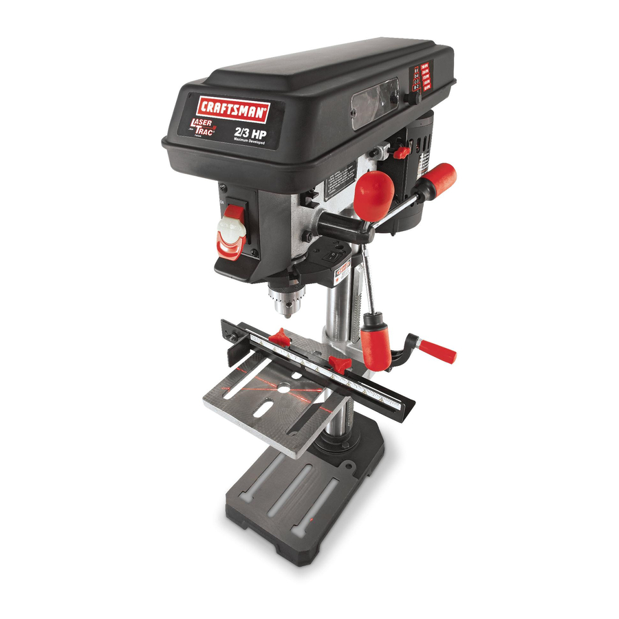
10 in. DRILL PRESS
With Laser Trac ®
Model No, 137,219000
CAUTION:
Before using this DriJl Press,
read this manual and follow
all its Safety Rules and
Operating
Instructions
o
Safety Instructions
o
Installation
®
Operation
o
Maintenance
•
Parts List
Customer
He_p Line
1-80@-843-1682
Sears, Roebuck
and Co., Hoffman
Estates,
IL 60179 USA
Visit
our Oraftsman
website:
www.sears.com/craftsman
Part No. 137219000001
Advertisement
Table of Contents

Related Manuals for Craftsman 137.219000


Summary of Contents for Craftsman 137.219000
- Page 1 Before using this DriJl Press, read this manual and follow ® Operation Maintenance all its Safety Rules and • Parts List Operating Instructions Customer He_p Line 1-80@-843-1682 Sears, Roebuck and Co., Hoffman Estates, IL 60179 USA Visit our Oraftsman website: www.sears.com/craftsman Part No. 137219000001...
- Page 2 FULL WARRANTY ON CRAFTSMAN TOOL If this Craftsman too! fails due to a defect in material or workmanship within one year from the date of purchase, CALL 1-800-4-MY-HOME ®TO ARRANGE FOR FREE REPAIR If this too! is used for commercial or rental purposes, this warranty wil! apply for only ninety days from the date of purchase.
- Page 3 14.REMOVE ADJUSTING KEYS AND WRENCHES. GENERAL SAFETY mNSTRUCTmONS Form habit of checking to see that keys and adjusting wrenches are removed from the too! before turning it BEFORE USING THIS DRILL PRESS Safety is a combination of common sense, stay alert 15NEVER LEAVE A TOOL RUNNING UNATTEND.
- Page 4 [AWARNING 14SECURE THE WORK. Use clamps or a vise to hold the work when practical, it's safer than using your hand and it frees both hands to operate tool For your own safety, do not try to use your drill press or plug it in until it is completely assembled and installed 1&WHEN using a dril! press vise, always fasten to the according to the instructions, and until you have read...
- Page 5 GROUNDING INSTRUCTIONS tNTHEEVENT OFA _,_ALFUNCTION (When using 120 volts only) Ampere Rating Total length of cord in feet BREAKDOWN, grounding provides a pathof least resistance f orelectric current a ndreduces t he riskof _lole than not mole than 100' 150' shock.
- Page 6 RECOMMENDED ACCESSORmES UNPACKING AND CHECKING CONTENTS [AWARN NG [AWARNmNG ] Use only accessories recommend for this drill press. If any part is missing or damaged, do not plug the drill Follow instructions that accompany accessories. Use of press in until the missing or damaged part is replaced, improper accessories may cause hazards.
- Page 7 UNPACKING AND CHECKING CONTENTS WWWW...
- Page 8 Depth stop nuts Depth scale pointer Beltspee_ Motor pulley Spindle pulley Depth scale Quill retu coil / spring Rack ring Table bracket Belt speed sight window Table bracket Pulley cover Bevel lock bolt lock handle Base ON/OFF Motor switch with safety key Belt tension lock knob...
- Page 9 BASE HEAD LOCKING SCREWS - Locks the head to the - Supports dril! press. For additional stability, holes are provided in base to bolt drill press to column. ALWAYS lock head in place while operating the workbench. drill press. BACKUP MATERIAL - A piece of scrap wood placed ON/OFF SWITCH - incorporates a safety switch between the workpiece and table.
- Page 10 NOTE: Table removed from bracket in illustration for ASSEMBLY JNSTRUCTmONS clarity. [AWARNmNG 1 Fig. B For your own safety, never connect plug to power source outlet until all assembly steps are complete and you have read and understood the safety and operating instructions.
- Page 11 4_Slidethetableassembly w iththerackontothe 7_Instal! t hetablecrankhandle (9)ontothewormgear column. shaft(11) onthesideofthetablesupport ( 12)_ 5_ Engage thebottom oftherack(5)withthelipofthe 8_Lineuptheflatsideoftheshaftwiththesetscrew(10) column support ( 6)_ Tighten thetablebracket l ock inthecrankhandle andtighten thescrew withthe handle (4)to lockthetableassembly tothecolumn. 3mmhexwrench provided. Fig.D Fig.F ® © INSTALLING THE HEAD (FIG.
- Page 12 tNSTALUNG FEED HANDLES (FIG.H) 4. Unlock thetablesupport l ock(4-Fig.D)andswing 1_Thread eachfeedhandle (1)intothethreaded thetableawayfromthebottom ofthechuck. holes(2)onthehubassembly ( 3)andTighten_ 5. Using a rubber m allet o r a hammer a nda blockof wood, t apthechuckontothespindle firmly (Fig.K). Fig.H Fig.K tNSTALUNG THECHUCK (FIG. J ,J ANDK) 1.
- Page 13 ADJUSTMENTS mNSTRUCTmONS FENCE ASSEMBLY (FIG. M) 1_ Align the mounting holes of the fence over the table slots. NOTE: All the adjustments for the operation of the 2. Place a washer (2) on the threaded end of the knob drill press have been completed at the factory. Due to (3).
- Page 14 NOTE: DO NOT OVERTIGNTEN and restrict quil! [AWARNING movement. To prevent persona! injury, always disconnect the plug from the power source when making any adjustments. Fig. P SPINDLE / QUILL (FIG. O) Rotate the feed handles counterclockwise to lower spindle to its lowest position. Hold the chuck and move it front to back.
- Page 15 4_ Once adjustments are completed, retighten the four [AWARNING screws (4)_ AVOID DIRECT EYE CONTACT A Laser light is radiated when the laser guide is turned Fig. R on. Avoid direct eye contact. Always un=plug the drill press from the power source before making any adjustments.
- Page 16 BASmC DRILL PRESS OPERATmONS J,AWARNING j ALWAYS lock the switch "OFF" when the drill press is NOTE: This machine incorporates view windows on the not in use by removing the safety switch key keep it in a pulley cover used to observe the location of the belL safe place.
- Page 17 Fig.U Workpieee method (Fig. W and X} 1. Mark the depth (1) of the hole on the side of the workpiece (Fig. W). 2. With the switch "OFF", bring the drill bit (2) down until the tip is even with the mark (Fig. W) 3.
- Page 18 Fig,× b. Whenever possible, position the workpiece to 3 5 7 contact the left side of the column, if it is too short or the table is tilted, use the fence provided or clamp solidly to the table, using the table s!ots. c.
- Page 19 POSITIONING THE TABLE AND WORKPtECE 2. Turn the laser "ON" and align the laser lines (x) with (FIG. AA AND BB) the indentation before turning the drill ON. 1. Lock the table (1) to the column (2) at a position so TILTING THE TABLE (FIG.
- Page 20 [AWARNING Fig. DD For your own safety, turn the switch OFF and remove the plug from the power source outlet before maintaining or lubricating your dril! press_ Frequently blow out, using an air compressor or dust vacuum, any dust that accumulates inside the motor. Wear protective safety goggles.
- Page 21 [,&WARNING To avoid injury from accidental starting, always turn switch OFF and unplug the tool before moving, replacing the blade or making adjustments. Consult your Sears Service Center if for any reason the motor will not run. PROBLEM POSSIBLE CAUSES REMEDY Noisy operation 1.
- Page 22 10 in. DRmLL PRESS MODEL NO. 137.219000 [AWARNING When servicing use only CRAFTSMAN replacement parts. Use of any other parts many create a HAZARD or cause product damage. [,_WARNING Any attempt to repair or replace electriea! parts on this Drill Press may create a HAZARD unless repair is done by a...
- Page 23 10 in. DRILL PRESS MODEL NO. 137.219000 SCHEMATIC OJJZ _0UGH 0KDH 3 2C08 OVPE 048Z 0KSQ 048K 0K7K 04WG 2C08 048P OJP44 0KQY2 04AD 06SV 0KDJ2 0KDJ 04BM 0KC62 OLWC 0L6D OKFF 2 OKUX 047X 047U...
- Page 24 Your Home For repair - in your home - of all major brand appliances, lawn and garden equipment, or heating and cooling systems, no matter who made it, no matter who sold it! For the replacement parts, accessories Operator's Manuals that you need to do-itoyourself. For Sears professional installation of home appliances...
Need help?
Do you have a question about the 137.219000 and is the answer not in the manual?
Questions and answers
laser on one side dimmer than the other. centering won't work
To fix a Craftsman 137.219000 laser that is dimmer on one side and has centering issues:
1. Replace the batteries with new AAA batteries, as low battery power can cause dimness.
2. Tap the outside bottom and side of the laser housing lightly with the butt end of a screwdriver to adjust the battery contacts.
3. Do not attempt to open the laser housing or adjust laser power, as this is forbidden and may cause damage.
4. If the issue persists, the unit may need service by the laser manufacturer or an authorized agent.
This answer is automatically generated