Table of Contents
Advertisement
Available languages
Available languages
Operator's
Manual
Snow Thrower
9.0 Horsepower
Electric Start
26-inch
Dual Stage
Model536.886261
CAUTION: Before using this product,
read this manual and follow all of its
Safety Rules and Operating Instructions.
-I=..rT=...°l -
Manual del usario
Quitanieves
de 26 pulgadas
9.0 caballos
de fuerza
(hp)
Bietapico
Arranque
el_ctrico
Modelo 536.886261
PRECAUCION:
Antes de usar este producto,
lea este manual y siga todas las reglas de
seguridad e instrucciones de operaci6n.
Sears, Roebuck
and Co., Hoffman
Estates,
IL 60179 U.S.A.
F-011050L
www.sears.com/craftsman
Advertisement
Table of Contents

Related Manuals for Craftsman 536.886261


Summary of Contents for Craftsman 536.886261
- Page 1 9.0 caballos de fuerza (hp) Bietapico Arranque el_ctrico Modelo 536.886261 PRECAUCION: Antes de usar este producto, lea este manual y siga todas las reglas de seguridad e instrucciones de operaci6n. Sears, Roebuck and Co., Hoffman Estates, IL 60179 U.S.A. F-011050L www.sears.com/craftsman...
- Page 2 SERVICE AND ADJUSTMENT BACK COVER LIMITED TWO-YEAR WARRANTY ON CRAFTSMAN SNOW THROWER For two years from the date of purchase, when this Craftsman Snow thrower is maintained, lubricated, and tuned up according to the operating and maintenance instructions in the owner's manual, Craftsman will repair, free of charge, any defect in material or workman- ship.
- Page 3 TRAINING Always wear safety glasses or eye shields during operation or while performing an ad- Read the operating and service instruction justment or repair to protect eyes from manual carefully. Be thoroughly familiar foreign objects that may be thrown from the with the controls and the proper use of the snow thrower.
- Page 4 13. Never operate the snow t hrower near en- Never store the snow thrower with fuel in closures, automobiles, window wells, the tank inside a building where ignition drop-offs, and the like without proper ad- sources are present such as hot water and justment of thesnow discharge angle.
- Page 5 Drive Clutch Forward Reverse Auger Clutch Auger Collector Engage Push To Engage Fuel FueI OilMixture Electric Starter Discharge DOWN Discharge UP Discharge LEFT Discharge RIGHT Weight Transfer Weight Transfer Transmission Ignition Key Lift Handle To Depress Pedal Insert To Run, Engage To Disengage Pull Out To Stop.
- Page 6 CONTENTS OF PARTS BAG (ACTUAL SIZE) 1 - Owner's Manual (not shown) 1 - Packet of Fuel Stabilizer (not shown) 1 - Warranty Card (not shown) *Non-Assembly Parts, found in toolbox located on belt cover 1 - Shift Lever Knob (not actual size) PARTS PACKED SEPARATELY...
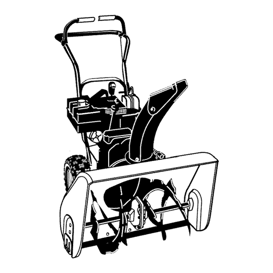
- Page 7 4_lb WARNING: Always wear safety glasses or eye shields while assembling snow thrower. TOOLS REQUIRED ASSEMBLY 1 - Knife to cut carton 2 - 1/2 inch wrenches Figure 1 (or adjustable wrenches) 2 - 9/16 inch wrenches Figure 1 shows the snow thrower in the (or adjustable wrenches) shipping position.
- Page 8 TO ASSEMBLE THE HANDLE 6. Install the fasteners that were re- CRANK ASSEMBLY moved in step 4. DO NOT tighten 1. Cut tie holding shift rod to lower until all bolts are in place. handle and move shifter to the first forward gear.
- Page 9 TO INSTALL SHIFTER KNOB 1. Thread the shifter lever knob onto NOTE: If the cables have become dis- the threaded end of the shifter le- connected, connect cables as shown in ver until it is snug against the hex Figure 8. jam nut and the lip is pointed away from the engine.
- Page 10 HOW TO SET THE SKID HEIGHT Your snow thrower is equipped with height for different conditions, see To height adjust skids on the outside of the Adjust Skid Height paragraph in the auger housing. To adjust the skid Service And Adjustment section.
- Page 11 [o] -.l_1 :_±'1 / [o]_ KNOW YOUR SNOW THROWER READ THIS OWNER'S MANUAL AND SAFETY RULES BEFORE OPERATING YOUR SNOW THROWER. Compare the illustrations with your SNOW THROWER to familiarize yourself with the location of various controls and adjustments. Save this manual for future reference.
- Page 12 [o] -.l_1 :_±'1 / [o]_ The operation of any snow thrower can the speed you desire by moving the result in foreign objects being thrown speed shifter lever left into the ap- into the eyes, which can result in se- propriate notches on the shift lever vere eye damage.
- Page 13 [e] ",.l =1 :__,'1 / [e];_ Klick Pin _/Dipstick Unlocked sition Single Wheel Drive Figure 13 Figure 14 NOTE: Make sure that the klick pin is 4. Tighten the fill cap/dipstick securely in the single wheel drive position of the each time you check the oil level.
- Page 14 [e] "J _1 :_±'1 / [e]_ Never use engine or carburetor cleaner ing the engine, be certain that you have read the following information. products in the fuel tank or permanent damage may occur. equipped with a three-wire 1. Fill the fuel tank only with a fresh, ARNING: The starter is power cord and plug and is clean, unleaded regular, unleaded...
- Page 15 [e] "J _1 :_±'1 / [e]_ COLD START 7. Push the primer button while cov- ering the vent hole as follows: Re- 1. Be sure auger drive and traction move finger from primer button drive levers are in the disengaged between primes.
- Page 16 [e] -J_1 :_±,1 / [e]_ 2. Release the starter handle and let it Disconnect spark plug wire. snap back against the starter. Do not place your hands in the If the engine still fails to start, repeat the auger or discharge chute. Use a two previous steps until the engine pry bar.
- Page 17 CUSTOMER RESPONSIBILITIES SERVICERECORDS Every Every Every Fillindates asyou Before Each Before SERVICE complete r egular Each service. Often Hours Hours Hours Season Storage DATES Change Engine Oil ......:::::::::::::::::::::: Check Spark Plug Check Fuel Check Cable Adjustment See Cable Adjustment) GENERAL RECOMMENDATIONS should be checked atleast once each...
- Page 18 PRODUCT SPECIFICATIONS CAUTION: Do not allow grease or oil to contact the rubber friction wheel or the disc drive plate. HORSEPOWER 9 HP 6. Install the bottom panel. DISPLACEMENT 19.34 cu, in. GASOLINE 4 quarts CAPACITY (unleaded) OIL CAPACITY 5W30 (20 oz capacity) SPARK PLUG: Champion RJt 9LM...
- Page 19 TO CHANGE ENGINE OIL Clean the spark plug by carefully scraping the electrodes (do not 1. Position the snow thrower so that sand blast or usa a wire brush). the oil drain plug is at the lowest point on the engine. 2.
- Page 20 raise the adjustable skids. Tighten nect the spark plug wire and the mounting nuts. See Figure 18. ARNING: Always discon- place it where it cannot NOTE: For rocky or uneven surfaces, make contact with spark plug to pre- raise the front of the snow thrower by vent accidental starting when mak- moving the skids down.
- Page 21 BELT ADJUSTMENT 5. Have someone engage auger drive clutch. Check tension on belt (op- Traction Drive Belt posite idler pulley). Belt should de- flect about 1/2 inch (12.5 mm) with The traction drive belt has constant moderate pressure Figure 20). You spring pressure and does not require may have to move idler pulley more an adjustment.
- Page 22 from the engine pulley. Replace Remove the bottom panel. the auger drive belt with an original Bolt Bottom Panel factory replacement belt available from an authorized service center. 8. Install the new auger drive belt onto the auger drive pulley and onto pulley.
- Page 23 How To Remove plate is properly secured (see The Traction Drive Belt Figure 23). If the snow thrower will not move for- ward, check the traction drive belt for wear or damage. If the traction drive belt is worn or damaged, replace the belt as follows.
- Page 24 BELT GUIDE ADJUSTMENT Control lever must be in full forward posi- tion (just contacting plastic bumper) when 1. Remove spark plug wire. checking cable length. 2. Have someone engage auger drive. 3. Measure the distance between the "Z" Fitting belt guide and belt. The distance should be 1/8 inch (3.175 ram) for guide.
- Page 25 TRACTION DRIVE CABLE ADJUSTMENT line outdoors, away from drive cable through the cable ad- WARNING: Drain the gaso- 6. Pushthe bottom of the traction fire or flame, justment bracket untilthe "Z" hook can be removed. 1. Remove the gas from the gas tank. Stand the snow thrower up on the 7.
- Page 26 HOW TO ADJUST OR REPLACE 5. Install the bottom panel (see THE FRICTION WHEEL Figure 30). 6. Tighten the bolts on each side of How To Check The Friction Wheel the bottom panel. Bolt Bottom Panel If the snow thrower will not move for- ward, check the traction drive belt, the traction drive cable or the friction wheel.
- Page 27 How To Replace The Friction Wheel If the friction wheel is worn damaged, the snow thrower will not move forward. The friction wheel must be replaced as follows. Bolt 1. Remove the gas from the gas tank. Stand the snow thrower up on the Wheel front end of the auger housing (4).
- Page 28 10. Remove the three fasteners that 16. Check the adjustment of the friction hold the friction wheel to the hub wheel. See "How To Adjust The Friction Wheel" in this section. (see Figure 36). 17. Make sure the friction wheel and the 11.
- Page 29 THE CARBURETOR pounds. Feeler Gauge If you think your carburetor needs ad- justing, see your nearest Craftsman Store. Engine performance should not be affected at altitudes up to 7,000 feet. For operation at higher elevations, con- tact your nearest Sears Store.
- Page 30 If you do not remove the gasoline, tank, fumes may reach an open use fuel stabilizer supplied with unit flame, spark or pilot light from a fur- or purchase Craftsman Fuel Stabi- nace, water heater, clothes dryer, lizer No. 3550. Add fuel stabilizer to cigarette, etc.
- Page 31 Stop engine immediately and impeller disconnect spark plug wire. Tighten all bolts and make all necessary repairs. vibration continues, have the unit serviced by a Craftsman service repairman. Unit fails to propel itself Drive belt ioose or damaged. Replace drive belt. Incorrect adjustment Adjust traction drive cable.
- Page 32 SEARS, ROEBUCK Federal and California Emission Control Systems Limited Warranty Small Off-Road Engines CALIFORNIA & US EPA EMISSION quired maintenance listed in your Owner's CONTROL WARRANTY STATEMENT Manual, but Sears, Roebuck and Co. will not deny warranty solely due to the lack of receipts The U.
- Page 33 ershall pay any charges formaking service Sears, Roebuck and Co. according to Subsec- calls and/or fortransporting theproducts tion 4 below. Any such part repaired or re- and from the place w here the inspection and/ placed under the ECS Warranty shall be orwarranty work i sperformed.
- Page 34 use shall not r educe Sears, Roebuck and Co. EMISSION-RELATED PARTS ECS Warranty obligations. INCLUDE THE FOLLOWING: 9.Unapproved add-on ormodified parts m ay 1. Carburetor Assembly and its Internal Com- not b eused t omodify orrepair aSears, Roe- ponents buck a nd C o. engine. Such u se voids this ECS a) Fuel filter Warranty and shall besufficient grounds for...
- Page 35 GARANTiA LIMITADA DE DOS AI;IOS PARA EL QUITANIEVES CRAFTSMAN Durante dos argosa partir de la fecha de compra, siempre que a este quitanieves Craftsman se le d_ mantenimiento, lubricaci6n y afinamiento de acuerdo con las instrucciones de operaci6n y man- tenimiento presentadas en et manual del propietario, Craftsman reparar&, sin cargo alguno, cual...
- Page 36 CAPACITACION combustible que se produce por el calor del motor y/o del sol. Lea atentamente las instrucciones sobre Para todas las unidades con motores de operaci6n y servicio que aparecen en el arranque el6ctrico, utilice cables de exten- manual. Familiaricese completamente si6n certificados por CSA/UL.
- Page 37 8. Cuando limpie, repare oinspeccione 19. N unca opere elquitanieves sinbuena visi- bilidad oiluminaci6n. Asegt_rese siempre unidad, asegt3rese deque labarrena/pro- pulsor ytodas l as partes m6viles se ha- detenet buena estabilidad, y sujete yah detenido. Desconecte elcable d ela firmeza el mango de la unidad. Camine; bujia ymantengalo alejado deesta para nunca corra.
- Page 38 B'_t] KtI-'] IMPORTANTE: Encontrara muchos de los simbolos siguientes en su unidad o en los impresos in- formativos que vienen con el producto. Antes de operar la unidad entienda y aprenda el objetivo de cada simbolo. Simbolos de control y operacion Despacio Rapido Arranque el_ctrico...
- Page 39 Simbolos de control y operacion Mezcla de combustible Combustible Aceite y aceite Descarga hacia Descarga hacia Descarga hacia la Descarga hacia la ABAJO ARRIBA IZQUIERDA DERECHA i' o] Transterencia de peso Transterencia de peso Llave de ignicibn Levante el mango Presione el pedal Insertar para marcha, para enganchar...
- Page 40 CONTENIDO DE LA BOLSA DE PARTES (TAMANO REAL) 1 - Manual del Propietario (no se muestra) 1 - Paquete de estabilizador de combustible (no se muestra) 1 - Tarjeta de garantia (no se muestra) *Las partes que no necesitan ensamblado se encuentran en la caja de herramientas ubicada en la cubierta de la correa.
- Page 41 gafas de seguridad o protecto- DVERTENCIA: Siempre use res para los ojos mientras en- sambla el quitanieves. HERRAMIENTAS NECESARIAS 1 - Cuchillo para cortar la caja 2 - Uave de tuercas de 1/2 pig (o Ilave de tuercas ajustable) Figura 40 2 - Uave de tuercas de 9/16 pig (o Ilave de tuercas ajustable) La Figura 40 muestra el quitanieves en...
- Page 42 COMO ENSAMBLAR EL MANGOY Palanca de embrague EL CONJUNTO DE LA MANIVELA 1. Corte los amarres que sujetan la palanca de cambios al mango Conexi6n en "Z" inferior y mueva la palanca a la primera velocidad de avance. Cable 2. Corte y deseche el amarre de pl&s- tico que sujeta el conjunto de la ma- nivela.
- Page 43 7. Conecte el eje de la manivela a la junta universal con el pasador de horquilla. Vea la Figura 45. 8. Apriete la tuerca del perno de anilla. Aseg0rese de que el perno de anilla est_ bien alineado y que la manivela pueda girar libremente.
- Page 44 cabeza redonda est_n bien apreta- ENSAMBLADO DEL CANAL DE dos. DESCARGA Gire la manivela de ajuste de direcci6n de descarga hacia la izquierda hasta que se detenga. Coloque et canal de daacatga de nieve Pemos en la parte interior de la brida y alinee los tres agujeros del canal de descarga oabeza con los agujeros de la brida det canal de...
- Page 45 CONOZCA SU QUITANIEVES LEA ESTE MANUAL DEL PROPIETARIO Y LAS REGLAS DE SEGURIDAD ANTES DE USAR USAR SU QUITANIEVES. Compare QUITANIEVES para familarizarse con las posicio- nes de los diversos controles y ajustes. Guarde este manuel para referencia en el futuro. Palanca de propul- Bot6n de arran- si6n por tracci6n...
- Page 46 La operaci6n decualquier quitanieves puede ca de cambio de velocidades a la ranura ocasionar que objetos extraSos sean l anza- apropiada del panel de control de cam- dos con fuerza hacia l osojos, Iocual podria bias. resultar en lesiones graves. Use siempre Velocidad 1,2 - Nieve mojada, pesada gafas de seguridad o protectores pars los Velocidad 3 - Nieve ligera...
- Page 47 Tapa/varilla indicadora klick asador Posici6n de _ _,.__el nivel de ac ' e desengan- Traoc,on en __ sola rueda Figura 52 NOTA: El nivel del aceite deberA estar entre la marca FULL (lleno) y Ia marca NOTA: AsegSrese de que el pasador kiick ADD (agregar) Figura 53 est_ en la posici6n de tracci6n de una sola...
- Page 48 dor e sten v acios. Use eltaz6n d edrenaje ARRANQUE DEL MOTOR del c arburador para v aciar lagasolina resi- (si la unidadest_ equipadacon un dual delacAmara del f lotador. Use gasolina arrancador electrico) fresca lasiguiente temporada. Pars m ayor informaci6n consulte lasecci6n de...
- Page 49 4. Gire l aperilla deI e strangulador hacia l a ARRANQUE DEL MOTOR derecha alaposici6n "ACTWADO". (arranquemanual) 5. Conecte elcable d ealimentaci6n Cerci6rese de que el motor tiene suficiente ja del tomacorrientes del motor. aceite. El motor deI quitanieves est@ equipa- do con un sistema de de arranque manual.
- Page 50 corto, deje el estrangulador en "DESACTI- Desconecte el cable de la bujia. VADO" y no pulse el bot6n cebador. No coloque las manos en la barrena o canal de descarga. Use una barfs de ARRANQUE CONGELADO apalancamiento para sacar el objeto atascado.
- Page 51 RESPONSABILIDADES DEL CLIENTE REGISTROSDE SERVICIO Anotelas fechss s me- Antes Cada Cada Cada Csda Antes FECHA didaque completsel de ca- A me- tempo- servicio da uso nudo horas horas horas rada guardar SERVICIO Cambiar eI aceite del motor !i!i!i!i!i!i!i!i!i!i!i!i!i!i!i!i!i!i! Revisar la bujia !i!i!i!i!i!i!i!i!i!i!i!i!i!i!i!i!i!i! to_ _!! ................
- Page 52 ESPECIFICACIONES PRECAUCI(_N: No permita que la grasa entre en contacto con la rueda de friccion ni con la placa del disco de CABALLOS 9 HP propulsibn. FUERZA 6. InstaIe el panel inferior. CILINDRADA 19,34 pig. CL_. CAPACIDAD 4 cuartos GASOLINA (sin plomo) CAPACIDAD ACEITE...
- Page 53 CAMBIO DE ACEITE 1. Asegt_rese de que la bujia este limpia. Limpiela raspando con mucho cuidado 1. Coloque el quitanieves de manera tal que ios electrodos (no use chorro de aren ni el tap6n de drenaje del aceite sea ei pun- cepillo de alambres).
- Page 54 4. Afloje las tuercas de montaje que sujetan los patines de ajuste de altura. Para bajar Ia parte delantera del quitanieves, suba el arranque accidental del mo- ADVERTENCiA: Para prevenir los patines. Apriete las tuercas de mon- tor, siempre desconecte el ca- taje.
- Page 55 AJUSTES DE LA CORREA beria coder media pulgada (12,5 mm) con presi6n moderada Correa de propulsion (Figura 59). Puede que tenga que La correa de propulsi6n tiene una mover la polea guia mas de una presi6n de resorte constante y no re- vez para conseguir la tensi6n co- rrecta.
- Page 56 3. Quite e l panel inferior. Instale una correa de propulsion de la barrena nueva original de f&- Pemo Panel inferior brica que haya comprado en un centro de servicio autorizado. 8. Instale la correa de propulsion de la barrena nueva en la polea de miento propulsion yen la polea.
- Page 57 Modo de desmontar la correa de sujeta (Figura 62). propulsion Si el quitanieves no se mueve hacia adelante, aseg_rese de que la correa de propulsi6n no est@excesivamente desgastada o dafiada. Si Io est&, reempl&cela de la siguiente manera. 1. Desconecte el cable de la bujia. 2.
- Page 58 AJUSTES DE LA CORREA GUiA Cuando revise la Iongitud del cable, la pa- lanca debe estar hacia adelante (tocando 1. Quite el cable de la bujia. et tope de plAstico). 2. Pida a alguien que ponga el propul- Accesorio "Z" sor de la barrena.
- Page 59 AJUSTES DEL CABLE DE PROPULSION solina al aire libre, lejos de propulsion porel soporte de ajus- ADVERTENCIA: Vacie la ga- 6. Meta la parteinferiordel cable de cualquier llama, te del cable hasta que pueda sacar 1. Vacie el tanque de gasolina. Levan- el gancho "Z".
- Page 60 AJUSTE 0 REEMPLAZO DE LA RUEDA DE FRICCION Revision de la rueda de friccion Si la rueda de friccion no esta en la posici6n correct& ajOstela de la Si el quitanieves no avanza, revise la siguiente manera (consulte la correa de propulsi6n per tracci6n, el ca- Figura 70).
- Page 61 Reemplazo de la rueda de friccion NOTA: Fijese especialmente en la posicion de las arandelas en el eje hexagonal. Si la rueda de fricci6n est& gastada o dafiada, el quitanieves no avanza. La rueda de fricci6n se debe cambiar de la siguiente manera. 1.
- Page 62 10. Quite los tres sujetadores que re- Revise el ajuste de la rueda de fric- tienen la rueda de friccion en el ci6n. Consulte "Ajuste de la rueda de fricci6n" en esta secci6n. cubo (consulte la Figura 75). 17. AsegQrese de que la rueda de fric- 11.
- Page 63 SEGURIDAD DE LA BARRENA cesita set ajustada, p6ngase en contacto Las barrenas estAn sujetas al eje de Ia ba- con su centro de servicio Craftsman mAs rrena con pernos de seguridad especiales. cercano, el cual tiene el equipo y la expe-...
- Page 64 Finalmente, NOTA: Una revisi6n o afinamiento anual reinstale Ia bujia y conecte el cable. hecho en un Centre de servicio Craftsman es una buena manera de asegurar que su quitanieves le brinde el maximo rendimiento OTRAS INDICACIONES Ia siguiente temporada.
- Page 65 Apriete todos los pemos y haga todas las reparaciones necesarias. Si la vibraci6n continEa, haga revisar la unidad por un tecnico especializado Craftsman. La unidad no se Correa de propulsi6n floja o Reemplace la correa de puede propulsar daSada, propulsi6n.
- Page 66 SEARS, ROEBUCK Garantia limitada de cumplimiento con el Sistema Federal de control de emisiones y con el sistema de control de emisiones del Estado de California Motores pequehos no aptos para carretera (off-road) CONTROL DE EMISIONES SISTEMA PARA EL CONTROL DE CALIFORNIA Y DE LA AGENCIA DE EMISIONES DEL FABRICANTE...
- Page 67 Sears, Roebuck and Co. o a Sears, Roebuck A. CAMPO DE APLICAOION: Esta garantia and Co. al 1-800-473-7247 (llamada gratuita de berA aplicarse a los motores peq ue5os para en E.U.A.). vehiculos off-road modelo 1995 y modelos de aSos posteriores en California (para otros es- NOTA IMPORTANTE tados, motores modelo 1997 y modelos de aSos posteriores).
- Page 68 Garantia SCE d eberA garantizarse per elresto aprobada per S ears, Roebuck and Co. p ara del P eriodo delamisma. utilizarse eneldesempeflo decualquier man- tenimiento o cambio delaGarantia SCE, la 3.Cualquier parte g arantizada yreIacionada cual se proporcionarA sin cargo alguno para e l con emisiones que seespecifique para c am-...
- Page 69 F-OOIO50M...
- Page 70 F-OOIO50M...
- Page 71 F-OOIO50M...
- Page 72 For repair of major brand appliances in your own home.,. no matter who made it, no matter who sold it! iiiiiiiiiii 1-800-4-MY-HOME SM Any,_me day night (,-800469-4663! iiiiiiiiiii www.sears.com iiiiiiiiiii TO bring in products such as vacuums, lawn equipment and electronics for repair, call for the location of your nearest Sears Parts &...
- Page 73 CRAFTSMAN 26" 9HP SNOW THROWER 536.886261 ENGINE 25-3 25-4 Ref.Drive Page Ref. Auger ENG101A Housing Page Part No. Description Part No. Description ENG{NE 1501201 GUIDE, BELT 2x97 BOLT 71060 WASHER 28x76 RETAINER 710097 SCREW 710026 FRAME ASSY 1501109 PULLEY 25-1...
- Page 74 CRAFTSMAN 26" 9HP SNOW THROWER 536.886261 ELECTRIC STARTER ES100A Part No. Description 6218 MOTOR, STARTER SCREW 6216 SCREW 6217 6219 CORD, STARTER F-O11050L...
- Page 75 CRAFTSMAN 26" 9HP SNOW THROWER 536.886261 FRAME \ lo5 Ref. Auger Housing 120qo Page Ref. Drive Page Part No. Description Part No. Description 1501055E701 COVER, BOTTOM 71060 WASHER, SPLIT 310169 SCREW 780055 SCREW, TAP 1501111YZ IDLER ASSEMBLY 53704 SPRING, IDLER...
- Page 76 CRAFTSMAN 26" 9HP SNOW THROWER 536.886261 GEAR CASE GEAR100A Part No. Description Part No. Description 10577 CASE, GEAR, RH 50221 BRNG, FL 10576 CASE, GEAR, LH 1501128 SHAFT, INPUT 710025 SCREW 580295 COLLAR, THRUST 302635 454565 PIN, SPRING 9344 SCREW...
- Page 77 CRAFTSMAN 26" 9HP SNOW THROWER 536.886261 SHIFT YOKE "_ SYOKE102A Key No. Part No. Description 581631-853 ROD, SHIFT 302628 SCREW, 1/4-20X.75 73826 NUT, 1/4-20 318486 NUT, JAM 304438 KNOB, SHIFT 760564 LEVER, SPRING 302628 SCREW, 1/4-20X.75 73826 NUT, 1/4-20 579944...
- Page 78 CRAFTSMAN 26" 9HP SNOW THROWER 536.886261 DRIVE Ref. Shift Yoke Ref. Frame Page Page Ref. Wheel Page Ref, Whee Page Wheel Page DR100A F-011050L...
- Page 79 CRAFTSMAN 26" 9HP SNOW THROWER 536.886261 DRIVE Description Part 1501092 LF AXLE, SW_NG PLATE YZ 579851 CHAIN, ROLLER #42x19.00 334163 BEARING AND RETAINER, ASSY 579858 WASHER 780055 SCREW, TAP 5/16-18x0.5 1501100 ASSY, HEX SHAFT 579868 CHAIN, ROLLER #36x18,00 LG 337029...
- Page 80 CRAFTSMAN 26" 9HP SNOW THROWER 536.886261 AUGER HOUSING 526525 Ref. Gear Case Page AUG 100A F-011050L...
- Page 81 CRAFTSMAN 26" 9HP SNOW THROWER 536.886261 AUGER HOUSING Key No. Part No. Description 762146 PULLEY, 4L 6.12X .67 577400 SCREW, 5/16-18X.63 2001022 KEY, SQUARE 3/16 X 3/4 1501158 SPACER, FRICTION PULLEY 582957 YZ RETAINER, BALL BRNG 43846 BEARING, BALL 1X92...
- Page 82 CRAFTSMAN 26" 9HP SNOW THROWER 536.886261 DISCHARGE CHUTE 599 583 Pop Rivets Ref. Auger Housing Page F-O11050L...
- Page 83 CRAFTSMAN 26" 9HP SNOW THROWER 536.886261 DISCHARGE CHUTE Key No. Part No. Description 340720 BOLT, CARRIAGE 5/16-18 X.75 12021 WASHER, PLASTIC 71038 NUT, 5/16-18 REGHEX NYLOCK 6711 WASHER, PLASTIC 12021 WASHER, PLASTIC 6711 WASHER, PLASTIC 71071 WASHER, FLAT 71060 WASHER, SPLIT...
- Page 84 CRAFTSMAN 26" 9HP SNOW THROWER 536.886261 HANDLE ") Ref. Engine P_ 759/ HDL101A F-011050L...
- Page 85 CRAFTSMAN 26" 9HP SNOW THROWER 536.886261 HANDLE Key No. Part No. Description 9552-853 HANDLE, UPPER 11234 SCREW, 5/16-18X2.75 71071 WASHER, FLAT 71060 WASHER, SPTLK .31X.58X.08 71037 NUT, 5/16-18 REGHEX 11261 STOP, RED PLASTIC 337399 GRIP-HANDLE FINGER 301386-853 LEVER, ASSY CLUTCH DRIVE RH...
- Page 86 CRAFTSMAN 26" 9HP SNOW THROWER 536.886261 CHUTE 852-9 852-5 852-4 852-12 852-3 CROD105A F-O11050L...
- Page 87 CRAFTSMAN 26" 9HP SNOW THROWER 536.886261 CHUTE Key No. Part No. Description 852-1 1501076 YZ ASSEMBLY, YOKE & ROD 852-2 313431 WASHER, CURVED SPRING 852-3 1501067 GEAR, CHUTE ROTATION 9T 852-4 17X170 WASHER 852-5 71082 PIN, COTTER 852-6 1501051V701 BRACKET, GEAR MOUNT...
- Page 88 CRAFTSMAN 26" 9HP SNOW THROWER 536.886261 WHEELS Ref. Drive Page WHL100A Part No. Key No. Description 1501113 SHAFT, AXLE 1501089 SPRKT & HUB lx186 SCREW, 1/4-20X2.25 780029 NUT, 1/4-20 HEX NYLOCK 1501114 BEARING, AXLE 712120 WASHER, FLAT 1501139 BUSHING, WHEEL TIRE &...
- Page 89 21" 5HP SNOW THROWER 536.885213 DECALS NOTILLUSTRATED Part No. Description 761916 DECAL, DANGER CHUTE -HAND 761776 DECAL, DANGER & FOOT 48x398 DECAL, 9/26 CRAFTSMAN 761079 DECAL, DANGER STRIPE 3902 DECAL, TRACTION DRIVE -ENGAGE 3903 DECAL, AUGER DRIVE -ENGAGE 48x349 DECAL, SPEED SELECT 760983...
- Page 90 CRAFTSMAN 4-CYCLE ENGINE MODEL NUMBER 143.029003 48 _ 370C F-O11050L...
- Page 91 CRAFTSMAN 4-CYCLE ENGINE MODEL NUMBER 143.029003 PART PART DESCRIPTION DESCRIPTION RPM High 3550 to 3850 33273A Blower Housing Exten- RPM Low 2000 sion 35385 Cylinder (Incl. 2 & 20) 650128 Screw, 10-24 x 1/2" 27652 Dowel Pin 37342 Cylinder Cover Gasket 650820 Screw, 1/4-20 x 1/2"...
- Page 92 CRAFTSMAN 4-CYCLE ENGINE MODEL NUMBER 143.029003 27882 Valve Spring Cap 650665 Screw, 1/4-15 x 7/8 _' 149A 35862 Valve Spring Cap 34186A Fuel Tank 27881 Valve Spring (Incl. 292 & 301) 32581 Valve Spring Keeper 35355 Fuel Cap 27896A Valve Cover Gasket...
- Page 93 CRAFTSMAN 4-CYCLE ENGINE MODEL NUMBER 143.029003 0_37 ._.37 >3 40/1,[_ F-O11050L...
- Page 94 CRAFTSMAN 4-CYCLE ENGINEMODELNUMBER143.029003 PART DESCRIPTION 640052 Carburetor (Inc1,184 of Engine Parts List) 631776A Throttle Shaft & Lever Assembly 631970 Throttle Return Spring 631778 Throttle Shutter 650506 Shutter Screw 632112 Choke Shaft & Lever AssembIy 632174 Choke Shutter 630735 Choke Positioning Spring...
- Page 95 CRAFTSMAN 4-CYCLE ENGINE MODEL NUMBER 143.029003 14-.-,_'--- F-O11050L...
- Page 96 CRAFTSMAN 4-CYCLE ENGINE MODEL NUMBER 143.029003 PART DESCRIPTION 33329E Electric Starter (110 Volt) 33451 Dust Cover 33842 Retainer Ring 33430 Spring Retainer 33431 Anti-drift Spring 37050 Gear & Nut (Incl. 2) 35449 Drive End Cap Ass'y. (Incl. 7) 35450 "O" Ring...
- Page 97 CRAFTSMAN 4-CYCLE ENGINE MODEL NUMBER 143.029003 _"4 (_\3 PART DESCRIPTION 590749 Rewind Starter 590599A Spring Pin (Incl. 4) Washer 590600 Retainer 590679 Washer 590601 590678 Brake Spring 590680 Starter Dog 590412 Dog Spring 590682 Pulley & Rewind Spring Assembly 590750...
- Page 98 SEARSMODEL 536.886261 DECALS NOT ILLUSTRATED Key No. Part No. Description 761916 DECAL, DANGER CHUTE -HAND 761776 DECAL, DANGER & FOOT 48x398 DECAL, 9/26 CRAFTSMAN 761079 DECAL, DANGER STRIPE 3902 DECAL, TRACTION DRIVE-ENGAGE 3903 DECAL, AUGER DRIVE-ENGAGE 48x349 DECAL, SPEED SELECT 760983...
Need help?
Do you have a question about the 536.886261 and is the answer not in the manual?
Questions and answers