Table of Contents
Advertisement
Advertisement
Table of Contents

Related Manuals for Craftsman 536.88614


Summary of Contents for Craftsman 536.88614
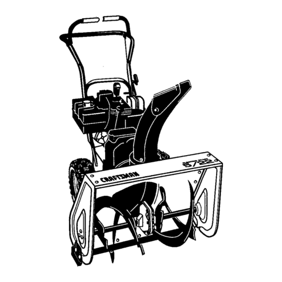
- Page 1 CRRFTSMRW 5 Horsepower 22 Inch Dual Stage 120V. Electric Start SNOWTHROWER MODEL NO. 536.886140 Caution: Read and follow all Safety Rules and Operating Instructions before first use , of this product. SEARS, ROEBUCK AND CO., Hoffman Estates, IL 60179 U.S.A. 760996 09/17/97...
- Page 2 LIMITED TWO-YEAR WARRANTY For two years from the date of purchase, when this Craftsman Snow Thrower is maintained, lubricated, and tuned up according to the operating and maintenance owner's manual, Craftsman will repair, free of charge, any defect in material or workmanship.
- Page 3 Disengage all clutches before starting the engine (motor). Do not operate the snow thrower without wearing adequate winter outer garments.Wear footwear that will improve footing on slippery surfaces. Handle fuel with care; it is highly flammable. Use an approved fuel container. Never remove fuel tank cap or add fuel to a running engine or hot engine.
-
Page 4: Content Of Parts Bag
17. Disengagepowertothe auger/impeller whensnowthroweris transportedor not in use. 18, Useonlyattachments andaccessories approved by the manufacturer o fthe snowthrower(suchas tire chains, electricstartkits,etc.). 19. Neveroperatethe snowthrower withoutgoodvisibilityor light.Always be sureof yourfooting,andkeepa firm holdonthe handles. W alk;never run. MAINTENANCE ANDSTORAGE 1. Check shear bolts and other bolts frequently for proper tightness to be sure the snow thrower is in safe... -
Page 5: Assembly
1- Screw, 5/16-18 x 2 In. Parts packed separately in carton (not shown full size) 2 - Ignition Keys (Attached to engine in plastic bag) 1 - container 5W30 oil CAUTION: Always wear safety glasses or eye shields while assembling snow thrower. - Page 6 TO REMOVE SNOW THROWER FROM CARTON • Locate and remove container of 5W30 oil. • Locate all parts packed separately and remove from the carton. NOTE: Place fuel stabilizer in a safe place until needed for storage. • Remove and discard the packing material from around the snow thrower.
- Page 7 Universaljoint Bracket TO INSTALL SHIFTER LEVER KNOB • Thread the 1/2-13 hexjam nut found in the parts bag onto shifter lever. Thread the shifter lever knob onto the threaded end of the shifter lever until it is snug against the hexjam nut and the lip is pointed away from the engine.
- Page 8 HOW TO SET UP YOUR SNOW THROWER • Your snow thrower is equipped with height adjust skids (see second figure on page 5) on the outside of the auger housing. To adjust the skid height for different conditions, (see To Adjust Skid Height paragraph on page 17).
-
Page 9: Components View
KNOW YOUR SNOW THROWER READ THIS OWNER'S MANUAL SNOW THROWER. Compare the illustrations yourself with the location of various controls and adjustments. Save this manual for future reference. Engine Engine Choke On Start Drive Clutch Auger Clutch IgniUon Control AND SAFETY RULES BEFORE with your SNOW THROWER Fast... -
Page 10: How To Use
Always wear safety glasses or eye shields while operating the snow thrower. We recommend standard safety glasses or a wide vision safety mask for over your glasses, available at Craftsman Retail Stores or Service Centers. CAUTION: Read owner's manual before operating machine. -
Page 11: Fill Oil/Gas
• For ease of maneuverability in light snow conditions, disconnect the klick pin from the wheel locked position and push into the single wheel drive (klick pin through axle hole only) position (see figure below). • Make sure that the klick pin is in the single wheel drive position of the axle only and not through the locked position. -
Page 12: Start/Stop Engine
Make sure to wipe up any spilled fuel be- fore starting the engine. Store gasoline in a clean, approved con- tainer and keep the cap in place on the container. TO STOP ENGINE • To stop engine, move the throttle control lever to O (STOP) position and remove key. - Page 13 COLD START • Be sure the auger drive and traction drive levers are in the disengaged (released) position. • Move the throttle control to '_ position. See figure on page 9 for loca- tion. • Remove the keys from the plastic bag. In- sert one key into the ignition slot.
-
Page 14: Specifications
snow blowing is accomplished when the snow is removed immediately after it falls. • For complete snow removal, slightly over- lap each path previously taken. Use more overlap in deep snow to prevent overloading. • The snow should be discharged down wind whenever possible. - Page 15 GENERALRECOMMENDATIONS The warranty on this snow thrower does not cover items that have been subjected to op- erator abuse or negligence. To receive full value from the warranty, the operator must maintain the snow thrower as instructed in this manual. The maintenance chart is pro- vided to assist the operator in properly maintaining the snow thrower.
- Page 16 LUBRICATION • Hex Shaft and Gears - Hex shaft and gears require no lubrication. All bearings and bushings are lifetime lubricated and require no maintenance. NOTE: Any greasing or oiling of the above components can cause contamination of the friction wheel. If the disc drive plate or friction wheel comes in contact with grease or oil, damage to the friction wheel will re- sult.
- Page 17 CAUTION: Always disconnect spark plug wire and tie back away from the plug before making any adjustments or repairs. TO ADJUST SKID HEIGHT This snow thrower is equipped with two height adjustment skids, located on the out- side of the auger housing (see figure be- low).
- Page 18 BELTS The drive belts on this snow thrower are of special construction and should be replaced with original equipment belts available from your nearest Craftsman Store or Service Center. You will need the assistance of a second parson while replacing the belts.
- Page 19 • Check clutch control cable adjustment, see page 17. • Reconnect spark plug wire. TRACTION DRIVE BELT If your snow thrower will not move forward, check the traction drive belt (see second figure on page 18) for wear (Check other causes also in the Trouble Shooting Points section).
- Page 20 If adjustment is necessary: • Loosen bolts in speed selector lever (see figure below). Speed Selector Lever TO REPLACE FRICTION WHEEL If the snoW thrower will not move forward, and the friction wheel is worn or damaged, you need to replace it as follows: (First allow the engine to cool).
- Page 21 If you think the engine-governed high speed needs adjusting, contact your nearest Craftsman Service Center, which has the proper equipment and experience to make any necessary adjustments, TO ADJUST...
- Page 22 NOTE: A yearly checkup or tune-up by a Craftsman Service Center is a good way to insure that your snow thrower will provide maximum performance for the next season.
- Page 23 Stop engine immediately and disconnect spark plug wire. Tighten all bolts and make all necessary repairs. If vibration continues, have the unit ser- viced by a Craftsman service repairman Replace drive belt Adjust traction drive cable Repair friction wheel Replace auger belt...
-
Page 24: Electric Start Assembly
CRAFTSMAN ELECTRIC START ASSEMBLY i¾. _ARTNO. PARTNAME ENGINE Model 143.985003 (See Engine pages) 710024 Screw, 5/16-18 120638 Washer, Hvsptlk Guide, Rod Belt RH 3949 120638 Washer, HvspUk Screw, 5116-24x.625 910828 Guide, Rod Belt LH 3949 120638 Washer, Hvsptlk 910828 Screw, 5/16-24x.625... - Page 25 CRAFTSMAN ® REF. PART NO. PART NAME 340578-833 Frame Assembly 780055 Screw, 5/16-18x.50 Tap. 583031-853 Panel, Bottom 310169 Screw, 1/4-20x.63 Tap. 761195 Plate, Clutch Arm Mtg. 761198 Arm-Clutch 710200 Bolt, 3/8-16 Shoulder ; 105 41529 Nut, 3/8-16 Hxctdkjam 340682 Clip, Cable...
- Page 26 CRAFTSMAN REF, PART NO. PART NAME 579941 Lever, Shaft Tract. Clutch 313853 Bearing, Flanged 137185 Cotter Pin .125xl.00 313919 Retum Spring 579937 Lever, SpringTrac CL 11871 Screw, 1/4-20x.63 782585 Nut, 1/4-20 Reghexctdk 583163-853 Disc, Assy Fric. Wheel 583206 Zer, Grease...
- Page 27 CRAFTSMAN REF. PART NO. PART NAME 10577 Gear Case, RH 10576 Gear Case, LH 710025 Screw, 1/4-20x.75 46931 Nut, 1/4-20 Mac-Lock 303008 Nut, 1/4-20 Hexkeps 9344 Screw, 3/8-16x.50 Tap. 9566 Oil Seal 50304 Bearing, Flanged 48275 Flatwasher .752xl .24x.093 340284...
- Page 28 CRAFTSMAN 22" - 5H.P. SNOW THROWER AUGER HOUSING ASSEMBLY PART NAME PART NO. 583124 Pulley, V4L Screw 5/16-18x.63 577400 71371 Square Key. 18Sqx.88Lg 334514 Spacer, Slev .676xlx.53 582960 Retainer, Ball 43846 Bearing, Ball 180077 Screw, 5/16-18x.75 710026 Nut, 5/16-18 Hexwdfllk 760811-833 Housing Assy.
- Page 29 CRAFTSMAN DISCHARGE CHUTE ASSEMBLY REF. PART NO. PART NAME 340720 Carr. Bolt5/16-18x.75 12021 Washer, Plastic 71038 Nut, 5/16-18 hexnylon 6711 PlasticWasher 12021 Plastic Washer Plastic Washer 6711 120393 Flatwasher .344x.69x.065 120638 Washer, Hvsptlk 120393 Flatwasher .344x.69x.065 13527 Knob, T 2 Blade...
- Page 30 CRAFTSMAN REF, PART NO. PART NAME 9552-853 Upper Handle 11234 Screw, 5/16-18x2.75 120393 Flatwasher .344x.69x.065 120638 Washer, HvspUk 120376 N_, 5/16-18 Reghex 11261 Stop, Red Pla_c 334195 Kit for RH Handle Assy 334195 Kit for LH Handle Assy. 4140 Pin, Clutch Handle...
- Page 31 CRAFTSMAN EF.I _O. ' PART NO. PART NAME Shaft, Axle Wheel/mid 580883 583012 Sprkt'& Hub Assy. Screw 14-20x2.25 73839 782585 Nut, "J/4-20Reghxctdk 581730 Bearing, Flanged 579857 Chain, Roller #42x40P 73840 Flatwasher .765x1.12x.06 ""_ ,, ,.'_.,j ... " _ 22" - 5H.P. SNOW THROWER WHEEL ASSEMBLY REF.
- Page 32 PART NAME 760971 Decal, 9" impeller 313892 Decal, Danger Chute 70141" Decal, Danger Auger 302922 Decal, Danger English 760972 Decal, Craftsman 760963 Decal, El Start 5/22 761079 Decal, Danger Chute 3902 Decal, Traction Dr. Engage 3903 Decal, Gear Selector 340047...
- Page 33 CRAFTSMAN 4-CYCLE ENGINE MODEL NUMBER 143.985003 CARBURETOR 640084 PART NAME REF. PART# 631615 THROTTLE SHAFT & LEVER ASSY. THROTTLE RETURN SPRING 331767 640070 THROTTLE SHU'I-I'ER 650506 THRO'I-I'LE & CHOKE SHUTTER SCREW 632108 631815 630735 631807 651025 630766 640018 640053 631951...
- Page 34 CRAFTSMAN 4-CYCLE ENGINE MODEE NUMBER 143.985003 >...
- Page 35 CRAFTSMAN 4-CYCLE ENGINE MODEL NUMBER 143.985Cq3 PART# I PART NAME 36469A CYLINDER INCL. 2,20,72&125) DOWEL P N _R727 OIL DRAIN EXTENSION _PxURCHASE LOCALLY) TENSION CAP 30969 WASHER 28277 GOVERNOR ROD 31334 GOVERNOR LEVER GOVERNOR LEVER CLAMP 31335 651018 SCREW, TORX T-15, 8-32X19/64"...
- Page 36 STARTER NO. 590742 REF. PART# 590742 590740 590616 590617 590645A 590647 590535 590574 590741 PART NAME STARTER, REWIND RETAINER DOG, STARTER SPRING, DOG PULLEY & REWIND SPRING ASSY IHOUSING ASSY, STARTER ROPE, STARTER (LENGTH 98"& 9/64"DIA.) HANDLE, STARTER LOCKING TAB...
- Page 37 CRAFTSMAN 4-CYCLE ENGINE MODEL NUMBER 143,985003 STARTER NO. 33290E REF. PART# 33290E 31749 33522 33769 33524 35911 35461 35450 35912 35452A 590500 33441 35453 35454 35462 35456 650819 32450B 650759 PART NAME ELECTRIC STARTER (110 VOLT) RETAINER RING SPRING RETAINER ANTI-DRIFT SPRING NUT &...
- Page 39 For the repair or replacement parts you need delivered directly to your home Call 7 am-7 pm, 7 days a week 1-800-366-PART (1-800-366-7278) Para ordenar piezas con entrega a domicilio -1-800-659-7084 For in-house major brand repair service Call 24 hours a day, 7 days a week 1-800-4-REPAIR (1-800-473-7247) Para pedir servicio de reparaci6n a...
Need help?
Do you have a question about the 536.88614 and is the answer not in the manual?
Questions and answers