Table of Contents
Advertisement
Available languages
Available languages
I (RRFTSMRN1
Operator's
Manual
Snow Thrower
9 Horsepower
Electric
Start
Dual
Stage
Model
536.887996
CAUTION: Before using this product,
read this manual and follow all of its
Safety Rules and Operating Instructions.
Manual del usario
Quitanieves
9 caballos
de fuerza
(hp)
Bietapico
Arranque
electrico
Modelo
536.887996
PRECAUCION:
Antes de usar este producto,
lea este manual y siga todas las reglas de
seguridad e instrucciones de operaci6n.
Sears, Roebuck
and Co., Hoffman
Estates,
IL 60179 U.S.A.
F-041084L
www.sears.com/craftsman
Advertisement
Table of Contents

Related Manuals for Craftsman 536.887996


Summary of Contents for Craftsman 536.887996
- Page 1 9 caballos de fuerza (hp) Bietapico Arranque electrico Modelo 536.887996 PRECAUCION: Antes de usar este producto, lea este manual y siga todas las reglas de seguridad e instrucciones de operaci6n. Sears, Roebuck and Co., Hoffman Estates, IL 60179 U.S.A. www.sears.com/craftsman F-041084L...
- Page 2 TWO-YEAR WARRANTY ON CRAFTSMAN SNOW THROWER For two years from the date of purchase, when this Craftsman Snow thrower is maintained, lubricated, and tuned up according to the operating and maintenance instructions in the owner's manual, Sears will repair, free of charge, any defect in material or workmanship.
-
Page 3: Training/Preparation
TRAINING Always wear safety glasses or eye shields during operation or while performing an ad- Read this operating and service instruction justment or repair to protect eyes from manual carefully. Be thoroughly familiar foreign objects that may be thrown from the with the controls and the proper use of the snow thrower. -
Page 4: Control And Operating Symbols
13. Never operate the snow thrower near e n- MAINTENANCE AND STORAGE closures, automobiles, window wells, drop- Check shear bolts and other bolts at fre- offs, and t he like without proper adjustment quent intervals for proper tightness to be ofthe snow d ischarge angle. - Page 5 Drive C lutch Forward ReverseAuger ClutchAuger Collector Engage Push ToEngage Fuel Fuel Oil M ixture Electric Starter Discharge DOWN Discharge Discharge LEFT Discharge RIGHT Weight Transfer Weight Transfer Transmission Ignition Key Lift Handle To Depress Pedal Insert To Run, Engage To Disengage Pull Out To Stop.
- Page 6 CONTENTS OF PARTS BAG (ACTUAL SIZE) 1 - Owner's Manual (not shown) 1 - Packet of Fuel Stabilizer (not shown) 1 - Warranty Card (not shown) foundin toolboxlocatedon beltcover *Non-Assembly Parts, *2- Shear Pins PARTS PACKED SEPARATELY IN CARTON (NOT SHOWN FULL SIZE) 2- Ignition Keys (Attached to engine in plastic bag) F-041084L...
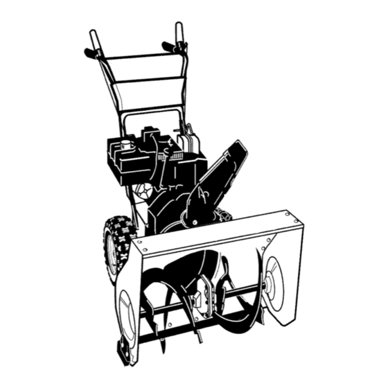
- Page 7 Figure 2 shows the snow thrower com- safety glasses or eye shields pletely assembled. ARNING: Always wear while assembling snow References to the right or left hand side thrower. of the snow thrower are from the view- point of the operator's position behind TOOLS...
- Page 8 TOASSEMBLE T HEHANDLE AND Install the fasteners that were re- CRANK ASSEMBLY moved in step 4. DO NOT tighten 1. Cut t ieholding s hift r odtolower until all bolts are in place. handle a nd move shifter tothefirst forward g ear. 2.
- Page 9 NOTE" I fthecables h ave become dis- connected, connect cables a sshown i n Figure 7 . Traction Drive Cable Auger Drive Cable Figure 7 HOW TO SET THE SKID HEIGHT Your snow thrower is equipped with height for different conditions, see To height adjust skids on the outside of the Adjuet Skid Height paragraph in the auger housing.
- Page 10 [o_o)_ KNOW YOUR SNOW THROWER READ THiS OWNER'S MANUAL AND SAFETY RULES BEFORE OPERATING YOUR SNOW THROWER. Compare the illustrations with your SNOW THROWER to familiarize yourself with the location of various controls and adjustments. Save this manual for future reference. Drive Lever Electric Auger...
- Page 11 [o_o)_ The operation of any snow thrower can the speed you desire by moving result in foreign objects being thrown speed shifter lever left into the ap- into the eyes, which can result in se- propriate notches on the shift lever vere eye damage.
- Page 12 [o_o)_ For ease of maneuverability in light 2. Remove the oil fill cap/dipstick. snow conditions, disconnect the Check the oil. klick pin from the wheel locked 3. If necessary, add oil until the oil position and push into the single reaches the FULL mark on the oil fill wheel drive position (unlocked axle...
- Page 13 [o_o)_ Fill the fuel tank only with a fresh, equipped with a three-wire clean, unleaded regular, unleaded pre- ARNING: The starter is mium, or reformulated automotive gas- power cord and plug and is oline. DO NOT use leaded gasoline. designed to operate on 120 volt AC Make sure that the container you pour household current.
- Page 14 [o_o)_ Push the primer button as speci- How To Start A Warm Engine fied below. Remove finger from If restarting a warm engine after a short primer button between pushes. shutdown, leave the choke lever in the off position and do not push the primer •...
- Page 15 [o_o)_ TO REMOVE SNOW FROM AUGER stick to remove snow from the auger housing. • Release auger drive lever. to remove snow or debris ARNING: Do not attempt • Move throttle lever to stop position. that may become lodged in •...
- Page 16 SERVICERECORDS Fill in dates as you Before Every Every Every completeregular Each Each Before SERVICE service. Often Hours Hours Hours Season Storage DATES Chain Lubrication Check Engine Oil Level • • • Change Engine Oil Check Spark Plug Remove Fuel Adjust Drive Belt * Adjust after 2 to 4 hours of use.
- Page 17 PRODUCT SPECIFICATIONS Chain HORSEPOWER 9 HP DISPLACEMENT 19.34cu.in. GASOLINE 4 quarts CAPACITY (unleaded) OIL CAPACITY 5W30 Hexshaft (20 oz capacity) Figure 13 SPARK PLUG: Champion RJ19LM (Gap .030 in.) or AUGER GEAR BOX equivalent The auger gear box is lubricated at the factory and should not require addition- VALVE CLEARANCE: Intake: .010 In.
- Page 18 NOTE: The oil will drain more freely S.A.E. 5W30 motor oi!, pouring when the engine is warm. slowly. DO NOT OVERFILL. 3. After draining all the oil, reinstall the "To Add Oil" in the Operation Sec- tion. oil drain plug securely. 4.
- Page 19 raise the adjustable skids. Tighten nect the spark plug wire and the mounting nuts. See Figure 16. ARNING: Always discon- place it where it cannot NOTE: For rocky or uneven surfaces, make contact with spark plug to pre- raise the front of the snow thrower by vent accidental starting when mak- moving the skids down.
- Page 20 BELT ADJUSTMENT Have someone engage auger drive Traction Drive Belt clutch. Check tension on belt (op- The traction drive belt has constant posite idler pulley). Belt should spring pressure and does not require flect about 1/2 inch (12.5 mm) with an adjustment.
-
Page 21: To Replace The Belts
HOW TO REPLACE THE BELTS two bolts. The auger housing and the motor box can now be split The drive belts are of special construc- apart for removal of the belt (see tion and must be replaced with original Figure 20). equipment replacement belts available from your nearest Sears service center. -
Page 22: To Remove Traction Drive Belt
Remove Bolts LoosenBolts iiiiiiii Motor Box Auger Housing Figure 20 Belt Guide Auger Drive Pulley Traction Drive Idler Auger Idler Pulley Auger Drive Belt Traction Drive Spring Traction Drive Belt E-Ring Traction Drive Pulley Swing Plate Engine Axle Rod Pulley Figure 21 F-041084L... - Page 23 How To Remove plate is properly secured (see The Traction Drive Belt Figure 22). If the snow thrower will not move for- ward, check the traction drive belt for wear or damage. If the traction drive belt is worn or damaged, replace belt as follows.
- Page 24 BELT GUIDE ADJUSTMENT "Z" Fitting Remove spark plug wire. Have someone engage auger drive. Measure the distance between belt guide and belt. The distance should be 1/8 inch (3.175 mm) for guide. See Figure Figure 24 Belt Guide ..i" 1/8 Inch - .i--\\ f (3.175 r am) The center of the "Z"...
- Page 25 TRACTION DRIVE CABLE ADJUSTMENT 7. Push the bottom of the traction Run the engine until the fuel tank is drive cable through the cable ad- empty and the engine stops. justment bracket until the "Z" Stand the snow thrower up on the hook can be removed.
-
Page 26: To Adjust Or Replace Friction Wheel
HOW TO ADJUST OR REPLACE 5. Install the bottom panel (see THE FRICTION WHEEL Figure 29). 6. Tighten the bolts on each side of the bottom panel. How To Check The Friction Wheel Bolt Bottom Panel If the snow thrower will not move for- ward, check the traction... - Page 27 How To Replace The Friction Wheel If the friction wheel is worn or damaged, the snow thrower will not move forward. The friction wheel must be replaced as follows. Run the engine until the fuel tank is Wheel Bo_om Panel empty and the engine stops.
- Page 28 11. Remove the three fasteners that 17. Check the adjustment of the friction hold the friction wheel to the hub wheel. See "How To Adjust The Friction Wheel" in this section. (see Figure 35). 18. Make sure the friction wheel and the 12.
- Page 29 HOW TO REPLACE Disconnect the spark plug wire. Make sure all moving parts have THE AUGER SHEAR BOLT stopped. The augers are secured to the auger Align the hole in the auger with the shaft with special shear bolts. These hole in the auger shaft.
- Page 30 If gasoline remains in the use fuel stabilizer supplied with unit tank, fumes may reach an open or purchase Craftsman Fuel Stabi- flame, spark or pilot light from a fur- lizer No. 3550. Add fuel stabilizer nace, water heater, clothes dryer, any gasoline left in the tank to mini- cigarette, etc.
- Page 31 h_o_U_oIo_ TROUBLE CAUSE CORRECTION Difficult starting Defective spark plug. Replace spark plug. Remove fuel from fuel tank. Water or dirt in fuel system. Add fresh fuel. Engine runs erratically Blocked fuel line, empty gas Clean fuel line; check fuel tank, or stale gasoline supply;...
- Page 32 SEARS, ROEBUCK AND CO. Federal and California Emission Control Systems Limited Warranty Small Off-Road Engines CALIFORNIA & US EPA EMISSION quired maintenance listed in your Owner's Manual, but Sears, Roebuck and Co. will not CONTROL WARRANTY STATEMENT deny warranty solely due to the lack of receipts The U.
- Page 33 ershall pay any charges formaking service Sears, Roebuck and 0o. according to Subsec- calls a nd/or fortransporting theproducts to tion 4 below. Any such part repaired or re- and from the place w here the inspection and/ placed under the ECS Warranty shall be orwarranty work i sperformed.
- Page 34 use shall not r educe Sears, Roebuck and Co. EMISSION-RELATED PARTS ECS Warranty obligations. INCLUDE FOLLOWING: 9.Unapproved add-on ormodified parts m ay 1. Carburetor Assembly and its Internal Com- not b eused t omodify orrepair aSears, Roe- ponents buck a nd Co. engine. Such u se voids this ECS a) Fuel filter Warranty and shall besufficient grounds for...
- Page 35 NOTES F-O41084L...
-
Page 36: Craftsman 9Hp Engine Exploded View
CRAFTSMAN 9HP SNOW THROWER 536.887996 ENGINE 25-3 25-2 Ref. Drive Page Ref. Auger Housing Page F-O41084L... - Page 37 CRAFTSMAN 9HP SNOW THROWER 536.887996 ENGINE Part No. Description 6219 CORD, STARTER 143.059013 ENGINE 002x97 BOLT, CARRIAGE 028x76 RETAINER, PUSH 710026 1501109 PULLEY, ENGINE 710247 WASHER 71063 WASHER .381D 71015 SCREW, 3/8-24X1.00 579932 BELT, V 3L 33.13LG 585416 BELT, V 4L 38.1MF16"...
- Page 38 CRAFTSMAN 9HP SNOW THROWER 536.887996 GEAR CASE Part Description Part Description 10577 CASE, GEAR, RH 50221 BRNG, FL 10576 CASE, GEAR, LH 1501191 SHAFT, INPUT SCREW 580295 710025 COLLAR, THRUST 15X143 454565 PIN, SPRING 9344 SCREW 48275 WASHER, FLAT 9566...
- Page 39 CRAFTSMAN 9HP SNOW THROWER 536.887996 FRAME Ref. Auger Housing Ref. Drive Page Part No. Description Part No. Description 1501055E701 COVER, BOTTOM 25x021 SCREW, TAP 310169 SCREW 50793 PULLEY, IDLER 1501226 YZ IDLER, AUGER NUT, JAM 3/8-16 711682 PIN, HAIR 1501052...
- Page 40 CRAFTSMAN 9HP SNOW THROWER 536.887996 DRIVE Ref. Shift Yoke Page Ref. Frame Page R/eL/@heel Ref. Page 201 _ Ref. Wheel Page F-041084L...
- Page 41 CRAFTSMAN 9HP SNOW THROWER 536.887996 DRIVE Description Part 1501092 LF AXLE, SWING PLATE YZ 579851 CHAIN, ROLLER #42x19.00 334163 BEARING AND RETAINER, ASSY WASHER 579858 25x020 SCREW, TAP 5/16-18x0.5 ASSY, HEX SHAFT 1501100 CHAIN, ROLLER #36x18.00 LG 579868 337029 BEARING, TRUNION CLUTCH R...
-
Page 42: Craftsman 9Hp Auger Housing Parts List & View
CRAFTSMAN 9HP SNOW THROWER 536.887996 AUGER HOUSING 526 525 Ref. Gear Case Page 542 540 F-O41084L... - Page 43 CRAFTSMAN 9HP SNOW THROWER 536.887996 AUGER HOUSING Key No. Part No. Description 1501211 PULLEY, V4L 8.4X .67 577400 SCREW, 5/16-18X.63 2001022 KEY, SQUARE 3/16 X 3/4 1501158 SPACER, FRICTION PULLEY 582957 YZ RETAINER, BALL BRNG 1501389 BEARING, BALL 001X92 BOLT, HEX 5/16-18 X 1/2...
- Page 44 CRAFTSMAN 9HP SNOW THROWER 536.887996 DISCHARGE CHUTE Ref. Auger Housing Page F-041084L...
- Page 45 CRAFTSMAN 9HP SNOW THROWER 536.887996 DISCHARGE CHUTE Key No. Part No. Description 2X100 BOLT, 5/16-18 X 1.00 CARG. 71071 WASHER, FLAT 15x144 NUT, 5/16-18 NYLOCK 71071 WASHER 1501260 KNOB, WING 3.00 002x97 BOLT, 5/16-18X1.125 762222 CHUTE ASSEMBLY 2X1 O0 BOLT...
- Page 46 CRAFTSMAN 9HP SNOW THROWER 536.887996 HANDLE . 746 720 724 727726"_/ 745 / 745 760 HDL105A F-041084L...
- Page 47 CRAFTSMAN 9HP SNOW THROWER 536.887996 HANDLE Key No, Part No. Description 1501205E701 HANDLE, UPPER LH 1501206E701 HANDLE, UPPER RH 11234 SCREW, 5/16-18X2.75 71071 WASHER, FLAT 71060 WASHER, SPTLK .31X.58X.08 15x144 NUT, 5/16-18 REGHEX YZ 11261 STOP, RED PLASTIC 337399 GRIP-HANDLE...
- Page 48 CRAFTSMAN 9HP SNOW THROWER 536.887996 CHUTE /" Ref. Handle Assy F-041084L...
- Page 49 CRAFTSMAN 9HP SNOW THROWER 536.887996 CHUTE Key No. Part No. Description 852-1 1501309 YZ ASSEMBLY, YOKE & ROD 852-2 313431 WASHER, CURVED SPRING 852-3 1501067 GEAR, CHUTE ROTATION 9T 852-5 579493 PIN, COTTER 852-6 1501306E701 BRACKET, GEAR MOUNT 852-7 1501293...
- Page 50 CRAFTSMAN 9HP SNOW THROWER 536.887996 SHIFT YOKE Part No, Key No, Description 336702E701 ROD, SHIFT 302628 SCREW, 1/4-20X.75 73826 NUT, 1/4-20 331624 KNOB, SLIP 760564 LEVER, SPRING 302628 SCREW, 1/4-20X.75 73826 NUT, 1/4-20 1501085 YZ ROD ASSY., SPEED SELECT 11X30...
- Page 51 CRAFTSMAN 9HP SNOW THROWER 536.887996 WHEELS 673 OJ Ref. Drive Page 653 _ Part Key No. Description 1501563 SHAFT, AXLE 1501089 SPRKT & HUB 01x193 SCREW, 1/4-20 x 1.75 15X145 NUT, 1/4-20 HEX NYLOCK YZ 1501114 BEARING, AXLE 712120 WASHER, FLAT...
- Page 52 CRAFTSMAN 9HP SNOW THROWER 536.887996 PANEL Key No. Part Description 1501203E201 PANEL 002x99 BOLT, CARRIAGE 71067 WASHER 15X145 NUT, 1/4-20 NYLOCK YZ DECALS Part No. Description DECAL DANGER CHUTE * 48x5580 48x5286 DECAL DANGER & FOOT * 48x5578 DECAL THROWN...
- Page 53 F-O41084L...
-
Page 54: Craftsman 4-Cycle Engine Parts List & View
CRAFTSMAN 4-CYCLE ENGINE MODEL NUMBER 143.059013 370C F-O41084L... - Page 55 CRAFTSMAN 4-CYCLE ENGINE MODEL NUMBER 143.059013 PART PART DESCRIPTION DESCRIPTION RPM High 3550 to 3750 33273A Blower Hsg Extension RPM Low 2000 650128 Screw, 10-24x 1/2" 35385 Cylinder (Incl. 2, 20 & 72) 37342 Cylinder Cover Gasket 27652 Dowel Pin...
- Page 56 MODEL NUMBER 143.059013 4-CYCLE ENGINE CRAFTSMAN 650836 Screw, 10-24 x 1/2" 30962 Fuel Line 27882 Valve Spring Cap 26460 Fuel Line Clamp 149A 35862 Valve Spring Cap 650665 Screw, 1/4-15 x 3/4" 27881 Valve Spring 34186A Fuel Tank Valve Spring Keeper (Incl.
- Page 57 CRAFTSMAN 4-CYCLE ENGINE MODEL NUMBER 143.059013 PART DESCRIPTION 590749 Rewind Starter 590599A Spring Pin (Incl. 4) 590600 Washer 590679 Retainer 590601 Washer 590678 Brake Spring 590680 Starter Dog 590412 Dog Spring 590682 Pulley & Rewind Spring Assembly 590750A Starter Housing Assembly 590535 Starter Rope (Length 98"...
- Page 58 CRAFTSMAN 4-CYCLE ENGINE MODEL NUMBER 143.059013 40/1_ F-O41084L...
- Page 59 CRAFTSMAN 4-CYCLE ENGINE MODEL NUMBER 143.059013 PART DESCRIPTION 640052 Carburetor (Inc1.184 of Engine Parts List) 631776A Throttle Shaft & Lever Assembly 631970 Throttle Return Spring 631778 Throttle Shutter 650506 Shutter Screw 632112 Choke Shaft & Lever Assembly 632174 Choke Shutter...
- Page 60 CRAFTSMAN 4-CYCLE ENGINE MODEL NUMBER 143.059013 F-O41084L...
- Page 61 CRAFTSMAN 4-CYCLE ENGINE MODEL NUMBER 143.059013 PART DESCRIPTION 33329E Electric Starter (110 Volt) 33451 Dust Cover 33842 Retainer Ring 33430 Spring Retainer 33431 Anti-drift Spring 37050 Gear & Nut (Incl. 2) 35449 Drive End Cap Ass'y. (Incl. 7) 35450 "O" Ring...
- Page 62 TABLADE LOCA, L IZACIONY SIMBOLOS INTERNACIONALES..REPARAClON DE AVERIAS ..ENSAMBLAJE....PEDIDODE PIEZAS/SERVICIO ..GARANTIA LIMITADA DE DOS AI_IOS PARA EL QUITANIEVES CRAFTSMAN Durante dos ahos a partir de la fecha de compra, siempre que a este quitanieves Craftsman se le de mantenimiento,...
- Page 63 CAPACITACION y/o del sol hace que el combustible se expanda. Lea con atenci6n las instrucciones en el manual de operaci6n y servicio. Familiar? Para todos los quitanieves con motores cese completamente con los controles y de arranque el6ctrico, use cables de ex- el uso apropiado del quitanieves.
- Page 64 8. Cuando limpie, repare oinspeccione ruedas, juegos dearranque el6ctrico, quitanieves, asegOrese deque labarre- etc.). na/propulsor ytodas las partes m6viles 19.Nunca opere e lquitanieves sin tener bue- seencuentren detenidas, yque todos los navisibilidad oiluminaci6n. Asegt_rese controles esten desenganchados. Desco- siempre que tiene b uena estabilidad, necte e lcable d elabujia y mant6ngalo sujete con firmeza elmango.
- Page 65 [.,,._o)nUCo_ IMPORTANTE: Muchos de estos simbolos estan colocados en su quitanieves o est_m impresos en los manuales que vienen con el producto. Antes de operar el quitanieves aprenda y comprenda objetivo de cada sfmbolo. SiMBOLOS DE CONTROL OPERACI6N Despacio Rapido Arranque electrico Arranque de motor Motor en marcha...
- Page 66 SiMBOLOS DE CONTROL Y OPERACION Mezcla de combustible Combustible Aceite y aceite Descarga hacia Descarga hacia Oescarga hacia la Descarga hacia la ABAJO ARRIBA IZQUIERDA DERECHA Transferencia de peso Transferencia de peso Llave de encendido Levants st mango Presione el pedal Insertar para marcha, para enganchar, para desenganchar.
- Page 67 CONTENIDO DE LA BOLSA DE PARTES (TAMAI_IO REAL) 1 - Manual del Propietario (no se muestra) 1 - Paquete de estabilizador de combustible (no se muestra) 1 - Tarjeta de garantia (no se muestra) *Las partesque no necesitanensambladose encuentranen la caja de herramientasubicadaen la cubierta de la correa.
- Page 68 La Figura 39 muestra el quitanieves gafas de seguridad o protecto- completamente ensamblado. ADVERTENCIA: Siempre use res para los ojos mientras en- La referencia a los lados izquierdo sambla el quitanieves. derecho del quitanieves se hace desde la posici6n del operador cuando 6ste se HERRAMIENTAS...
- Page 69 COMO ENSAMBLAR EL MANGO Y Palanca EL CON JUNTO DE LA MANIVELA Conexi6n en "Z" Corte los amarres que sujetan palanca de cambios al mango inferior y mueva la palanca a la primera velocidad de avance. Corte y deseche el amarre de pl_ts- tico que sujeta e! conjunto...
- Page 70 Cable de NOTA" Si los cables se han desconec- Cable de propul- propulsi6n si6n de la barrena tado, conectelos come se muestra en la Figura Figura 44 C6MO AJUSTAR LOS PATINES DE ALTURA Su quitanieves est& equipado con patines de clones, consulte "Ajuste de los patines altura", en la secci6n de Servicio...
- Page 71 CONOZCA SU QUITANIEVES LEA ESTE MANUAL DEL USUARIO Y LAS REGLAS DE SEGURIDAD ANTES DE USAR USAR SU QUITANIEVES. Compare las figuras con su QUITANIEVES para familarizarse con las posiciones de los diversos controles y ajustes, Guarde este manual para referencia futura. Palanca de Palanca de propul- Bot6n de arran-...
- Page 72 Laoperaci6n decualquier quitanieves puede ca de cambio de velocidades a la ranura ocasionar que objetos extrafios sean l anza- apropiada del panel de control de cam- dos con fuerza hacia l os ojos, Iocual podria bios. resultar enlesiones graves. Use siempre Velocidad 1,2 - Nieve mojada, pesada gafas deseguridad oprotectores...
- Page 73 Pasador klick Tapa/varilla indicadora I nivel de ace_te Posici6n desenganc Tracsi6n sola rueda Figura 48 NOTA: El nivel del aceite deber_t estar entre la marca FULL (lleno) y la marca NOTA: AsegOrese de que el pasador klick est6 en la posici6n de tracci6n de una sola ADD (agregar) Figura 49 rueda en el eje solamente,...
- Page 74 Uene e ltanque solamente con gasolina fres- ca, l impia, regular sin plomo, sOper sinplo- arranque esta equipado con un DVERTENCIA: El motor de moo gasolina automotor reformulada. cable de alimentaci6n y enchu- use gasolina con plomo. AsegOrese deque fe trifilar, disehados para funcionar elrecipiente que contiene lagasolina...
- Page 75 tomacorrientes trifilar de120 voltios CA, Cbmohacerarrancarun motorcaliente conectado atierra. Si esta arrancando un motor caliente des- 6. Empuje elboron o ebador delamanera pu6s de haberlo apagado por un periodo indicada acontinuaci6n. Quite e ldedo corto, deje la palanca del estrangulador en la del bot6n c ebador entre c ebados.
- Page 76 COMO QUITAR LA NIEVE Y lice el bast6n de limpieza para quitar la nieve ESCOMBROS ATASCADOS atascada en el alojamiento de la barrena. LA BARRENA Suelte la palanca de propulsi6n de la ba- rrena. Mueva la palanca de control de acelera- ci6n a la posici6n "parar".
- Page 77 H-' h, h, H h, o] REGISTROSDE SERVICIO Anote lasfechas a me- Antes Cada Cada Cada Cada Antes FECHA didaquecompletael de ca- menu- tempo, servicio da uso horas horas horas rada guardar SERVICIO Correa de pr0puisi6n de la barreRa ..Lubricaci6n de la cade- Revisar el nivei de acei-...
- Page 78 u-' h, h, u h, o] ESPEClFICAClONES PRECAUCION: No permita que la grasa entre en contacto con la rueda de friccion ni con la placa del disco de propulsion. CABALLOS DE 9 HP FUERZA 6. Instale el panel inferior. CILINDRADA 19.34cu.in Cadena CAPACIDAD DE...
- Page 79 L_-' h, h, u h, o] CAMBIO DE ACEITE NOTA: El aceite fluir& mejor si el motor es- t,. caliente. Una vez que haya sacado todo el aceite, 1. Coloque el quitanieves de manera tal que coloque nuevamente el tap6n de drenaje el tap6n de drenaje del aceite sea el pun- en su lugar y aprietelo para que quede to m_.s bajo del motor.
- Page 80 4. Afloje las tuercas de montaje que sujetan los patines de ajuste de altura. Para bajar la parte delantera del quitanieves, suba el arranque accidental del mo- ADVERTENCIA: Para prevenir los patines. Apriete las tuercas de mon- tor, siempre desconecte el ca- taje.
- Page 81 _o][o] i'd P'i_llllI_"_ AJUSTE DE LAS CORREAS beria ceder media pulgada (12,5 mm) con presi6n moderada Correa de propulsion (Figura 55). Puede que tenga La correa de propulsi6n tiene mover la polea guia mas de una presi6n de resorte constante y no re- vez para conseguir la tensi6n...
- Page 82 _o][o] h,*d P 'i_llllI_"_ 2. Afloje los pernos a cada lade del la correa del propulsor de la bar- panel inferior (Figura 56). rena por una correa de repuesto original de fAbrica disponible en un 3. Quite el panel inferior. centro de servicio autorizado (Figura 58).
- Page 83 _o,][o] h,'d P'i_llllI_"_ Retire Oaja del AIojamiento motor de la barrena Figura 57 /Correa de propulsi6n Polea del motor Guia de la correa Polea de propulsi6n de la barrena Polea guia de la barrena Correa de propulsi6n de la barrena Resorte de propulsi6n Oorrea de...
- Page 84 _o][o] h,'d P'i_llllI_"_ Como desmontar la correa de sujeta (Figura 59). propulsion Si el quitanieves no se mueve hacia adelante, asegOrese de que la correa de propulsi6n no est6 excesivamente desgastada o dar_ada. Si Io est,_, reemplAcela de la siguiente manera.
- Page 85 _.-]=_v_[o][o] i'd V_ILII[-'_. AJUSTES DE LA CORREA GUiA Acceserie "Z" Quite el cable de la bujia. Pida a alguien que ponga el propul- sor de la barrena. Mida la distancia entre la gufa de la correa y la correa. La distancia be ser de 1/8 de pulgada (3,175 mm) para la gufa.
- Page 86 _o][o] h,'d P'i_llllI_"_ AJUSTES DEL CABLE DE PROPULSION Deje el motor en marcha hasta que Meta la parte inferior del cable de el tanque de combustible quede propulsibn por el soporte de ajus- cioy el motor se pare. te del cable hasta que pueda sacar Levante...
- Page 87 _o][o] h,'d P'i_llllI_"_ C6MO AJUSTAR O REEMPLAZAR LA RUEDA DE FRICCI6N Como revisar la rueda de friccion 12 y 13 pulgs. 4-1/8" 16 pulgs. 4-5/16" Si el quitanieves no avanza, revise la Si la rueda de fricci6n no esta en la correa de propulsi6n per tracci6n, el ca- posici6n correcta,...
- Page 88 _o][o] h,'d P'i_llllI_"_ Como reemplazar la rueda de friccion Perno Si la rueda de fricci6n esta gastada dar_ada, el quitanieves no avanza. rueda de fricci6n se debe cambiar de la siguiente manera. Panel inferior Llanta Deje el motor en marcha hasta que el tanque de combustible...
- Page 89 _o][o] h,'d P'i_llllI_"_ 12. Quite la rueda de friccion del cu- 18. Aseg6rese de que la rueda de fric- bo. Deslice la rueda de friccion ci6n y la placa del propulsor de dis- fuera del eje hexagonal. co no tienen ni grasa ni aceite.
- Page 90 _o,][o] h,'d P'i_llllI_"_ COMO REEMPLAZAR ci6n de parada. Desenganche todos los controles. PERNOS DE SEGURIDAD Desconecte el cable de la bujia. Aseg0- LA BARRENA rese de que todas las piezas m6viles se Las barrenas est_.n sujetas al eje de la ba- hayan detenido.
- Page 91 Craftsman de una caldera, calentador NOm. 3550. Armada el estabilizador agua, 8ecadora de ropa, cigarrillo, de combustible a cualquier cantidad etc.
- Page 92 PROBLEMA CAUSA CORRECClON Dificultad Bujia defectuosa. Reemplace la bujia defectuosa. arranque Agua o suciedad en el sistema Saque el combustible del tanque. de combustible. Ahada combustible fresco. El motor funeiona Linea de combustible bloqueada, Limpie la linea de combustible; erraticamente falta de combustible o mezcla de revise la existencia de combustible...
- Page 93 SEARS, ROEBUCK AND CO. Garantia limitada de cumplimiento con el Sistema Federal de control de emisiones y con el sistema de control de emisiones Estado de California pequeSos Motores para vehiculos todo terreno CONTROl- DE EMISIONES SISTEMA PARA EL CONTROl- CAMFORNIA Y DE l,A AGENCIA EMISIONES...
- Page 94 Sears, Roebuck and Co., o a Sears, Roebuck A. CAMPO DE APLICACION: Esta garantia and Co., al 1-800-473-7247 (llamada gratui- deberR aplicarse a los motores pequefios para vehiculos todo terreno modelo 1995 y mode- ta en E.U.A.). los de aries posteriores en California (para otros estados, motores modelo 1997 y mode-...
- Page 95 Garantia SOE d ebera garantizarse por e lresto aprobada por S ears, Roebuck and Co. p ara del P eriodo delamisma. utilizarse en eldesempefio decualquier man- tenimiento ocambio delaGarantia SCE, la 3.Cualquier parte g arantizada yrelacionada cual se proporcionara sin cargo alguno para e l con emisiones que seespecifique para c am-...
- Page 96 Your Home .._i_i!iii_ii_ii iiiiiiiiiiiiiiiljj ¸_¸ For repair - in your home - of all major brand appliances, iiiiiiiiiiiiiiii_i_ iiiiiiiiiiiiiiii' lawn and garden equipment, or heating and cooling systems, iiiiiiiiiiiiiiii no matter who made it, no matter who sold it! iiiiiiiiiiiiiiii iiiiii iiiiiiiiiiiiiiii...