Table of Contents
Advertisement
Quick Links
Advertisement
Table of Contents

Related Manuals for All-Power APG3201


Summary of Contents for All-Power APG3201
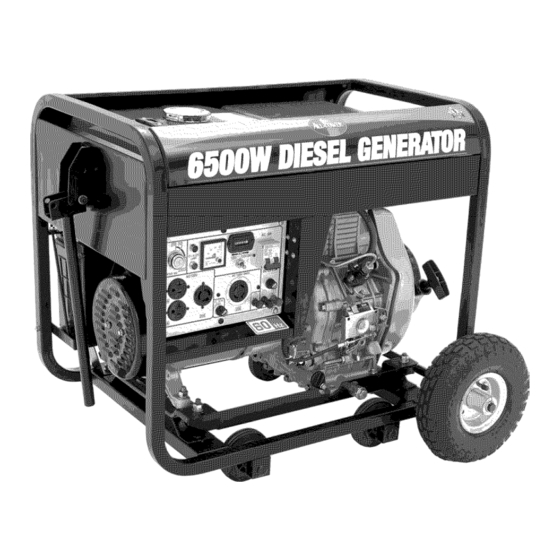
- Page 1 6500WATT A IR-COOLED DIESEL GENERATOR...
-
Page 2: Table Of Contents
AIR-COOLED DIESEL GENERATOR TABLE OF CONTENTS Page number Chapter 1 Technical Specifications and Data .......... 3 1-1 Technical specifications and data ..........3 1-2 Basic operating instruction,s............1-3 General dimensions and overview of generator ....5 Chapter 2 Operating the Diesel Generator..........7 2-1 Main points of safety during operation of the generator .. -
Page 3: Technical Specifications And Data
AIR-COOLED DIESEL GENERATOR CHAPTER 1. TECHNICAL SPECIFICATIONS DATA Technical specifications and data CHANGFA Single-cylinder diesel generator CFA6500CL_E_/CF CFA6500CL_E_S A6500CX_E_ /CFA6500CX_E_S Rated frequency (Hz) 220_230_240_110 /220_115/230_120/2 380/220_400/230_420/240 Rated voltage Rated output power (kVA) output power (kVA) Rated rotation speed 3600 3600 (rpm) Power factor... - Page 4 OWNER'S MANUAL C: recoil starter C: recoil starter Starter system E: recoil starter/electric E: recoil starter/electric starter (summer),_l (summer),_10# (winter), Fuel type (winter), _35#(chill _35#(chill cold) diesel cold) diesel Lube oil SAE 15W 40 SAE 15W 40 L_X:CFA186F L_X3:CFA186F Engine model E:CFA186FE E3:CFA186FE Single-cylinder,4-...
-
Page 5: Basic Operating Instruction,S
OWNER'S MANUAL Basic operating instructions 1-2.1 Under the given conditions, the generator will output the specified power in the table listed below. Table Height above sea level (ft) Ambient temperature (F) +60 (+20 C) 1-2.1 Under the given conditions, the generator will output the approximate power in the table listed below. - Page 6 OWNER'S MANUAL CHAPTER 2 OPERATING THE DIESEL GENERATOR 2-1 General main points of safety during operation of the generator set. In order to operate the generator set safely, please follow all the instructions provided in this manual carefully. Doing so otherwise may lead to accidents and or equipment damage.
- Page 7 OWNER'S MANUAL Note: When connecting devices to the generator, make sure all other devices rated lower than the generators output. generator socket should not be overloaded over its regulated limit 2-1.5 Other safety points Before operating this generator, all operators should have a good knowledge of how to break the circuit if any accidents...
-
Page 8: Preparation Before Operation
OWNER'S MANUAL 2-2 Preparation before operation 2-2.1 Fuel choices and fuel treatment Fuel tank Use only light diesel fuel. The fuel should be filtered clean. Never let dust water mix with fuel in the fuel tank. Otherwise it will clog the fuel lines and oil nozzles. - Page 9 OWNER'S MANUAL 2-2.2 Filling engine Remove the dipstick from the engine Make sure the generator is on level ground, and fill the engine with 15W40 engine oil. Put the dipstick back into the hole to check the engine oil level. it(H) _t(L) _8_ii'_...
-
Page 10: Checking The Operation Of The Diesel Engine
OWNER'S MANUAL 2-2.3 Checking the air filter (1) Loosen the butterfly nut, take the cover of the air filter off and take the air filter element out. Do not wash the air filter element. When the performance of the engine decreases when the color of the exhaust gases is bad, exchange fiRer core... -
Page 11: Starting The Generator
OWNER'S MANUAL 2-3.3 Engine break in When you purchase a brand new engine, the engine must be properly broken in. The break in period is about 20 hours. (1) Avoid overloading the engine when brand new (2) Change the engine oil according to specifications. - Page 12 OWNER'S MANUAL The electromagnetic iron will be triggered, now turn it clockwise to the "START" position. 4. After the diesel engine is started, remove your hand from the switch handle; switch will automatically reset itself to the "ON" position. 5. If the engine is not starting after 10 seconds...
-
Page 13: Procedures For Starting The Generator
OWNER'S MANUAL 2-5 Procedures for starting the generator This procedure applies to the CF series recoil starting style models. Open the fuel valve I... - Page 14 OWNER'S MANUAL...
-
Page 15: Proper Operation Of The Generator
OWNER'S MANUAL 2-6 Proper operation of the generator 2-6.1 Operating the diesel engine 1. Pre-heat the diesel engine for 3 minutes under no load conditions. First check the height of the lubricating oil level, if it is Fuel adjustment bolt SD:ed handle low, refill it. - Page 16 OWNER'S MANUAL Connect the large loads onto the generator first. If everything is functional, smaller loads can then be added. If the generator shuts off, it may be because the load being drawn by all the various devices are too high. In this event, decrease the number of small devices until everything is functional.
-
Page 17: Stopping The Generator
OWNER'S MANUAL 2-8 Stopping the generator 1. Take the electrical load of f the generator 2. Put the speed handle in the "RUN" position and let the engine run for 3 minutes after unloading. Do not stop the engine immediately let it warm down. -
Page 18: Chapter 3 Maintenance
OWNER'S MANUAL CHAPTER 3 MAINTENANCE 3-1 Maintenance schedules Keeping your generator well maintained will prolong the life of your generator. Everything needs to be checked including the diesel engine, generator, control cabinet, frame. Betbre starting the maintenance, make sure the diesel engine is off: Please refer to the Table 3-1 for the proper maintenance schedule. - Page 19 OWNER'S MANUAL 3-1.1 Changing the engine oil (every 200 hours) Take the oil cover off. Remove the oil drain plug when the diesel engine is still hot. Be careful of hot oil and hot engine as you may get burned. The bolt located at the bottom...
- Page 20 OWNER'S MANUAL 3-1.5 Battery check Make sure the battery acid is full. The engine uses a 12V battery. Due to numerous starting cycles, the battery acid may be used up. Also, before filling, verify that the battery is not damaged in any way.
- Page 21 OWNER'S MANUAL 4-1 Questions and doubts If you do not understand anything or have any questions, please feel free to contact your local dealer or with our company directly. Below is a list of some information you should have ready before contacting your local dealer or us. 1.
- Page 22 OWNER'S MANUAL CHAPTER 5 GENERATOR PARTS DIAGRAMS LISTINGS Figure 5-1. Overall view of engine generator assembly Table 5-1. Please refer to figure 5-1for illustration Number Part Number Part Description Quantity CFA6500CXE1 CFeries diesel engine Starter Motor CFA6500CXE2 CFA6500CXE3 Flywheel generator Bolt CFA6500CXE4 CFA6500CXE5...
- Page 23 OWNER'S MANUAL Figure 5-2. Exploded view of frame assembly Table 5-2. Please refer to figure 5-2. Number Part Description Quantity Part Number (CFA6500CXE) M6 x 25 Bolt CFA6500CXE17 M6 Flat washer CFA6500CXE18 Shock absorber CFA6500CXE19 Washer CFA6500CXE20 M6 Nut CFA6500CXE21 CFA6500CXE22 Engine cover Rubber cover...
- Page 24 OWNER'S MANUAL CFA6500CXE33 Battery M8x12 bolts CFA6500CXE34 Rubber absorber CFA6500CXE35 Motor mount CFA6500CXE36 CFA6500CXE37 Battery tray M6 Nut CFA6500CXE38 CFA6500CXE39 Spring washer 6 M6 x 35 Bolt CFA6500CXE40 M10 Nut CFA6500CXE41 CFA6500CXE42 Spring washer Flat washer CFA6500CXE43 M10 x 20 CFA6500CXE44 Bracket CFA6500CXE45...
- Page 25 OWNER'S MANUAL Figure 5-3. Electric panel parts drawing Table 5-3. Please refer to Figure Part Number Number Part Description Quantity (CFA6500CXE) CFA6500CXE69 Positive DC port CFA6500CXE70 Negative DC port Grounded bolt CFA6500CXE71 Bolt CFA6500CXE72 CFA6500CXE73 Large Nut Bolt CFA6500CXE74 Bolt CFA6500CXE75 CFA6500CXE76 Large Nut...
- Page 26 OWNER'S MANUAL Hour meter CFA6500CXE85 Hour meter bolts CFA6500CXE86 DC Fuse CFA6500CXE87 Voltmeter CFA6500CXE88 CFA6500CXE89 CFA6500CXE90 4 prong socket Breaker bracket CFA6500CXE91 CFA6500CXE92 Breaker CFA6500CXE93 CFA6500CXE94 Wiring harness Electrical CFA6500CXE95 Figure 5-4. Generator head assembly Table 5-4. Please refer to figure Number Part Description...
- Page 27 OWNER'S MANUAL Figure 5-5. Fuel system components Table 5-5. Please refer to figure 5-5. Number Part 'Description Part Number (CFA6500CXE) Quantity CFA6500CXE Fuel Cap Seal CFA6500CXE112 CFA6500CXE113 Filtering M5 x 10 screw CFA6500CXE114 Fuel lever indicator CFA6500CXE M6 x 25 Bolt CFA6500CXE116 CFA6500CXE117 Large...
- Page 28 OWNER'S MANUAL CFA6500CXE127 Wing nut Fuel line CFA6500CXE128 CFA6500CXE129 Fuel inlet pipe CFA6500CXE130 High pressure fuel pump CFA6500CXE High pressure fuel pipe CFA6500CXE132 Fuel injector Overfill tube CFA6500CXE133 CFA6500CXE134 Fuel overfill pipe...
-
Page 29: Limited Warranty
OWNER'S MANUAL Limited Warranty All-Power America warrants to the original purchaser who uses the product in a consumer application (personal, residential or household usage) that all products covered under this Warranty are free from defects in material and workmanship one year from the date of purchase. All products covered by this limited Warranty... - Page 30 OWNER'S MANUAL Limited Warranty (cont'd) THIS WARRANTY DOES COVER: Merchandise sold as reconditioned, used as rental equipment, or floor display models. Merchandise that has become damaged or inoperative because of ordinary wear, misuse, cold, heat, rain, excessive humidity, freeze damage, use of improper chemicals,...
Need help?
Do you have a question about the APG3201 and is the answer not in the manual?
Questions and answers