Table of Contents

Related Manuals for Vulcan-Hart GPO72 ML-114737


Summary of Contents for Vulcan-Hart GPO72 ML-114737
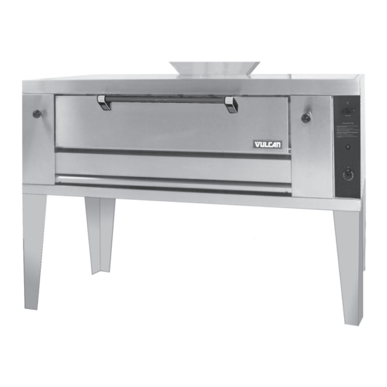
- Page 1 INSTALLATION & OPERATION MANUAL GPO72 GAS PIZZA OVEN MODEL GPO72 ML-114737 Model GPO72 V U L C A N C O M P A N Y , P . O . B O X 6 9 6 , L O U I S V I L L E , 4 0 2 0 1 - 0 6 9 6 , TEL.
-
Page 2: Important For Your Safety
CAUSE PROPERTY DAMAGE, INJURY OR DEATH. READ THE INSTALLATION, OPERATING AND MAINTENANCE INSTRUCTIONS THOROUGHLY BEFORE INSTALLING OR SERVICING THIS EQUIPMENT. IN THE EVENT OF A POWER FAILURE, DO NOT ATTEMPT TO OPERATE THIS DEVICE. — 2 — © VULCAN COMPANY, 1997... -
Page 3: Table Of Contents
TABLE OF CONTENTS GENERAL............... 4 INSTALLATION . -
Page 4: General
PLEASE KEEP THIS MANUAL FOR FUTURE USE GENERAL Vulcan pizza ovens are produced with quality workmanship and material. Proper installation, usage and maintenance of your pizza oven will result in many years of satisfactory performance. It is suggested that you thoroughly read this entire manual and carefully follow all of the instructions provided. -
Page 5: Installation Codes And Standards
The installation location must allow adequate clearances for servicing and proper operation. A minimum front clearance of 48" is required. Do not obstruct the flow of combustion and ventilation air. Adequate clearance for air openings into the combustion chamber must be provided. Make sure there is an adequate supply of air in the room to replace air taken out by the ventilating system. - Page 6 Left Deck Center Deck Right Deck P L - 5 2 6 1 7 Fig. 1 Flue Deflector Install the flue deflector. The hardware is provided with the pressure regulator inside the oven. To install, slide the front lip of the flue deflector under the two clips attached to the top of the oven. Then bring back to the rear.
-
Page 7: Leveling
Assembling Stacked Ovens 1. Install the 17" legs on the lower oven and position the lower oven as near to its final location as possible. (For conversion: Legs must be changed to short legs provided in the conversion package. Discard the longer legs.) 2. - Page 8 Optional Electrical Connection Pressure Regulator Gas Valve P L - 5 2 6 2 0 Fig. 4 Install the gas pressure regulator. Natural gas pressure regulators are preset for 3.7" W.C. (Water Column); propane gas pressure regulators are preset for 10" W.C. When connecting fittings to the rear inlet pipe projecting through the body back of the oven, hold back on this pipe with a wrench to eliminate any excess strain on the internal oven piping.
-
Page 9: Testing The Gas Supply System
TESTING THE GAS SUPPLY SYSTEM When gas supply pressure exceeds psig (3.45 kPa), the oven and its individual shutoff valve must be disconnected from the gas supply piping system. When gas supply pressure is psig (3.45 kPa) or less, the oven should be isolated from the gas supply system by closing its individual manual shutoff valve. -
Page 10: Adjustments
ADJUSTMENTS All pilot lighting adjustments must be performed by a qualified installation or service person. Pilot Burner 1. Remove the thermostat dial, the adjustable baffle knob, and the lower front panel cover. 2. Rotate the adjustment screw (Fig. 5) clockwise to decrease the pilot, or counterclockwise to increase the pilot flame. - Page 11 Air Supply 1. Remove the lower front panel cover. 2. Turn thermostat dial to a mid-range temperature. 3. Adjust the air shutters (Fig. 6) until the flame is sharp but not lifting off the burner. Air Shutters P L -5 2 6 2 2 Fig.
-
Page 12: Operation
OPERATION WARNING: THE OVEN AND ITS PARTS ARE HOT. USE CARE WHEN OPERATING AND CLEANING THE OVEN. CONTROLS (Fig. 7) Thermostat — Regulates gas flow to the burners to maintain set temperature. Temperature range for the standard oven is 300-650°F; temperature range for the optional 115 Volt control is 300-700°F. -
Page 13: Lighting Instructions
LIGHTING INSTRUCTIONS 1. Remove lower front panel of the oven by pulling straight out. 2. If the pilot is out, turn the thermostat dial to the OFF position. Wait 5 minutes before relighting. 3. The gas valve knob must be in the ON position. 4. - Page 14 Stubborn spots or stains that resist soap and water usually can be removed with a paste of water and a mild scouring powder. When applying these powders, be sure to rub in the direction of the polish lines on the stainless steel to preserve the original finish. Fingerprints are sometimes a problem on highly polished surfaces of stainless steel.
-
Page 15: Maintenance
To obtain service and parts information concerning this oven, contact the Vulcan Service Agency in your area (refer to listing supplied with the oven), or Vulcan Company Service Department at the address or phone number shown on the front cover of this manual. -
Page 16: Troubleshooting
3. Problem with pilot outage gas shutoff valve. 4. Draft. Poor Ignition 1. Insufficient input. 2. Poor air-gas adjustment (contact your local Vulcan Service Office). 3. Restriction in pilot orifice. 4. Restriction in main burner ignition ports. FORM 31018 (2-97) PRINTED IN U.S.A.
Need help?
Do you have a question about the GPO72 ML-114737 and is the answer not in the manual?
Questions and answers