Table of Contents
Advertisement
Quick Links
Operation and Instruction Manual
T
ABLE OF
Introduction . . . . . . . . . . . . . . . . . . . . . . . . .2
User Replaceable Parts . . . . . . . . . . . . . . .3
Warning Labels . . . . . . . . . . . . . . . . . . . . . .4
Installation . . . . . . . . . . . . . . . . . . . . . . . . .5
How to Dispense a Cup of Coffee . . . . . . . . . .7
User Programming Instructions . . . . . . . . .8
Engineer Program Settings . . . . . . . . . . . .9
Cleaning Instructions . . . . . . . . . . . . . . . . 14
Troubleshooting Guide . . . . . . . . . . . . . . .16
Wiring Diagram . . . . . . . . . . . . . . . . . . . . .19
Prior authorization must be obtained from
Grindmaster Corporation for all warranty claims.
© Grindmaster Corporation, 2009
Printed in USA
GRINDMASTER CORPORATION
Liquid Coffee Dispenser
LCD-2A
& LCD-2R
C
ONTENTS
for
(Ambient Cabinet)
(Refrigerated Cabinet)
Grindmaster Corporation™
4003 Collins Lane
Louisville, Kentucky 40245
(502) 425-4776 800-695-4500
(800) 568-5715 (technical service only)
FAX (502) 425-4664
www.grindmaster.com
™
Models LCD-2A and LCD-2R
0910 Form # AM-328-04
Part # 63543
Advertisement
Table of Contents

Subscribe to Our Youtube Channel
Related Manuals for Grindmaster LCD-2A


Summary of Contents for Grindmaster LCD-2A
-
Page 1: Table Of Contents
Wiring Diagram .....19 Prior authorization must be obtained from Models LCD-2A and LCD-2R Grindmaster Corporation for all warranty claims. Grindmaster Corporation™ 4003 Collins Lane... -
Page 2: Introduction
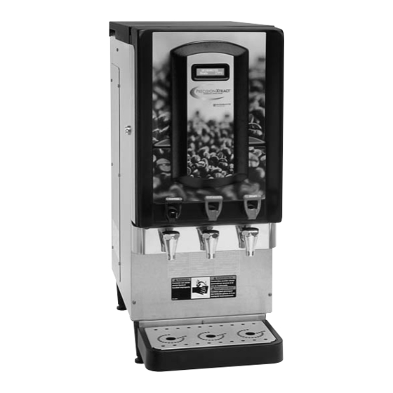
Introduction The Grindmaster-Cecilware Liquid Coffee Dispensers (LCD-2A) and the Liquid Coffee Chilled Dispenser (LCD-2R) deliver two types of coffee made from liquid concentrate plus hot water. • The dispenser can be set up for continuous draw (by the cup) for self-serve applications, or portion-control to fill carafes and decanters for wait staff. -
Page 3: User Replaceable Parts
User Replaceable Parts Page 3 Model LCD-2R and LCD-2A... -
Page 4: Warning Labels
Warning Labels The following warning labels were on your dispenser when it was shipped from the factory. They should remain on your dispenser in good, readable condition at all times. If one of your labels is missing or damaged, order a replace- ment label immediately. -
Page 5: Installation
Installation Water Inlet Connection: The National Sanitation Foundation requires the following for an NSF approved water hook-up: 1. A quick disconnect water connection or enough coiled tubing so that the machine can be moved for cleaning underneath. 2. An approved backflow prevention device, such as a double check valve to be installed between the machine and water supply. - Page 6 Installation (cont.) Electrical Hook-up: Ensure water connection is made to machine before proceeding and water source is turned ON. NOTE: Installation must be performed by a qualified electrician and must conform to all local and national codes. NOTE: Machine is factory configured for field wiring and power cord is not provided. If the machine is intended to configured to 120 volt operation, a conversion kit 63578 is available for the addition of a proper 120 volt power cord and a serial tag conversion procedure to match the serial tag to the 120 volt wattage of the heater.
-
Page 7: How To Dispense A Cup Of Coffee
Installation (cont.) 9. After the water tank has completed the fill cycle, the display located on the front door of the dispenser should indicate that the heating element has been activated. Allow 10-60 minutes for the water tank to reach operating temperature. -
Page 8: User Programming Instructions
User Programming Instructions refer to Figure C Setup Mode Open the door and insert Setup key into keyswitch above cooler compartment. Turn key ¼ turn clock- wise, the display on front of door will say ‘Setup Mode, Press Enter’. The two ‘Prime’ buttons and the Flush button now become the programming buttons: Prime 1 = UP, Prime 2 = DOWN, Flush = ENTER Press the Enter button (flush). -
Page 9: "Engineer" Program Settings
“Engineer” Program Settings TO BE PERFORMED BY A QUALIFIED SERVICE TECHNICIAN ONLY Engineer Mode To access engineer mode go into Setup mode, when the screen says ‘Setup Mode, Press Enter’ press the Hot Water tap – the display will now say ‘Engineer Mode, Press Enter’. The engineer has access to the following options: Max Temp [181F]: Sets the maximum temperature of the boiler. - Page 10 “Engineer” Program Settings TO BE PERFORMED BY A QUALIFIED SERVICE TECHNICIAN ONLY Engineer Mode (cont.) No prod, Stop Sel [Disabled]: No product, stop Selection. If enabled, when the coffee goes low during a dispense it will stop, giving a low measure. If disabled it will continue with the dispense even if the coffee goes low, then lock out once the dispense is finished.
- Page 11 “Engineer” Program Settings TO BE PERFORMED BY A QUALIFIED SERVICE TECHNICIAN ONLY Machine Fault Codes (cont.) 6: Water overheat The thermistor has detected the water is too hot. The boiler element contactor may have failed short circuit. The machine may be running high Wattage Power with a preheater. 7: Leak If the machine refills 15 times without a dispense the machine assumes a leak.
- Page 12 “Engineer” Program Settings TO BE PERFORMED BY A QUALIFIED SERVICE TECHNICIAN ONLY Programming Guide for Calibration of Mix Ratio (cont.) To check water flow rate and calibrate the actual mix ratio adjustment to match the programming mix ratio: IMPORTANT NOTE REGARDING PORTION OVERRIDE BUTTON: The default time setting for the override portion is 100 which equates to 10.0 seconds.
- Page 13 “Engineer” Program Settings TO BE PERFORMED BY A QUALIFIED SERVICE TECHNICIAN ONLY Programming Guide for Calibration of Mix Ratio (cont.) Worksheet Average water volume / Average concentrate volume = mix ratio Example: 600 ml water / 20 ml concentrate = 30:1 ratio Dispensed Water 1.
-
Page 14: Cleaning Instructions
Weekly Cleaning Instructions refer to Figure E NOTE: Some bag-in-box connectors require some disassembly for cleaning and sanitizing NOTE: Some bag-in-box connectors requires some extra steps for cleaning and sanitizing. 1. Remove fitting cap (a) from bag-in-box quick disconnect fitting if applicable. 2. - Page 15 Service and Cleaning Draining the Tank Always empty the tank before shipping. WARNING: Draining of tank should be performed by a qualified service technician. The tank contains 4 gallons (15.1 litre) of very hot water. May cause severe burns. 1. Prepare a minimum 5 gallon (17.5 litre) heat resistant container to drain the tank water into. 2.
-
Page 16: Troubleshooting Guide
Troubleshooting Guide A troubleshooting guide is provided to suggest probable causes and remedies for the most likely problem encountered. If the problem remains after exhausting the troubleshooting steps, contact Grindmaster- Cecilware Technical Service Department (800-695-4500, 8am-6pm, M-F). • Only qualified service personnel should perform inspection, testing, and repair of electrical equipment •... - Page 17 Troubleshooting Guide (cont.) WARNING: Risk of electrical shock. Disconnect power before removal of any machine access panels. Problem/Cause Remedy MACHINE DOES NOT POWER UP Machine is unplugged Ensure machine is plugged into power supply Power switch in OFF position Flip power switch to “ON” position (located at lower right corner of back of machine);...
- Page 18 Troubleshooting Guide (cont.) Problem/Cause Remedy LCD DISPLAY INDICATES “OVERFLOW” NOTE: Water must be drained from the tank below the float switch after the fault condition is diagnosed. Water level probe sensitivity is set too low Increase sensitivity of water fill circuit (see programming notes: Water Level Trip) Faulty or corroded level probe Remove level probe and grommet.
-
Page 19: Wiring Diagram
Wiring Diagram Page 19 Model LCD-2R and LCD-2A... -
Page 20: Grindmaster Corporation
Grindmaster® Coffee Grinders and Brewers • PrecisionBrew™ Brewing Systems • Espressimo® Espresso Machines Crathco® Hot Beverage Dispensers • Crathco® Cold and Frozen Beverage Dispensers • AMW Coffee and Tea Systems Tel (502) 425-4776 • Fax (502) 425-4664 • 1-800-695-4500 (USA & Canada only) P.O.
Need help?
Do you have a question about the LCD-2A and is the answer not in the manual?
Questions and answers