Table of Contents
Advertisement
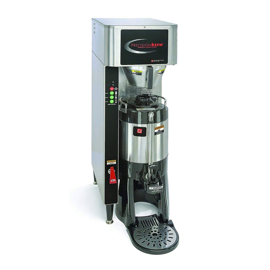
Shuttle
Brewer & Airpot/Shuttle
®
Operation and Instruction Manual
For Models PB-330, PB-430, PBVSA-330, PBVSA-430, PBIC-330, PBIC-430,
Table of Contents
Warning Labels . . . . . . . . . . . . . . . . . . . . . . . . . . 3
Installation and Start-up . . . . . . . . . . . . . . . . . . . 4
Operation . . . . . . . . . . . . . . . . . . . . . . . . . . . . . . 6
Adjustments . . . . . . . . . . . . . . . . . . . . . . . . . . . . 7
Programming . . . . . . . . . . . . . . . . . . . . . . . . . . . 9
Cleaning . . . . . . . . . . . . . . . . . . . . . . . . . . . . . . 13
. . . . . . . . . . . . . . . . . . . . . . . . . . . . . . 14
Precision Brew® Control Board . . . . . . . . . . . .15
Error Messages . . . . . . . . . . . . . . . . . . . . . 17
Filling Problems . . . . . . . . . . . . . . . . . . . . . 17
Heating Problems . . . . . . . . . . . . . . . . . . . . 19
Brewing Problems . . . . . . . . . . . . . . . . . . . . 21
Parts List . . . . . . . . . . . . . . . . . . . . . . . . . . . . . 24
Parts Photos . . . . . . . . . . . . . . . . . . . . . . . . . . . 25
VS-1.5(S) Cleaning and Sanitizing . . . . . . . . . .29
Wiring Diagrams . . . . . . . . . . . . . . . . . . . . . . . . 30
Prior authorization must be obtained from
Grindmaster Corporation for all warranty claims.
© Grindmaster Corporation, 2004
PRINTED IN U.S.A.
PB330E 230V, PB-430E 230V, PBVSA-330E 230V,
PBVSA-430E 230V, PBIC-330E 230V, PBIC-430E 230V
Models PB-330/PB-330E 230V
Grindmaster Corporation
4003 Collins Lane
Louisville, KY 40245 USA
(502) 425-4776
(800) 695-4500 (USA & Canada only)
(800) 568-5715 (Technical Service Only)
FAX (502) 425-4664
www.grindmaster.com
Brewers
®
Models PBIC-430/
PBIC-430E230V
Models PBVSA-430/
PBVSA-430E 230V
0607 Form # AM-344-04
Part # A090-840
Advertisement
Table of Contents

Related Manuals for Grindmaster AM-344-04


Summary of Contents for Grindmaster AM-344-04
-
Page 1: Table Of Contents
Wiring Diagrams ......30 Prior authorization must be obtained from Grindmaster Corporation for all warranty claims. © Grindmaster Corporation, 2004 PRINTED IN U.S.A. -
Page 3: Warning Labels
Warning Labels The following warning labels were on your dispenser when it was shipped from the factory. They should remain on your dispenser in good, readable condition at all times. If one of your labels is missing or damaged, order a replacement label immediately. Part # A546-445 Located on front splash panel and lid of machine. -
Page 4: Installation And Start-Up
Installation ELECTRIC SHOCK HAZARD! Installation of this appliance should be performed by qualified service personnel only. Improper installation could result in electrocution. Set-Up/Position 1) Remove the brewer from the packing material and attach its legs. 2) Position the brewer on a strong, stable table or counter. Check the level front to back and side to side. Adjust the legs to the correct level. - Page 5 Installation (cont.) Electric Hook-up The brewer is designed to operate at the specified voltage on the nameplate with a tolerance of ± 10% for voltage deviation. It is very important that the power line to the brewer be checked to make sure that the voltage is within 10% of the brewer’s rated voltage.
-
Page 6: Operation
Operation HOT LIQUID HAZARD! Water used for brewing coffee is very hot. Use caution when brewing, pouring, or transporting coffee. Accidental spills may result in severe burns. 1) Place an empty, warm Shuttle on the shelf, under the brew head. Turn on the warmer if available. 2) If the Shuttle is not warm, allow the warmer to heat the Shuttle. -
Page 7: Adjustments
Adjustments All adjustments to machine are accessible through the front display(s). Refer to specifics below and the Programming Routine section. All values are preset at the factory and may vary brewer to brewer. Temperature Adjustment Tank temperature can be adjusted from 170°F – 205°F (77°C – 96°C) through the front display. See Programming Routine section for procedure. - Page 8 Adjustments (cont.) Bypass “b-P” Brewer contains a bypass valve to control the amount of water to bypass coffee grounds and dilute the final brew. Bypass is available on Large and Medium brew cycles. Within the Programming Routine, the percent of the total brew volume to be bypassed can be set. Note: Adjusting bypass percent will not affect the finished brew volume.
-
Page 9: Programming
Programming (All values are preset at the factory and may vary brewer to brewer.) Settings Routine Large Programming For All Brewer Settings and Portion (refer to Table 1) 11. Press and hold both “up” and “down” arrows for 5 seconds. 12. - Page 10 Programming For All Brewer Settings and Large Portion (cont.) Table 1 1. PRESS-AND-HOLD UP & DOWN ARROWS FOR 5 SECONDS. 2. READY LIGHTS WILL FLASH. 3. PRESS BREW BUTTON FOR LARGE "L". 4. LARGE READY LIGHT FLASHES THROUGHOUT ROUTINE. 5. DISPLAY WILL READ AS FOLLOWS: TEMP SCALE TANK TEMP (170-205F) 4 minutes, 10 seconds shown...
- Page 11 Programming (cont.) Settings Routine Medium Programming For : Brew Time, Pulse Brewing & Bypass (refer to Table 2) 11. Press and hold both “up” and “down” arrows for 5 seconds. 12. All three brew lights will flash. 13. Press “Medium Brew” button. Only “Medium”...
- Page 12 Programming (cont.) Settings Routine Small Programming For : Brew Time & Pulse Brewing (refer to Table 3) 11. Press and hold both “up” and “down” arrows for 5 seconds. 12. All three “brew” lights will flash. 13. Press “Small Brew” button. Only “Small”...
-
Page 13: Cleaning
Cleaning Burn Hazard! Hot liquids and surfaces are present in this equipment. To avoid burns use caution when cleaning. Rinse hot parts with cold water before cleaning. Use gloves or a heavy cloth when removing hot parts from brewer. After Each Brew: 1) Dispose of grounds and rinse brew basket. -
Page 14: Service
Service The rest of this manual contains information to aid the service person who is working on this equipment. This page has information on performing diagnose problems which are divided into three basic systems: filling, heating, and brewing. Next is an call our Technical Service Department at 800-695-4500 (USA &... -
Page 15: Special Control Functions
Factory Specific Features The following sections describe features that are not intended to be used by the end user. These features, instead, are intended to help Grindmaster set up and test the machine. Factory/Field Test Menu This menu is intended to check product functionality both at the end of the factory line and in the field. The con- trol must be completely OFF (both sides) to enter field test. - Page 16 Factory/Field Test Menu (cont.) Step Function LED Test Firmware Version Date Code EEPROM Version Non Resetable Unit Counter Display Water Temperature Display Water Level 1 Display Water Level 2 Show Input Input Test Show Output Output Test Page 16 Operation All LEDs ON Display firmware version Not used...
-
Page 17: Troubleshooting
Troubleshooting The following pages are provided to help determine the cause of problems with operation of the brewers and to indicate the appropriate solution for the problems. For each problem, the possible causes should be checked in the order shown until the exact nature of the problem is determined. The following procedures must be performed by a qualified service technician. - Page 18 Troubleshooting (cont.) Problem Possible Causes Tank does not refill • No electrical power to equipment • No water supplied to equipment • No power to control board • No power to control board and transformer not powered. • No power to control board and transformer powered.
-
Page 19: Heating Problems
Troubleshooting (cont.) Problem Possible Causes Tank does not refill • Fill valve or control board is faulty Problem Possible Causes Tank does not heat • No electrical power to equipment • No power to control board Shuttle Brewers & Airpot/Shuttle Brewers Filling Problems Service Check •... - Page 20 Troubleshooting (cont.) Problem Possible Causes Tank does not heat • Low (long) electrode coated with lime or faulty. • Connection from control board to tank body faulty. • Connections from control board to heater relay faulty. • Line voltage connections to heater relay faulty.
-
Page 21: Brewing Problems
Troubleshooting (cont.) Problem Possible Causes Tank does not heat • Contactor faulty. • Heater faulty. • Control board is faulty. Problem Possible Causes Brew volume too • Portion selected on touchpad not correct. large or too small • Timer not set properly. Shuttle Brewers &... - Page 22 Troubleshooting (cont.) Problem Possible Causes Brew volume too • Sprayhead clogged. large or too small • Brew valves clogged with lime deposits. • Water supply pressure or flow rate not adequate. Brew volume • Water supply pressure fluctuates. erratic • Optional momentary Brew cycle will switch to indicate not start...
- Page 23 (Monday-Friday 8:00 am - 8:00 pm EST) or an authorized service center in your area. Please have the model and serial number ready so that accurate information can be given. Prior authorization must be obtained from Grindmaster Corporation’s Technical Services Department for all warranty claims.
-
Page 24: Parts List
Parts List for All Precision Brew Models Models PB-330, PB-430, PBVSA-330, PBVSA-430, PBIC-330, PBIC-430 ITEM DESCRIPTION Reference Front View Picture: Controller PB Single Relay, Heater 24vdc Valve, Inlet 24vac Terminal Block Spray Head Orifice Bypass Fitting Assy Water Inlet Switch Momentary ** PBIC only Reference Lower Warmer Picture: Faucet Hot Water Light Warmer... -
Page 25: Front View
Front View (refer to key on page 24) Lower Warmer (refer to key on page 24) (PB-430 pictured) Shuttle Brewers & Airpot/Shuttle Brewers Page 25... -
Page 26: Top View
Top View (refer to key on page 24) Tank Lid (refer to key on page 24) Page 26 Shuttle Brewers & Airpot/Shuttle Brewers... - Page 27 Shuttle Parts List for PB-330 and PB-430 only Upper Faucet (Part # A537-049) Shuttle Brewers & Airpot/Shuttle Brewers ITEM * S.S. Cover used until August 2001 A537-055 Handle A522132 Bonnet Nut A522120 Spring A537-047 Plastic Stem A522102 Silicone Seat Cup DESCRIPTION PART # Faucet Model ES...
- Page 28 Model VS-1.5 Vacuum Shuttle Parts List Page 28 Shuttle Brewers & Airpot/Shuttle Brewers...
-
Page 29: Cleaning And Sanitizing Instructions
These cleaning and sanitizing instructions are only a guideline to be used for the cleaning and sanitizing of the VS-1.5S and VS-S with VS-1.5. In-house cleaning and sanitizing methods may be more effective. Grindmaster assumes no responsibility for the food born illness and/or sickness caused by using improper sanitizing methods. - Page 30 Wiring Diagram - Precision Brew 430 Series Prior to May 2007 Models PB-430, PBVSA-430, and PBIC-430 Page 30 Shuttle Brewers & Airpot/Shuttle Brewers...
- Page 31 Wiring Diagram - Precision Brew 330 Series Prior to May 2007 Models PB-330, PBVSA-330, and PBIC-330 Shuttle Brewers & Airpot/Shuttle Brewers Page 31...
-
Page 32: Wiring Diagrams
Wiring Diagram Prior to May 2007 PB-430E 230V, PBVSA-430E230V, PBIC-430E 230V (Single or Three Phase Models) Page 32 Shuttle Brewers & Airpot/Shuttle Brewers... - Page 33 Wiring Diagram Prior to May 2007 PB-330E 230V, PBVSA-330E 230V, PBIC-330E 230V Brewers Shuttle Brewers & Airpot/Shuttle Brewers Page 33...
- Page 34 Wiring Diagram - Precision Brew 430 Series After May 2007 Models PB-430, PBVSA-430, and PBIC-430 Page 34 Shuttle Brewers & Airpot/Shuttle Brewers...
- Page 35 Wiring Diagram - Precision Brew 330 Series After May 2007 Models PB-330, PBVSA-330, and PBIC-330 Shuttle Brewers & Airpot/Shuttle Brewers Page 35...
- Page 36 Wiring Diagram After May 2007 PB-430E 230V, PBVSA-430E230V, PBIC-430E 230V (Single or Three Phase Models) Page 36 Shuttle Brewers & Airpot/Shuttle Brewers...
- Page 37 Wiring Diagram After May 2007 PB-330E 230V, PBVSA-330E 230V, PBIC-330E 230V Brewers Shuttle Brewers & Airpot/Shuttle Brewers Page 37...
- Page 38 Wiring Diagram - Heater Configuration (3 Heater) Page 38 Shuttle Brewers & Airpot/Shuttle Brewers...
- Page 39 Wiring Diagram - Heater Configuration (1 Heater) Shuttle Brewers & Airpot/Shuttle Brewers Page 39...
-
Page 40: Grindmaster Corporation
Grindmaster® Coffee Grinders and Brewers • PrecisionBrew™ Brewing Systems • Espressimo® Espresso Machines Crathco® Hot Beverage Dispensers • Crathco® Cold and Frozen Beverage Dispensers • AMW Coffee and Tea Systems Tel (502) 425-4776 • Fax (502) 425-4664 • 1-800-695-4500 (USA & Canada only) P.O.
Need help?
Do you have a question about the AM-344-04 and is the answer not in the manual?
Questions and answers