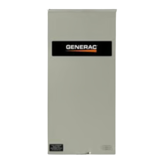
Advertisement
Quick Links
Neutral Terminal to Transfer Switch
Intended for Intended for All Transfer Switch
Models
DANGER
Automatic start-up. Disconnect utility power and render
unit inoperable before working on unit. Failure to do so
will result in death or serious injury.
WARNING
Consult Manual. Read and understand man-
ual completely before using product.Failure
to completely understand manual and prod-
uct could result in death or serious injury.
WARNING
Equipment damage. Only qualified service personnel
may install, operate, and maintain this equipment. Fail-
ure to follow proper installation requirements could result
in death, serious injury, and equipment or property
damage.
This instruction sheet brings Generac RX or RT series
transfer switches into compliance with NEC 2023. It pro-
vides instruction on how to add an additional neutral con-
trol wire between the switch and generator.
This additional neutral wire connects inside the switch at
the Neutral terminal. The additional wire connects to the
same connection point as the factory black and white wire
on the Neutral Terminal. Depending on transfer switch
model, the factory black and white wire coming from the
Neutral terminal comes from the Smart AC Module
(SACM) or Fused Control Module.
Follow all instructions in the Home Standby Installation
Manual to provide the connection point to the Home
Standby Generator.
Table -1. Components Included for Adding Neutral
Terminal
Part Number
Description
G026902
SCREW HHTT #8-32 X 1/4 CZ
G058353
LUG RNGTNG INS 22-18 X8
X.322
Neutral Terminal to Transfer Switch
INSTRUCTION SHEET
NOTE: For switches with a circuit breaker load center,
ring terminal and screw are not included. The neutral con-
nection will be connected to the load center neutral lug
bar.
Preparing for Installation
(D000191)
Automatic start-up. Disconnect utility power and render
unit inoperable before working on unit. Failure to do so
will result in death or serious injury.
(W000100)
NOTE: Neutral ring terminal is to be installed in tandem
with the normal installation of the transfer switch. Termi-
nate the white with blue stripe (00) neutral (18 AWG) wire
from Homestandby generator.
NOTE: Open and work with the specific transfer switch
model according to owner's manual.
(W000182)
Installing Generator Neutral Wire for
Transfer Switches without a Breaker
Load Center
Figure 1.
Qty.
1
1
DANGER
1. Disconnect utility, or turn service circuit breaker
OFF, to disconnect all power to transfer switch.
Figure 1. Automatic Transfer Switch (RXSW200A3
Shown as Example)
2. Verify back-up generation is de-activated.
(D000191)
014980
1
Advertisement

Summary of Contents for Generac Power Systems RXSW200A3
- Page 1 Terminal Part Number Description Qty. G026902 SCREW HHTT #8-32 X 1/4 CZ 014980 Figure 1. Automatic Transfer Switch (RXSW200A3 G058353 LUG RNGTNG INS 22-18 X8 X.322 Shown as Example) 2. Verify back-up generation is de-activated. Neutral Terminal to Transfer Switch...
- Page 2 Installing Generator Neutral Wire for Transfer Switches with a Breaker 014981 Load Center Figure 2. Remove Front Cover (RXSW200A3 Shown as Example) 1. Disconnect utility, or turn service circuit breaker OFF, to disconnect all power to transfer switch. 4. Locate the connection point on the neutral lug bar.
- Page 3 Figure 5. 014983 Figure 5. Neutral Lug Bar (RXG16EZA1W Shown as Example) 6. Assemble transfer switch panels. 7. Complete transfer switch installation according to the owner’s manual. 8. Test switch functions per the transfer switch own- er's manual. NOTE: Refer to the transfer switch’s owner’s manual for wiring and schematic diagrams.
- Page 4 Interconnect Diagram—Transfer Switch with Load Center INTERCONNECT DIAGRAM REVISION: “A” NSE W LOAD CNTR AIR COOLED GEN DATE: 03/09/23 DRAWING #: A0004115212 Neutral Terminal to Transfer Switch...
- Page 5 Interconnect Diagram—Non-Service Entrance Transfer Switch INTERCONNECT DIAGRAM REVISION: “C” NSE RTX AIR COOLED GEN DATE: 03/09/23 DRAWING #: A0004115210 Neutral Terminal to Transfer Switch...
- Page 6 SE RTX AIR COOLED GEN DATE: 03/09/23 DRAWING #: A0004115214 Part No. A0003330640 Rev. B 8/15/2023 Generac Power Systems, Inc. © 2023 Generac Power Systems, Inc. S45 W29290 Hwy. 59 All rights reserved Waukesha, WI 53189 Specifications are subject to change without notice.


Need help?
Do you have a question about the RXSW200A3 and is the answer not in the manual?
Questions and answers