Table of Contents
Advertisement
Available languages
Available languages
Owner's Manual
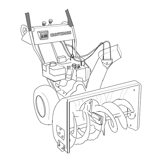
9 Horse Power
28" Two-Stage Wheel Drive
Snow Thrower
Model No.
247.888530
CAUTION: Before
using this product,
read this manual and
follow all safety rules
and operating
instructions.
Sears, Roebuck And Co., Hoffman Estates, IL 60179, U.S.A.
Visit our website: www.sears.com/craftsman
Printed in U.S.A.
•
Safety
•
Assembly
ES
•
Operation
•
Service
•
Maintenance
•
Español
770-10057D
(7/2000)
Advertisement
Table of Contents

Related Manuals for Craftsman 247.88853


Summary of Contents for Craftsman 247.88853
-
Page 1: Snow Thrower
247.888530 CAUTION: Before using this product, read this manual and follow all safety rules and operating instructions. Sears, Roebuck And Co., Hoffman Estates, IL 60179, U.S.A. Visit our website: www.sears.com/craftsman Printed in U.S.A. • Safety • Assembly • Operation •... -
Page 2: Table Of Contents
Sears will repair, free of charge, any defect in material and workmanship. If this Craftsman snow thrower is used for commercial or rental purposes, this warranty applies for only 30 days from the date of purchase. -
Page 3: Safe Operation Practices
SAFE OPERATION PRACTICES This symbol points out important safety instructions which, if not followed, could endanger the personal safety and/or property of yourself and others. Read and follow all instructions in this manual before attempting to operate your snow thrower. Failure to comply with these instructions may result in personal injury. -
Page 4: Maintenance And Storage
Use only attachments and accessories (such as wheel weights, counter weights, cabs, etc.) approved Following are representations of some of the safety labels on your Craftsman snowthrower. Please follow the instruction on these labels and maintain safety while using or servicing the equipment. -
Page 5: Hardware Pack
Lay the hardware pieces from the hardware pack on the figure here and you will have automatically sorted these according to the steps of the assembly procedure described later. (Only one unit of each hardware has been shown per group. The number in parenthesis indicates the total number of the hardware needed in that group.) Lock Washer... -
Page 6: Removing From Carton
Chute Chute Crank IMPORTANT: This unit is shipped with engine oil in the engine, but without gasoline. After assembly, see OPERATION section of this manual for fuel selection and fill-up. NOTE: To determine right and left hand sides of your snow thrower, stand behind the unit in the operating position. - Page 7 • Secure bottom hole in the handle to the snow thrower using 5/16 x .75" hex bolt and lock washer from the hardware pack (group A on page 5 ). Do not tighten at this time. See Figure 2. Lock Washer & Hex Bolt (1.75”) Right Handle...
- Page 8 • Insert hex bolt through the upper chute crank bracket, handle panel support, and upper left handle. Secure the bracket using cupped washer and hex nut. Make sure that the cupped side of the washer is set against the handle. Handle Panel Washer Support*...
- Page 9 • Tighten all loose hardware on the handle assembly in the following order — first the four hex bolts at the bottom of the handle, then the carriage bolts and lastly the hex bolts on the rear of the handle panel. Attaching Clutch Cables The clutch control cables are attached to the snow thrower.
- Page 10 • Place the cable barrel fitting into the hole in the trigger. You can find the triggers and associated hardware in group H of the hardware pack. See Figure 12. Trigger Assembly Inner Cable Cable Barrel Slot Fitting Figure 12 •...
-
Page 11: Final Adjustments
Final Adjustments Auger Control • To check the adjustment of the auger control, push forward the left hand clutch grip until the rubber bumper is compressed. There should be slack in the clutch cable. • Release the clutch grip. The cable should be straight. -
Page 12: Knowing Your Snow Thrower
Knowing Your Snow Thrower Read this owner’s manual and safety rules before operating your snow thrower. Compare WEAR YOUR SAFETY GLASSES illustration below with your snow thrower to familiarize yourself with the location of various controls and adjustments. Save this manual for future reference. The operation of any snow thrower can result in foreign objects being thrown into the eyes, which can result in severe eye damage. -
Page 13: Before Starting Engine
Operating Controls (See Figure 17.) Chute Crank The chute crank is located on the left hand side of the snow thrower. To change the direction in which snow is thrown, turn chute crank as follows: Turn clockwise to discharge to the left; Turn counterclockwise to discharge to the right. -
Page 14: To Start Engine
To avoid engine problems, the fuel system should be emptied before storage for 30 days or longer. Drain the gas tank, start the engine and let it run until the fuel lines and carburetor are empty. Use fresh fuel next sea- son. - Page 15 • Make sure that the auger drive and the traction drive levers are in the disengaged RELEASED position. • Move throttle control lever to FAST position. • Remove the keys from the plastic bag. Push key into the ignition slot. Make sure it snaps into place.
-
Page 16: Operating Tips
WARNING: To stop the auger, both levers must be released. To Throw Snow CAUTION: Check the area to be cleared for foreign objects. Remove, if any. • Start the engine following Starting instructions. • Rotate the discharge chute to the desired direction, away from bystanders and/or buildings. -
Page 17: General Recommendations
General Recommendations • Always observe safety rules when performing any maintenance. • The warranty on this snow thrower does not cover items that have been subjected to operator abuse or negligence. To receive full value from the warranty, operator must maintain the snow thrower as instructed in this manual. -
Page 18: Engine Maintenance
Lubrication For a view of the lubrication points on the snow thrower, see Figure 19. Sprocket Shaft • Lubricate the sprocket shaft with grease at least once a season or after every 25 hours of operation. IMPORTANT: Keep all grease and oil off of the friction wheel and the drive plate. -
Page 19: Spark Plug
colder 5W30 Viscosity Chart NOTE: Although multi-viscosity oils (5W30, 10W30 etc.) improve starting in cold weather, these multi- viscosity oils will result in increased oil consumption when used above 32 F. Check your snow thrower’s engine oil level more frequently to avoid possible engine damage from running low on oil. -
Page 20: Service And Ad Just Ments
SERVICE & ADJUSTMENTS WARNING: Always stop the engine, dis- connect spark plug wire and move it away from the spark plug before performing any adjustments or repairs. Never attempt to clean the chute or make any adjustments while the engine is running. Adjustments WARNING: Never attempt to clean chute or make any adjustments while engine is running. - Page 21 Carburetor WARNING: If any adjustments are made to the engine while the engine is running (e.g. carburetor), keep clear of all moving parts. Be careful of heated surfaces and mufflers. Minor carburetor adjustments may be required to compensate for differences in fuel temperature, altitude and load.
-
Page 22: Engine
• Remove the six hex nuts and lock washers which attach the auger housing assembly to the frame assembly. See Figure 26. WARNING: Do not attempt to change the auger belt without the help of an assistant. It is very important that one person, standing at the operating position, firmly hold the snow thrower housing to prevent it from tipping while the other person replaces the... - Page 23 • Reinstall the belt cover on front of the engine with the two self-tapping screws and flat washers. • Reattach the chute crank to the chute assembly with the hairpin clip and flat washer. NOTE: Make sure that the auger cable is routed in front of the belt.
- Page 24 Shift Arm Assembly Shift Arm Sprocket Assembly Friction Wheel Friction Wheel Figure 32 • Slide the hex shaft through the left side of the housing and through the friction wheel assembly. • Insert the hex shaft through the sprocket and the spacer.
-
Page 25: Preparing Engine/Snow Thrower
OFF-SEASON STORAGE If the snow thrower will not be used for 30 days or longer, or at the end of the snow season when the last possibility of snow is gone, the equipment needs to be stored properly. Follow storage instructions below to ensure top performance from the snow thrower for many more years. -
Page 26: Trouble-Shooting
TROUBLE-SHOOTING Trouble Possible Cause(s) Engine fails to start Fuel tank empty, or stale fuel. Blocked fuel line. Choke not in ON position Faulty spark plug. Key not in switch on engine. Spark plug wire disconnected. Primer button not depressed. Fuel shut-off valve closed (if so equipped). - Page 27 LABELS MAP...
-
Page 28: Repair Parts
SEARS CRAFTSMAN 9.0 H.P. SNOW THROWER MODEL 247.888530 NOTE: For painted parts, please refer to the list of color codes below. Please add the applicable color code, wherever needed, to the part number to order a replacement part. For instance, if a part, numbered 700-xxxx, is painted polo green, the part number to order would be 700-xxxx-0689. - Page 29 SEARS CRAFTSMAN 9.0 H.P. SNOW THROWER MODEL 247.888530 Key. No. Part No. 05931A Bearing Housing 684-0041C Auger Housing Assy. 28” 684-0065 Impeller Assy. 12” dia. 705-5226 Chute Reinforcement 710-0451 Carriage Bolt 5/16-18 x .75” Gr.2 710-0459A Hex Screw 3/8-24 x 1.5” Gr.5...
- Page 30 SEARS CRAFTSMAN 9.0 H.P. SNOW THROWER MODEL 247.888530 Drive Clutch Cable routed below axle and hooked here NOTE: For painted parts, please refer to the list of color codes below. Please add the applicable color code, wherever needed, to the part number to order a replacement part.
- Page 31 SEARS CRAFTSMAN 9.0 H.P. SNOW THROWER MODEL 247.888530 Key. No. Part No. 618-0043 Dogg Assembly: RH 618-0044 Dogg Assembly: LH 618-0303B Shift Assembly: Steerable Drive 656-0012A Friction Wheel Disc Assy. 684-0014B Shift Rod Assembly 684-0042CB Bearing 784-5731A Transmission Frame 684-0131A...
- Page 32 SEARS CRAFTSMAN 9.0 H.P. SNOW THROWER MODEL 247.888530 NOTE: For painted parts, please refer to the list of color codes below. Please add the applicable color code, wherever needed, to the part number to order a replacement part. For instance, if a part, numbered 700- xxxx, is painted polo green, the part number to order would be 700-xxxx-0689.
- Page 33 SEARS CRAFTSMAN 9.0 H.P. SNOW THROWER MODEL 247.888530 Part No. 629-0058 Harness for Headlight 684-0008A- Shift Arm Assembly 0637 684-0053A Lower Chute Crank Assembly 684-0066 Hardware Pack* 684-0102 Handle Panel Assembly w/ Tilt 684-0111A Handle Assembly Engagement (L.H.) 684-0112 Handle Assembly Engagement (R.H.)
- Page 34 SEARS CRAFTSMAN 9.0 H.P. SNOW THROWER MODEL 247.888530 Key. No. Part No. 712-0324 732-0705 — Key. No. Part No. 734-1709 738-0994 714-0143 Description Hex Lock Nut: 1/4-20 Cable Guide Craftsman Engine model 143.999005 Description Wheel Assembly: 16.5 x 4.8 Steerable Axle: 0.75”...
- Page 35 SEARS CRAFTSMAN 9.0 H.P. SNOW THROWER MODEL 247.888530 IMPORTANT: For a properly working machine, use Factory Approved Parts. V-Belts are specially designed to engage and disengage safely. A substitute (non-OEM) V-Belt can be dangerous by not disengaging completely. NOTE: For painted parts, please refer to the list of color codes below.
- Page 36 Craftsman Engine Model No. 143.999005 for Craftsman Snow Thrower Model 247.888530 18 35 83 81 82 139 186B 370C 370A 130B 264A 130A 149A 171 170 110A 370B 103 323 370C...
- Page 37 Craftsman Engine Model No. 143.999005 for Craftsman Snow Thrower Model 247.888530 Part Description 35385 Cylinder 27652 Dowel Pin 650820 Screw — Oil Drain Extension 30969 Extension Cap 30699C Governor Rod 30700 Governor Yoke 650494 Screw 33454 Governor Lever 29916 Governor Lever Clamp...
-
Page 38: Recoil Starter
Craftsman Engine Model No. 143.999005 for Craftsman Snow Thrower Model 247.888530 Table continued from previous page Part Description 35447A Blower Housing 650788 Screw 29747B Screw, Torx 264A 650802 Screw 33272B Cylinder Head Cover 35056 Muffler 31588 Locking Plate 651002 Screw... - Page 39 Craftsman Engine Model No. 143.999005 for Craftsman Snow Thrower Model 247.888530 CARBURETOR Part Description 640052 Carburetor (Incl. 184 of Engine Parts List) 631776A Throttle Shaft & Lever Ass’y. 1 631970 Throttle Return Spring 631778 Throttle Shutter 650506 Shutter Screw 632112 Choke Shaft &...
-
Page 40: Especificaciones Del Producto
GARANTIA DE INFORMACIÓN Por un año desde la fecha de compra cuando este expulsor de nieve Craftsman sea mantenido, lubricado y puesto a punto de acuerdo con las instrucciones de operación y mantenimiento en el manual del proprietario, Sears reparará libre de costo cualquier defecto de material o de mano de obra. - Page 41 PRACTICAS SEGURAS DE OPERACION Este simbolo senala instrucciones importantes de seguridad las cuales, si no se observan, podrian poner en peligro la seguridad personal y/o la propiedad suya y de otras personas. Lea y observe todas las instrucciones de este manual antes de intentar operar su expulsor de nieve motorizada. no cumplir con estas instrucciones puede resultar en lesiones personales, cuando vea este simbolo obedezca.
- Page 42 • Después de golpear un objeto, apague el motor, extraiga el cable de la bujía, e inspeccione completamente el expulsor de nieve por averías. Antes de volver a arrancar y operar el expulsor de nieve, repare las averías. • Si el expulsor de nieve comienza a vibrar anormalmente, apague el motor e inspeccione inmediatamente por la causa.
- Page 43 CONJUNTO DE FERRETERIA DE FERRETERIA Despliegue la ferretería de acuerdo con la ilustración para fines de identificación. Las piezas están ilustradas a la mitad de su tamaño aproximadamente. Los números de pieza se muestran entre paréntesis. (El conjunto de ferretería puede contener artículos adicionales que no se usan en su unidad.) Arandela de seguridad (4) Perno hexagonal (2)
-
Page 44: Herramientas Requeridas
Canaleta Manivela de la canaleta IMPORTANTE: Esta unidad ha sido despachada con aceite del motor pero sin gasolina en el motor. Después del ensamblado, vea la sección de OPERACION de este manual para selección y llenado de combustible. Nota: Para determinar los lados derecho e izquierdo de su expulsor de nieve, párese detrás de la unidad con el motor en la posición más alejada de usted. - Page 45 Mango Aleta del derecho mango Arandela de seguridad y perno hexagonal (5/8") Figura 2 • Coloque una de las dos aletas del mango, incluidas en el conjunto de ferretería (Grupo A en la página 6), sobre el orificio superior en el mango, de manera que el contorno de la aleta del mango coincida con el del mango.
- Page 46 hexagonal. Asegúrese que el lado acopado de la arandela está colocado contra el contorno de la manija. Arandela acopada y la tuerca hexagonal Soporte de la Manija* Soporte de la Manija de la Canaleta * Ya adjunto dentro de panel del mango Figura 5 •...
- Page 47 • Deslice los cables que se extienden desde el panel del mango a la canaleta dentro de la guía de cable ubicada al tope del motor. Vea la Figura 9 . Guía de Cable Figura 9 Fijacion De Los Cables Del Embrague Los cables de control del embrague están fijados a la limpiadora de nieve.
- Page 48 • Una vez que el casquillo se deslice dentro del orificio, gírelo en sentido contrario a las agujas del reloj una vuelta completa e inserte en el orificio en la palanca de cambios. Nota: Puede ser necesario mover la palanca de cambios fuera de la posición de sexta velocidad y moverla hacia la posición de quinta velocidad hasta que el casquillo se deslice dentro del orificio sin fuerza.
-
Page 49: Ajustes Finales
IMPORTANTE: Ensamble su expulsor de nieve, a continuación inspeccione los ajustes según las instrucciones y efectúe los ajustes finales necesarios antes de operar la unidad. El no seguir las instrucciones puede causar averías al expulsor de nieve. Ajustes Finales Ajuste del Control de la Hélice •... - Page 50 ANTES DE HACER FUNCIONAR SU EXPULSOR DE NIEVE LEA ESTE MANUAL DEL PROPIETARIO Compare las ilustraciones en este figura 17 con su expulsor de nieve para familiarizarse con la ubicación de varios controles y ajustes. Guarde este manual para referencia futura. La operación de un expulsor de nieve puede resultar en objetos despedidos contra los ojos, lo que puede resultar en lesiones graves de los ojos.
-
Page 51: Arranque Del Motor
Propulsor De Traccion/Seguro Del Embrague De La Espiral Sin Fin El embrague del propulsor de tracción está ubicado en el mango derecho. Accione el embrague del propulsor de tracción para enganchar la rueda motriz. Suelte para parar. Esta misma palanca también fija el embrague de la espiral sin fin de manera que se puede girar la manija de la canaleta sin interrumpir el proceso de limpieza de nieve. - Page 52 • Gire la perilla del regulador a la posición OFF. • Oprima el botón del cebador mientras cubre el orificio de ventilación. Saque el dedo del cebador entre cebados. No cebe para arrancar un motor caliente. Si la temperatura es mayor de 15 grados F cebe dos o tres veces y cuatro veces si es menor de 15 grados F.
- Page 53 Manejo De La Limpiadora De Nieve Las palancas de los gatillos están ubicadas en la parte inferior de los mangos y se usan para manejar su limpiadora de nieve. Nota: El embrague del propulsor debe estar enganchado al usar los gatillos para manejar la limpiadora de nieve. •...
-
Page 54: Mantenimiento
Recomendaciones Generales • Observe siempre las reglas de seguridad al efectuar el mantenimiento. • La garantía en este expulsor de nieve no cubre artículos que han estado sujetos a abuso o negligencia por el operador. El operador debe mantener el expulsor de nieve según las instrucciones de este manual, para recibir el valor completo de la garantía. -
Page 55: Mantenimiento Del Motor
Propulsor De Traccion/Control Del Propulsor De Traccion • Lubrique las levas en los extremos de las varas de control que bloquean entre sí los controles del propulsor de tracción y de la hélice una vez por temporada por lo menos o cada veinticinco horas de funcionamiento con grasa. - Page 56 ADVERTENCIA: Antes de efectuar cualquier ajuste o reparación, siempre apague el motor, desconecte el cable de la bujía y aléjelo de la bujía.Mientras el motor está funcionando, nunca trate de limpiar la canaleta ni efectuar ajustes. Ajustes Zapata Deslizante Puede ajustarse el espacio entre la plancha raspadora y el suelo.
- Page 57 Service Helices Las hélices están aseguradas al eje de la espiral mediante dos pernos de corte y contratuercas hexagonales. Si usted golpea un objeto extraño o se atasca con hielo, el expulsor de nieve está diseñado de manera que los pernos hexagonales se cortarán.
- Page 58 ADVERTENCIA: No intente cambiar la correa de la espiral sin fin sin la ayuda de un asistente. Es muy importante que una persona, parada en la posición operativa, sujete firmemente el bastidor de la limpiadora de nieve para evitar que vuelque mientras que la otra persona reemplaza la correa.
- Page 59 • Vuelva a fijar la manija de la canaleta al conjunto de la canaleta con el broche de cabello y la arandela plana. Nota: Asegúrese que el cable de la espiral sin fin esté encaminado al frente de la correa. Correa propulsora •...
- Page 60 • Sujetando el conjunto de la rueda de fricción, deslice el eje hexagonal fuera del lado izquierdo de la unidad. Caerá el separador del lado derecho del eje hexagonal y el piñon deberá colgar suelto en la cadena. • Levante el conjunto de la rueda de fricción entre el eje y los conjuntos del eje propulsor.
-
Page 61: Preparación Del Motor
ALMACENAMIENTO DE FUERA DE TEMPORADA Preparación del motor Si la unidad va a almacenarse por más de 30 días, prepare para almacenamiento como sigue: Es importante evitar que se formen depósitos de goma en las partes esenciales del sistema de combustible del motor tales como el carburador, filtro de combustible, manguera de combustible o tanque durante el almacenamiento. - Page 62 TABLA DE LOCALIZACION DE FALLAS Problema Causa(s) posible El motor fun- Unidad funcionando en CHOKE (REGU- ciona errático LADOR) Tuberia de gasolina bloqueada o combusti- ble rancio. Agua o suciedad en el sistema de combus- tible. Carburador mal ajustado. Pérdida de Cable de la bujía flojo.
- Page 63 Your Notes/Vuestro Apuntes...
- Page 64 In U.S.A. or Canada for in-home major brand repair service: Call 24 hours a day, 7 days a week 1-800-4-MY-HOME Para pedir servicio de reparación a domicillio — 1-800-676-5811 Au Canada pour tout le service ou les pièces — 1-800-469-4663 For the repair or replacement parts you need: Call 6 a.m.
Need help?
Do you have a question about the 247.88853 and is the answer not in the manual?
Questions and answers
Where to get parts for 20 year old craftsman 9hp 28” snowblower
You can find parts for the Craftsman 247.88853 9HP 28” snowblower in the parts list section of the owner's manual. The manual provides part numbers and descriptions for various components. Additionally, it suggests referring to color codes when ordering painted parts.
This answer is automatically generated