Table of Contents
Advertisement
Operator's Manual
2.5 HP (Max. Developed)
10" Inch Blade
5000 R.P.M.
BENCH TABLE SAW
Model: 137.232040
/
©
©
CAUTION:
Before using this Table Saw,
read this manual and follow
all its Safety Rules and
Operating
Instructions
•
Safety Instructions
•
Installation
•
Operation
•
Maintenance
•
Parts List
Customer
Help Line
1-800-843-1682
Sears, Roebuck and Co., Hoffman Estates, IL 60179 USA
Visit our Craftsman website: www.sears.com/craftsman
Part No. : 137232040001
Advertisement
Table of Contents

Related Manuals for COMPANION 137.232040


Summary of Contents for COMPANION 137.232040
- Page 1 Operator's Manual 2.5 HP (Max. Developed) 10" Inch Blade 5000 R.P.M. BENCH TABLE SAW Model: 137.232040 © © CAUTION: • Safety Instructions • Installation Before using this Table Saw, read this manual and follow • Operation all its Safety Rules and •...
-
Page 2: Full One Year Warranty
SECTION PAGE SECTION PAGE Know Your Table Saw ....... Warranty ........Product Specifications ....... Assembly and Adjustments ....Power Tool Safety ......Operation ........Maintenance ........Table Saw Safety ......Electrical Requirements and Safety ..Troubleshooting Guide ....... Accessories and Attachments ....Push Stick Pattern ...... - Page 3 Before using your table saw, it is critical that you read and understand these safety rules. Failure to follow these rules could result in serious injury or damage to the table saw. Good safety practices are a combination of common accessories.
- Page 4 PROVIDE ADEQUATE SUPPORT to the rear and ALWAYS USE SAW BLADE GUARD, splitter and anti-kickback pawls for every operation for which they the sides of the saw table for long or wide can be used, including through-sawing. Through- workpieces. sawing operations are those in which the blade cuts completely through the workpiece when ripping or AVOID KICKBACKS (work thrown back towards...
-
Page 5: Power Supply
POWER SUPPLY REQUIREMENTS GROUNDING INSTRUCTIONS IN THE EVENT OF A MALFUNCTION BREAKDOWN, grounding provides a path of least To avoid electrical hazards, fire hazards or damage to resistance for electric current and reduces the risk of the table saw, use proper circuit protection. Always electric shock. -
Page 6: Recommended Accessories
RECOMMENDED ACCESSORIES UNPACKING CHECKING CONTENTS • For missing or damaged parts on initial purchase, call 800-843-1682 • To order parts, call 800-366-7278 Visit your Sears Hardware Department or see the Craftsman Power and Hand Tools Catalog to purchase Separate all parts from packing materials. Check each recommended accessories for this power tool. - Page 7 UNPACKING YOUR TABLE t_. J ..
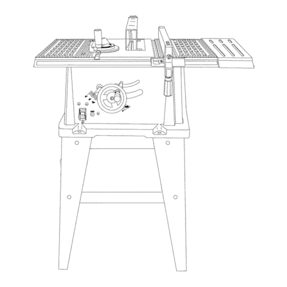
- Page 8 Blade Guard Table insert Miter gauge Side table _ip fence extension Bevel angle Pointer & scale Overload reset switch Blade bevel lock knob Blade elevation & tilting handwheel ON/OFF switch with safety Front stand mounting holes Stand ..j Splitter Blade Anti-Kickback Pawls...
- Page 9 ASSEMBLE STAND (Fig.A) Assemble table saw to stand (Fig. A-l) 1. Unpack allparts andgroup by typeandsize(seeFig.1). Place protective cardboard or old blanket on floor to Refertothepartslistforcorrect q uantities. protect the saw table surface. 2. Attachonelonguppersupport ( 4)to topof leg (1) using Place the saw up side down on the protective material (see Fig.
-
Page 10: Keeping The Area Clean
ASSEMBLE BLADE RAISING & TILTING WHEEL SAW MOUNTED TO WORK SURFACE (FIG.B) 1. If the leg set will not be used, the saw must be (FIG. C) 1. Attach blade raising & tilting hand wheel (1) to properly secured to a sturdy workbench using the the height regulating bolt (2). - Page 11 1. Liftupward onripfencehandle (2)sotherear Fig. F holding clamp isfullyextended.. 2. Place theripfenceonthesawtable, e ngaging therearfenceclamp firstthenlowering t hefront endontothetable. 3. Pushdownonthefencehandle to lock. Fig. E INSTALLING AND CHANGING THE BLADE --" (FIG. H, I, J) • To avoid injury from an accidental start, make sure the switch is in the OFF position and the plug is not connected to the power source outlet.
-
Page 12: Blade Guard Assembly
4. Remove thearbornut(5)andouterflange (6). external toothlockwasher ( 4)ontotheblade 5.Install t hesawbladeontothearborwiththeblade guard mounting bolt(1).(Fig.K) teethpointing toward thefrontofthesaw. 6. Install t heflange(6)against t hebladeandthread Fig. K thearbornut(5)asfaraspossible byhand. Ensure thatthebladeisflushagainst t heinner sideoftheblade flange. Blade Guard Splitter To avoid possible injury and damage to the workpiece be sure to install the blade with the teeth pointing toward the front of table in the direction of the rotation arrow on the blade guard. -
Page 13: Miter Gauge Adjustment
Fig. M • Loosen the two screws (3) and lift up on the Kickback pawl handle (2). • Hold the fence bracket (4) firmly against the front of the saw table. Move the far end of the fence until it is parallel with the miter gauge groove. - Page 14 BLADETILTING MECHANISM BLADE PARALLEL TO THE MITER GAUGE Thesawbladecanbetiltedtwodifferent w ays. GROOVE (FIG. Q, R) This adjustment was made at the factory, but it RAPID BLADETILTING (FIG.P) should be rechecked and adjusted if necessary. 1. Loosen bladebevel l ockknob(2). 2. Slide the entire handwheel assembly (1) to To prevent personal injury: desired location.
-
Page 15: Tools Required
Additional blade adjustments (Fig. R) While standing at the front of the saw, use a medium size flat blade screw driver and gently TOOLS REQUIRED pry the front of the blade alignment rod to the RIGHT or LEFT. Simultaneously measure the •... -
Page 16: Bevel Pointer Adjustment
0° BEVEL STOP (FIG. S ) 45 ° BEVEL STOP (FIG. U) 1. Raise thebladetomaximum height b yrotating Raise the blade to maximum height by rotating thehandwheel counter c lockwise. the handwheel counter clockwise. 2. Loosen bevel a nglelockknob. Loosen bevel angle lock knob. 3. -
Page 17: Basic Saw Operations
CUTTING OPERATIONS BASIC SAW OPERATIONS There are two basic types of cuts: ripping and crosscutting. Ripping is cutting along the length and ON/OFF SWITCH (FIG. V) with the grain of the workpiece. Crosscutting is cutting The switch (2) is located on the front panel of the saw either across the width or across the grain of the base. -
Page 18: Ripping Small Pieces
AVOIDKICKBACK bypushing forward thatsection of Never attempt to pull the workpiece backwards during theworkpiece t hatwillpassbetween thebladeandthe a cutting operation. This will cause kickback and fence.Usea pushstickat alltimes. serious injury to the user can occur. RIPPING SMALL PIECES Fig. W Avoid injury from the blade contact. - Page 19 Fig. Y Fig. BB MITERING (FIG. CC) 00-45 ° MITER ANGLE This sawing operation is the same as crosscutting except the miter gauge is locked at an angle other than 90 °. BEVEL CROSSCUTTING (FIG. AA) 0°-45 ° BLADE BEVEL & 90 ° MITER ANGLE WARNING - Always work to the left side of the blade This cutting operation is the same as crosscutting except during this type of cut.
- Page 20 Fig. DD USING WOOD FACING ON THE RIP FENCE (FIG. When performing some special cutting operations, add a wood facing (1) to either side of the rip fence (2). Use a smooth 3/4"thick board (1) that is as long as the rip fence.
-
Page 21: Maintenance
MAINTAINING YOUR TABLE SAW Fig. FF GENERAL MAINTENANCE For your own safety, turn the switch OFF and remove the switch key. Remove the plug from the power source outlet before maintaining or lubricating your saw. 1. Clean out all sawdust that has accumulated inside the saw cabinet and the motor. - Page 22 To avoid injury from an accidental start, turn the switch OFF and always remove the plug from the power source before making any adjustments. • Consult your local Sears Service Center if for any reason the motor will not run. SYMPTOM POSSIBLE CAUSES CORRECTIVE ACTION...
-
Page 23: Push Stick Construction
PUSH STICK CONSTRUCTION • This is a full-size drawing (actual size) • Use good quality plywood or solid wood • Use ½" or ¾" material • Push stick MUST be thinner than the width of material being cut Cut Here To Push ½"... - Page 24 WARNING I When servicing use only COMPANION replacement parts. Use of any other parts many create a HAZARD or cause product damage. Any attempt to repair or replace electrical parts on this Table Saw may create a HAZARD unless repair is done by a qualified service technician.
-
Page 25: Saw Parts List
10" TABLE SAW PARTS LIST MODEL: 137.232040 O, {_1' ()KqJ ):> O},,IS 7,I'_... - Page 26 10" TABLE SAW PARTS LIST MODEL: 137.232040 Size I.D. Description I.D. Description Size 0HV5 BALL BEARING 6204LLU 0QED SUPPORT PLATE 0JAL EXT.TOOTH LOCKWASHER 0QEH --IELD ASS'Y OJEE C-RING A-17 0QEJ %RMATURE ASS'Y OJFY PARALLEL 4x4-!2 0QEK VIOTOR NAMEPLATE 0JX3 HEX. SOC. SET SCREW M5"0.8-8 OQM2 3RUSH HOLDER ASS'Y...
- Page 27 10" TABLE SAW PARTS LIST MODEL: 137.232040 STAND I.D. No. Size Description 2003 LONG BOTTOM SUPPORT BRACKET L=616mm 2004 SHORT BOTTOM SUPPORT BRACKET L=528.4mm 2005 LONG UPPER SUPPORT L=462mm 2006 SHORT UPPER SUPPORT L=428mm, 2007 BRACKET L=595.6mm 093B FOOT PAD OJ4F FLAT WASHER €8X16-2.5...
Need help?
Do you have a question about the 137.232040 and is the answer not in the manual?
Questions and answers