Table of Contents
Advertisement
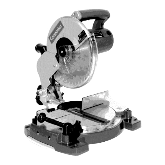
Operator's Manual
lO-in. Compound
Miter
Double Insulated
Model No.
172.21199
Save this manual for future reference.
CAUTION:
Read, understand and follow
all Safety Rules and Operating Instructions
in this manual before using this product.
Sears, Roebuck and Co., Hoffman Estates, IL 60179 U.S.A.
• SAFETY
• FEATURES
• ADJUSTMENT
• OPERATION
• MAINTENANCE
Advertisement
Table of Contents

Related Manuals for COMPANION 172.21199


Summary of Contents for COMPANION 172.21199
- Page 1 Operator's Manual lO-in. Compound Miter Double Insulated Model No. 172.21199 • SAFETY • FEATURES Save this manual for future reference. • ADJUSTMENT • OPERATION CAUTION: Read, understand and follow • MAINTENANCE all Safety Rules and Operating Instructions in this manual before using this product. Sears, Roebuck and Co., Hoffman Estates, IL 60179 U.S.A.
- Page 2 Warranty................... Page Safety Instructions ................. Pages 3-11 Safety Symbols ................Page Glossary of Terms ..............Pages 12-13 Unpacking ..................Page Loose Parts ..................Page Tools Needed ................... Page Description ..................Pages 16-21 Assembly..................Pages 22-23 Adjustments ..................Pages 24-30 Operation ..................
-
Page 3: Safety Symbols
iKWARNING: BE SURE to read and understand all safety instructionsin this manual, includingall safety alert symbols such as DANGER, WARNING and CAUTION, BEFORE using this saw. Failure to follow all instructions listed below may result in electric shock, fire and/or serious personal injury. - Page 4 ELECTRICAL SAFETY GENERAL ELECTRICAL CONNECTIONS DANGER: To reduce the risk of electrocution: 1. Use only identical replacement parts when servicing. Servicing should be performed by a qualified service technician. 2. Do not use in rain or where floor is wet. This tool is intended for indoor use only. 110-120-Volt, 60 Hz.
- Page 5 GENERAL ELECTRICAL CONNECTIONS cont. Fig. A 3-Prong Plug Properly Grounded NOTE: The adapter illustrated is for use 3-Prong only if you already have a properly Outlet grounded 2-prong outlet. Prong NOTE: In Canada, the use of a temporary adapter is not permitted by the Canadian Electrical Code Make sure GroundingLug...
- Page 6 Some of the following symbols may be used on this tool. Please study them and learn their meaning. Proper interpretation of these symbols will allow you to operate the tool better and safer. SYMBOL NAME DESIGNATION / EXPLANATION Wet Conditions Alert Do not expose to rain or use in wet conditions.
-
Page 7: Work Area Safety
WORK AREA SAFETY 1. ALWAYS keep your work area clean and well lit. DO NOT leave tools or pieces of wood on the saw while it is in operation. Cluttered benches and dark areas invite accidents. 2. DO NOT operate power tools in explosive atmospheres, such as in the presence of flammable liquids, gases, or dust. - Page 8 TOOL USE AND CARE SAFETY 1. NEVER leave the tool running unattended. ALWAYS turn it off. DO NOT leave the tool until it comes to a complete stop. 2. DO NOT use the tool if the switch does not turn it "On" or "Off", Any tool that cannot be controlled with the switch is dangerous.
- Page 9 ADDITIONAL SPECIFIC SAFETY RULES FOR MITER SAWS cont. 5. ALWAYS use a clamp to secure the workpiece, when possible. 6. ALWAYS be sure the blade path is free of nails. ALWAYS carefully inspect lumber and remove all nails BEFORE cutting. 7.
- Page 10 ADDITIONAL SPECIFIC SAFETY RULES FOR MITER SAWS cont. /% WARNING: Blade continues to turn after power to saw cuts off.To avoid possible serious injury, after releasing trigger switch to cut power, allow the saw blade to stop rotating BEFORE raising the blade out of the workpiece 20.
-
Page 11: Service Safety
ADDITIONAL SPECIFIC SAFETY RULES FOR MITER SAWS cont. WEAR YOUR ,AkWARNING: The operationof any saw can result in foreign objects being thrown intoyour eyes, whichcan result in severe eye damage. Before beginningpower tooloperation,ALWAYS wear safety goggles or safety glasses with side shieldsand a full face shield when needed.We recommenda Wide Vision Safety Mask for use over eyeglasses or standardsafety glasses with side shield, both availableat Sears Retail Stores. - Page 12 Arbor The shaft on which a blade or cutting tool is mounted. Revolutions Per Minute (RPM) The number of turns completed by a spinning object in one minute. FPM or SPM Feet per minute (or strokes per minute), used in reference to blade movement. No Hands Zone The area between the marked lines on the left and right side of the miter table base, This zone is identified by no hands zone labels placed inside the marked lines on the...
- Page 13 Non-Through Cuts Any cutting operation where the blade does not extend completely through the thickness of the workpiece. Resaw A cutting operation to reduce the thickness of the workpiece to make thinner pieces. Heel Alignment of blade to fence. Leading End The end of the workpiece pushed intotool first.
- Page 14 1. Remove all packing materials from around your saw. 2. Carefully lift the saw from carton and place it on a level work surface. The saw is heavy, so get help, if you need it, to help avoid injuring your back. 3.
- Page 15 Fig.1 The following items are included with your compound miter saw. • Work Clamp • Blade Wrench • Owner's Manual Work Clamp Blade Wrench A_ WARNING: The use of attachments or accessories that are not recommended might be dangerous and could cause serious personal injury. Fig.2 ..
- Page 16 KNOWYOUR SAW (see fig. 6) Before attempting to use your saw, familiarize yourself with all of the operating features and safety requirements. i WARNING: DO NOT allow familiarity with your saw to make you careless. Remember that a careless fraction of a second is sufficient to inflict serious injury. 12-Amp Motor Your saw has a powerful 12-amp motor that provides the power for a variety of cutting applications.
- Page 17 Fig. 3 Phillips Screw (A) Phillips Screw (B) Lower Blade Spindle Guard Lock Pin Notch Fig. 4 Lower Blade Guard Blade Flats on Spindle Blade Outer Blade with Flats Blade To Loosen...
- Page 18 TO REPLACE BLADE (See Figs. 3 - 5) cont. 7. Use the blade wrench (included) to loosen and remove the blade bolt. Turn the blade bolt CLOCKWISE to loosen and remove. 8. Remove the outer blade washer behind the blade bolt.Then carefully remove the black Double "O" flat outer blade washer.
- Page 19 KNOW YOUR SAW cont. Miter Lock Levers (See Fig. 7) The miter lock levers securely lock the saw table at the desired miter angles. Spindle Lock Button (see Fig. 8) The spindle lock button on your saw allows you to lock the spindle that keeps the blade in your saw from rotating.
- Page 20 Fig. 6 Saw Arm KNOW YOUR SAW cont. Bevel Scale Upper Blade Guard Bevel Lock Knob Lower Bevel Blade Guard Fence Lock Knob_ Miter "No Hands" Lock Label Lever Base Miter Scale Hold-Down \ Miter Table Work Clamp Fig. 8 Trigger Spindle Levers...
- Page 21 KNOW YOUR SAW cont. Fig. 9 Trigger Switch Blade Diameter 10 in. Blade Arbor 518 in. 4500 RPM No-Load Speed Rating 12 Amperes Input 120 Volts, 60 Hz AC Only Cutting Capacities When the miter angle (miter table) is set at 0° and the bevel angle is set at 0°: Your saw will cut materials up to a maximum of 5 1/2 in.
- Page 22 /_ WARNING: attempt DO NOT t o modify this tool or create accessories not recommended for this tool. Any such alteration or modification is misuse and could result in a hazardous condition leading to possible serious personal injury. / WARNING: DO NOT connect to power supply until assembly is complete.
- Page 23 Work Clamp (See Fig. 11) The work clamp provides greater control by clamping the workpiece to the fence or the saw table. It also prevents the workpiece from creeping towards the saw blade. This is very helpful when cutting compound miters. Depending on the cutting operation and the size of the workpiece, it may be necessary to use a C-clamp (not included) instead of the work clamp to secure the workpiece prior to making the cut.
- Page 24 Your compound miter saw has been adjusted at the factory for making very accurate cuts. However, some of the components may have been jarred out of alignment during shipping. Also over a period of time, some readjustment will probably become necessary due to wear. After unpacking your saw, check the following adjustments BEFORE using your saw.
- Page 25 SQUARING THE MITER TABLE TO THE FENCE (See Figs. 12 - 15) cont. Miter ,Fence Fence Square, Table Plate Fig. 14 Fig, 15 Framing Square Socket Head Screws Throat BACK VIEW VIEW OF MITERTABLE NOT SQUARED Fonco Plate OF SAW TOTHE FENCE, ADJUSTMENTS ARE NEEDED...
- Page 26 SQUARING THE SAW BLADE TO THE FENCE (See Figs. 16-19) 1, Unplug the saw. / WARNING: Failure to unplug your saw could result in accidental starting causing possible serious personal injury! 2. Pull the saw arm all the way down and engage the lock pin to hold the saw arm in the transport position.
- Page 27 SQUARING THE SAW BLADE TO THE FENCE (See Figs. 16-19) cont. Fig. 18 Fig. 19 He]( Head Fence Screws Mounting Bracket Base Miter Table Blade SQUARING THE SAW BLADE TO THE MITER TABLE (See Figs. 20-23) 1. Unplug the saw. I i_WARNING: Iseriouspersonal injury, Failure t°...
- Page 28 SQUARING THE SAW BLADE TO THE MITER TABLE (See Figs. 20-23) cont. Fence Table Table Blade Blade Fig. 22 Positive Fence\ Miter Table Blade VIEW OF BLADENOTSQUARED WITH MITER TABLE, ADJUSTMENTS ARE NEEDED Your saw has two scale indicators, one on the bevel scale and one on the miter scale. After squaring adjustments have been made, it may be necessary to loosen the indicator screws and reset them to zero.
-
Page 29: Pivot Adjustments
PIVOT ADJUSTMENTS NOTE: These adjustments were made at the factory and under normal circumstances do not require readjustment. Travel Pivot Adjustment Your saw arm should rise completely to the up position by itself. To avoid risk of personal injury, if your saw arm does not rise by itself or if there is play in the pivot joints, have your saw serviced at a Sears Service Center before using. - Page 30 Depth Stop Adjustments (See Figure 25) 1. Unplug the saw. I /_ WARNING: To prevent personal injury, ALWAYS disconnect the plug from power source BEFORE assembling parts, making adjustments or changing blades. 2. To adjust the depth stop use a 10mm wrench or adjustable wrench to loosen the hex nut at the rear of the miter saw arm.
-
Page 31: Miter Saw
Depth Stop Adjustments (See Figure 25) cont. i WARNING: DO NOT allow familiarity with your tool make you careless, remember, that a careless fraction of a second is sufficient to inflict severe injury. / WARNING: ALWAYS wear safety goggles or safety glasses with side shields when operating tools. - Page 32 CROSSCU'I'FING (See Figure 26) cont. Fig. 26 Clamp To Miter Cut 1. Unplug the saw. / WARNING: To prevent personal injury, ALWAYS disconnect the plug from power source BEFORE assembling parts, making adjustments or changing blades. 2. Pull out the lock pin and lift the saw arm to its full height. 3.
-
Page 33: Bevel Cutting
To Miter Cut cont. 10. BEFORE turning on the saw, perform a dry run of the cutting operation just to make sure that no problems will occur when the cut is made. 11. Hold the saw handle firmly when squeezing the trigger switch. Allow several seconds for the blade to reach maximum speed. -
Page 34: Compound Miter Cutting
To Bevel Cut cont. 6. Loosen the bevel lock knob and move the saw arm to the left to the desired bevel angle. 7. Bevel angles can be set from 0° to 45 °. 8. Align the indicator point with the desired angle. g. - Page 35 COMPOUND MITER CU'i-rlNG cont. To Make a Compound Miter Cut With Your Miter Saw (see Figures 29 and 30) 1. Unplug the saw. WARNING: To prevent personal injury,ALWAYS disconnect the plug from power source BEFORE assembling parts, making adjustments or changing blades. 2.
-
Page 36: Support Long Workpieces
COMPOUND MITER CUTTING cont. Fig. 30 SUPPORT LONG WORKPIECES Long workpieces require extra supports. The supports should be placed along the workpiece so it does not sag. The support should allow the workpiece to lay flat on the base of the saw and work table during the cutting operation. - Page 37 CUTTING COMPOUND MITERS To help you to make the correct settings, use the compound angle setting chart below. Since compound cuts are the most difficult to accurately obtain, plan carefully and make trial cuts in scrap material prior to making your required cut. _=i r I l _=#11 MUI_IDCM...
-
Page 38: Cutting Crown Molding
CUTTING CROWN MOLDING Your compound miter saw is excellent for cutting crown molding. In order for it to fit properly, crown molding must be compound mitered with extreme accuracy. To fit flat against the ceiling and wall, the sum of the angles of the crown molding's two connecting surfaces must equal 90°. - Page 39 CUTTING CROWN MOLDING cont. Bevel Type of Cut Angle Setting Left side, inside 90° corner 1. Top edge of moldingagainst fence 33.85 ° 2. Miter table set right 31.62 ° 3. Save left end of cut Right side, inside 90 ° corner 1.
-
Page 40: Clamping Wide Workpieces
CLAMPING WIDE WORKPIECES When cutting wide workpieces (such as 2-in x 6-in. boards), the boards should ALWAYS be clamped with a hold-down clamp or a C-clamp. /_WARNING: When servicing, use only identical replacement parts. Use of any other part may create a hazard or cause product damage. Z_WARNING: ALWAYS wear safety goggles or safety glasses with side shields during power tool operation, or when blowing dust. -
Page 41: Brush Replacement
BRUSH REPLACEMENT (See Figure 34-35) Your saw has externally accessible brushes that should be periodically checked for wear. When replacement is necessary, follow these steps: 1. Unplug the saw. / WARNING: To prevent personal injury, ALWAYS disconnect the plug from power source BEFORE assembling parts, making adjustments or changing blades. - Page 42 Sears offers a large selection of blades, table extensions, roller tables, extension cords and more that are ideal for use with your 10-inch compound miter saw for a variety of cutting needs. / .kWARNING: The use of attachments or accessories not sold by Sears may result in serious personal injury.
- Page 43 NOTES...
- Page 44 Your Home For repair-in your home-of all major brand appliances, lawn and garden equipment, or heating and cooling systems, no matter who made it, no ma_er who sold it! For the replacement parts, accessories owner's manuals that you need to do-it-yourself. For Sears professional installation of home appliances...
Need help?
Do you have a question about the 172.21199 and is the answer not in the manual?
Questions and answers