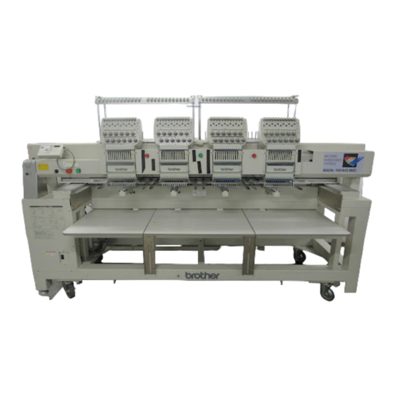
Brother BES-1240BC Instruction Manual
Nine needle four head electronic embroidery machine; twelve needle four head electronic embroidery machine
Hide thumbs
Also See for BES-1240BC:
- Parts manual (143 pages) ,
- Maintenance manual (14 pages) ,
- Referencia de máquina (14 pages)
Table of Contents
Advertisement
Advertisement
Table of Contents

Related Manuals for Brother BES-1240BC


Summary of Contents for Brother BES-1240BC
- Page 1 BES-940 INSTRUCTION MANUAL BES-1240 Please read this manual before using the machine. Please keep this manual within easy reach for quick reference. NINE NEEDLE FOUR HEAD ELECTRONIC EMBROIDERY MACHINE TWELVE NEEDLE FOUR HEAD ELECTRONIC EMBROIDERY MACHINE...
- Page 2 Precautions • Unauthorized commercial or industrial use of trademarks or copyrighted materials (such as paintings, drawings, photos, logos, etc.) owned by other companies or persons is illegal. The use of such materials without the permission of their owners may result in criminal or civil liability. •...
-
Page 3: Safty Instructions
....This symbol ( ) indicates something that you must do. The picture inside the circle indicates the nature of the thing that must be done. (For example, the symbol at left means "you must make the ground connection".) BES-940BC • BES-1240BC... -
Page 4: Notes On Safety
When securing the cords, do not bend the cords excessively or fasten them too hard with staples, otherwise there is the danger that fire or electric shocks could occur. BES-940BC • BES-1240BC... -
Page 5: Maintenance And Inspection
Any problems in machine operation which re- • When carrying out inspection, adjustment sult from unauthorized modifications to the ma- and maintenance chine will not be covered by the warranty. • When replacing consumable parts such as the rotary hook and knife. BES-940BC • BES-1240BC... -
Page 6: Warning Labels
Direction of operation CAUTION Do not touch this part during activitation or for 30 minutes after shut-off. Otherwise burns may result. BES-940BC • BES-1240BC... - Page 7 Finger guard Belt cover BES-940BC BES-940BC • BES-1240BC...
-
Page 8: Procedure Of Reading This Manual
- BES-940BC (9 needles) - BES-1240BC (12 needles) Explanation for individual model is provided by identifying the model name. Check the model before using the machine. The software display is BES-1240BC. Configuration of this manual This manual consists of the following chapters:... - Page 9 List of Error Codes Provides information on error codes and action to be taken. Chapter 12 Troubleshooting Provides troubleshooting for the machine. Connection and Installation of Optional Equipment Describes connections between the machine/computer and optional equipment available. BES-940BC • BES-1240BC...
-
Page 10: Table Of Contents
Functions of Operation Panel ..............60 Operation Panel ....................60 Switches at Machine Heads ................62 Switches on Tension Plate ................62 Flowchart of Preparation for Embroidering ..........64 Run the Software ....................65 Turn on the Machine Power ................65 BES-940BC • BES-1240BC... - Page 11 Opening Embroidery Data ................ 99 Setting Display ..................100 Centering ......................100 Zoom ....................... 100 Needle Penetration ..................102 Embroidering Start/End ................... 102 Trim and pause ....................102 Microstitch ....................... 103 Needle Bar and Speed Range ................ 103 BES-940BC • BES-1240BC...
- Page 12 Settings before Turning On the Machine ..........132 Displaying the Tool Bar ................... 132 Displaying the Status Bar ................133 Upgrading the Version of Interface Board ............133 Reset Interface Board ..................133 Communication Port ..................133 Language ......................134 BES-940BC • BES-1240BC...
- Page 13 Boring ......................159 Thread Breakage Sensor ................160 Automatic Step Back ..................161 Automatic Hoop Feed ..................162 End of embroidery ................... 162 Mending ......................163 Adjust ......................164 Activating speed up of driving shaft ..............165 BES-940BC • BES-1240BC...
- Page 14 Resetting Emergency Stop ..............193 3. Permission for Hoop Movement ............194 4. Measures against Thread Breakage ..........195 4-1. Remedies ..................... 195 4-2. Mending ....................196 5. Jog Embroidering ................198 6. Hoop Feed Position ................198 BES-940BC • BES-1240BC...
- Page 15 Chapter 9 Maintenance 1. Cleaning Rotary Hook ..............224 2. Oiling ....................225 2-1. Head ....................225 3. Greasing .................... 227 3-1. Head ....................227 3-2. Feed Guide Section ................231 3-3. Lower shaft module ................232 BES-940BC • BES-1240BC...
- Page 16 Chapter 11 List of Error Codes Chapter 12 Troubleshooting Mechanical Section ................. 256 Electrical Section ..................258 Personal Computer Section ..............268 Connection and Installation of Optional Equipment 1. Attaching Bobbin Winder ..............270 2. Tape Reader ..................272 BES-940BC • BES-1240BC...
-
Page 17: Chapter 1 An Introduction Of Embroidery Machine
Chapter 1 An Introduction of Embroidery Machine... -
Page 18: Specifications
(Before assembly) 2750 (W) x 810 (L) x 1665 (H) mm Dimensions (After setup) 2750 (W) x 1400 (L) x 1665 (H) mm (Distance between machine heads) 400 mm Paper tape reader, Embroidery hoops in different sizes, Bobbin winder, Options Parts for boring Fluorescent lamp Option Standard BES-940BC • BES-1240BC... -
Page 19: Software
(3) Embroidery Data Editor This program allows editing of data on embroidering operation including scaling, rotation, color change, etc. (4) Production Report This program is for collecting data on actual embroidering operation and calculating output, etc. BES-940BC • BES-1240BC... -
Page 20: Notes On Use
Click , then the icon of the desired item. A message is displayed to explain the meaning and usage of the item. Pressing the [F1] key brings up the help screen of the application for your reference. BES-940BC • BES-1240BC... -
Page 21: Basic Operation Of Software
The mouse has two buttons. The left one is used in general. There are three ways of operating the mouse button as described below: Click Press the left button of the mouse once. "Click [xx]" means moving the white arrow pointer to "xx" and pressing the left button once. BES-940BC • BES-1240BC... - Page 22 Press the left mouse button twice continuously. Do not leave a long pause in between. "Double-click [xx]" means moving the white arrow pointer to "xx" and pressing the left button twice continuously. Drag Move the mouse while holding down the left button. Dragging is used for defining an area. BES-940BC • BES-1240BC...
- Page 23 The box in the scroll bar moves to the right. By dragging the scroll box to the right, the screen can scroll quickly. The vertical scroll bar can be used in the same way. Status bar This bar is for displaying a brief description of the selected command. BES-940BC • BES-1240BC...
- Page 24 The check mark ( ) indicates that the command is selected. When the arrow pointer is moved to another menu while a list of commands is displayed, those of the latter menu are displayed. BES-940BC • BES-1240BC...
-
Page 25: Handling Of Floppy Disk
Use a commercially available using it to protect it from dust and cleaning disk to clean the head of damage. the floppy disk drive periodically. Do not remove the disk out of the drive during the access lamp is lit. BES-940BC • BES-1240BC... - Page 26 To do so, slide the write-protect notch to open the slot as shown below. Slide the notch in this direction to prevent data loss or overwriting. Slide the notch in this direction to write data. BES-940BC • BES-1240BC...
-
Page 27: Chapter 2 Preparation Of Embroidery Machine
Chapter 2 Preparation of Embroidery Machine... -
Page 28: Names Of Machine Components
Thread guide B Thread guide A Thread guide C Cotton stand Pulley cover Pulley Fluorescent Fluorescent lamp lamp switch Power switch Control box Head switch Thumb bolt The machine heads are numbered 1 to 4 from the right front. BES-940BC • BES-1240BC... - Page 29 BAS-412A and 416A • Cap frame (4) Cap frame drive assembly (4) Base frame set (8) Set frame base set (1) Others F table assembly • Paper tape reader • Bobbin winder • Parts for boring BES-940BC • BES-1240BC...
-
Page 30: Installation
Center pillar Central seal Lift forks Open the forks of the lift approximately the even position to the central seal viewed from the rear of the machine, and pass them under the legs to lift the machine. BES-940BC • BES-1240BC... - Page 31 Place two rectangular bars on the four L-shaped steels on the bottom of the machine steel frame. Loop four ropes around the bars and lift the machine. Note) When lifting the machine, make sure that the ropes do not contact the machine table or the tension plate. BES-940BC • BES-1240BC...
-
Page 32: Installation Of Machine
Note) If the floor is not strong enough, the embroi- dery machine may be rocked during opera- tion. In such a case, it is recommended that a secure base of concrete be placed below the embroidery machine. BES-940BC • BES-1240BC... -
Page 33: Preparation Of Needle Bar Case
• Never loose the bolt i of the change bracket coller r. If this bolt is loosened, the change bracket coller r will be dislocated and the position of the needle bar case w will need to be adjusted. BES-940BC • BES-1240BC... - Page 34 5. Attach the color change cover e by 3 pieces of fixing screw q and 2 pieces of fixing screw w. 6. Attach the linear guide cover ! 1 by 2 pieces of tightening screw ! 2 . BES-940BC • BES-1240BC...
-
Page 35: Mounting Of Table
3. Tentatively mount six F table stoppers r at the rear of the legs using two bolts each. Notes) • The steps 1 and 3 are required only when the F table set is purchased separately from the machine. • The F table is a standard attachment. BES-940BC • BES-1240BC... - Page 36 1 mm lower than the bed top surface. After adjustment is finished, tighten each bolt securely. 7. Mount a drilling bolt i, a spring washer !0 , and a flat washer !1 in section (A) of F tables R t and L u. BES-940BC • BES-1240BC...
- Page 37 2. Insert the F table R t, M y, and L u into the upper and lower positions respectively, then check if the table can be securely fixed by the drilling bolts i. If not, shift the F table support F e to the right and left for further adjustment. BES-940BC • BES-1240BC...
- Page 38 Dismounting can be carried out in the reverse procedures. • When the F table is at the lower position, the F table stays A and B need not be used. BES-940BC • BES-1240BC...
-
Page 39: Mounting Of Cotton Stand
2. Mount the thread guide assembly e on the thread guide support bars w using the four screws r. Notes) • When mounting, use one flat washer t below the thread guide support bar w. • Pay careful attention to the front and back directions of the thread guides (A, B, C). BES-940BC • BES-1240BC... - Page 40 2. Mount the thread guide assembly e on the thread guide support bars w using the four screws r. Notes) • When mounting, use one flat washer t below the thread guide support bar w. • Pay careful attention to the front and back directions of the thread guides (A, B, C). BES-940BC • BES-1240BC...
-
Page 41: Lubrication To Needle Bar Case
(See the left figure.) Notes) • Use the Brother's specified embroidery ma- chine oil (Nisseki Embroidery Lube No. 10 or the equivalent). • Supplying an excessive amount of oil will cause dripping onto the material. BES-940BC BES-1240BC BES-940BC • BES-1240BC... -
Page 42: Connection Of Personal Computer To Machines (For Connecting 4 Sets)
2. Open the cover of the personal computer and insert an interface board into the slot for the PCI bus. 3. Connect the interface board male connector and the personal computer RS-232C connector (COM1 or RS-232C-1) using the attached short RS cable. BES-940BC • BES-1240BC... - Page 43 * A terminator should be connected to the connector SBUS2 of the lastly connected machine. Connection to SBUS1, 2 can be interchangeable. * Do not connect anything to the RS-232C connector. Optional paper tape reader cannot be connected to this connector. BES-940BC • BES-1240BC...
-
Page 44: Connection Of Power Supply
Grounding Notes) • When connecting the power supply, make sure to connect it to the grounding cable (with green and yellow stripes). • When plugging in the outlet, use a plug suited to the outlet. Grounding cable BES-940BC • BES-1240BC... -
Page 45: Installation Of Software
4. Check the user information. Click [OK] if the contents are correct. 5. Specify a folder for setup. 6. Click [TO NEXT] to start installation. 7. After setup is properly finished, a message is displayed. 8. Click [OK] to complete installation. BES-940BC • BES-1240BC... -
Page 46: Preparation For Embroidering
3. Pass the thread through the upper hole of the 2nd pretension. Push up the tension disc with your finger, and place the thread under the disc. Then, pass it through the lower hole, and wind it around the thread breakage pulley twice. BES-940BC • BES-1240BC... - Page 47 2. Pass the thread through the upper hole of the pretension. Push up the tension disc with your finger, and place the thread under the disc. Then, pass it through the lower hole. BES-940BC • BES-1240BC...
- Page 48 7. Bring the thread to the inner thread guide again to insert it into the hole from the upper section, then into the lower thread guide. 8. Pass the thread through the hole of the needle bar thread guide, then pass it through the needle eye, without passing it through the presser foot. BES-940BC • BES-1240BC...
-
Page 49: Replacement Of Bobbin
4. Pull out the thread by about 50 mm. 5. The winding direction is as shown in the illustration at left. Attaching bobbin case 1. Hold the knob w and attach the bobbin case securely. 2. Close the rotary hook cover B q. BES-940BC • BES-1240BC... -
Page 50: Replacing And Selecting Needle
DB x K5 Shirt #11, • In general, use DBxK5 #11 ~ #18 according Towel #12, #13 to the material thickness. For knitted materials, use DBxK23 #11 because its rounded point prevents the knit thread from breaking. BES-940BC • BES-1240BC... -
Page 51: Attachment Of Embroidery Hoop And Frame
2. Set the right and left fixtures of the tubular square hoop t while sliding them under the flat spring y upward. Then fit the frame projecting part u into the hole of the tubular square hoop t securely. BES-940BC • BES-1240BC... - Page 52 Chapter 2 Preparation of Embroidery Machine • By changing the tubular round arm mounting width, various sizes can be set. Note) Change the width, referring to the pin position. 360mm 400mm BES-940BC • BES-1240BC...
- Page 53 5. Check that the clearance between the table and the mounted holder base frame C assembly r is even when viewed from the machine front. Loosen two bolts of the F table support F y and move it in the direction of the arrow for adjust- [Adjustment] ment. BES-940BC • BES-1240BC...
- Page 54 1. Mount the holder base mounting frame e on the X-axis feed frame q and holder base frame C w, using three clamp screws. 2. When the mounting pitch of the holder base is 370 mm, mount the holder base horizontally to the holder base mounting frames e using the thumb bolts r. BES-940BC • BES-1240BC...
- Page 55 Chapter 2 Preparation of Embroidery Machine 3. When the mounting pitch of the holder base is 550 mm, mount the holder base vertically to the X-axis feed frame q and holder base frame C w using the thumb bolts r. BES-940BC • BES-1240BC...
- Page 56 3. Set the material. Then, set ten sash clips 290 t horizontally on the upper and lower sides, four sash clips 220 y vertically on the left and right sides, and two sash clips 220 y horizontally on the upper and lower sides. BES-940BC • BES-1240BC...
-
Page 57: Flat Frame Every Other Head Operation
No. 1 and No. 4. 1. Put the needle bar case at the needle bar No. 1 position and remove the presser feet for heads No. 2 and No. 3. 2. Set the frame to flat hoop every other head operation. BES-940BC • BES-1240BC... -
Page 58: Adjustment Of Thread Tension
1/3 of the upper stitch width. Lower thread Lower stitch width Adjustment of tension spring 6~8mm 0.07~0.12N (7~12gf) 1. The tension spring should be adjusted to 6~8 mm in height and 0.07~0.12 N (7~12 gf) in force. BES-940BC • BES-1240BC... - Page 59 In general, press the bobbin case to a smooth vertical surface and hang the designated number of coins. Turn the thread tension screw so that the lower thread will come out smoothly. 0.15~0.3N (15~30gf) To tighten To loosen BES-940BC • BES-1240BC...
- Page 60 Chapter 2 Preparation of Embroidery Machine BES-940BC • BES-1240BC...
-
Page 61: Chapter 3 Embroidering Procedures
Chapter 3 Embroidering Procedures After installation of machine and setting-up of the personal computer (PC), start embroi- dering. This chapter explains about the op- eration panel on the machine as well as pre- cautions for the actual embroidering process. -
Page 62: Functions Of Operation Panel
Restarts after moving the carriage to embroidering start position by using the jog switch. Restarts embroidering after a suspension. STOP STOP Cancels errors during embroidering. Exits from the embroidering mode. Hold down switch and press switch. STOP Suspends embroidering. Trims thread during suspension. BES-940BC • BES-1240BC... - Page 63 When an error message appears, it is canceled by pressing switch. STOP STOP Pressing other switches can stop alarm sound. When thread breakage or wiper out error has occurred, step-back or forward switch can be used to cancel errors. BES-940BC • BES-1240BC...
-
Page 64: Switches At Machine Heads
When resuming embroidering after stop switch, release machine stop before pressing this button. Refer to "Resetting Machine Stop" ( page 193) for details. Switches on Tension Plate THREAD SENSOR lamp HEAD switch MENDING lamp MENDING switch STEP BACK/FWD switch BES-940BC • BES-1240BC... - Page 65 During timing adjustment of the rotary hook in the test mode, the rotary hook slightly rotates to the left/right when this switch is turned to left/right respectively. Refer to "Adjustment of timing Between Needle and Rotary Hook" ( page 242) for further details. BES-940BC • BES-1240BC...
-
Page 66: Flowchart Of Preparation For Embroidering
"Chapter 4 Selecting and Transferring Embroidery Data" ( page 69) Edit the retrieved embroidery data. "Chapter 5 Editing Embroidery Data" ( page 95) Click of the machine controller. Press on the operation panel. Press on the operation panel. START BES-940BC • BES-1240BC... -
Page 67: Run The Software
The software starts up. Turn on the Machine Power Turn on the power to the machine. Reset the emergency stop button. Turn on the power switch. The computer screen changes when the machine is turned on. BES-940BC • BES-1240BC... -
Page 68: Register The Machine Name
The embroidery data explorer starts up. Double-click the desired data or click after clicking the desired data. The selected data is transferred to the machine controller. Click The data is transferred to the machine for preparation of embroidering. BES-940BC • BES-1240BC... -
Page 69: Start Embroidering
Chapter 3 Embroidering Procedures Start Embroidering Check that the READY lamp on the machine operation panel is on. Press to check the embroidering area. Press to start embroidering. START BES-940BC • BES-1240BC... - Page 70 Chapter 3 Embroidering Procedures BES-940BC • BES-1240BC...
-
Page 71: Chapter 4 Selecting And Transferring Embroidery Data
Chapter 4 Selecting and Transferring Embroidery Data Clicking on the machine controller brings up a screen which allows selecting or trans- ference of registered embroidery data. Mov- ing, copying, and deleting of embroidery data can also be carried out on this screen. -
Page 72: Functions (Command Reference)
Non DOS (Barudan, ZSK...) Conversion Reads non-DOS format data. ( page 86) Tape ECS Conversion Reads data in paper tape. ( page 90) DST Conversion Converts ECS data to DST data. ( page 93) Setup Defines settings of data reading. ( page 92) BES-940BC • BES-1240BC... -
Page 73: Description Of Screen
Sort by Date Help Exit Delete Image Information Exit of Selection Move List Tool bar Status bar To display hierarchy of directories in PC To display name and outline of the data registered in the selected directory BES-940BC • BES-1240BC... -
Page 74: Creating A Directory
Creates a new directory. A directory can be created within another directory. Click and select a parent directory in the window on the left. Select [New] - [Folder] from File menu. Enter a new folder name. Click [OK]. A new directory is added to the window. BES-940BC • BES-1240BC... -
Page 75: Transferring Data
The explorer exits automatically after transferring the selected data. Transferring DST and DSB data Double click DST or DSB data or click the data and click The pattern image is displayed. To read the data, click [OK]. BES-940BC • BES-1240BC... - Page 76 If no image of embroidery data appears, select "Display Detail" on "Screen" of the control panel to adjust display color. Choose one of the following options, then restart PC. • 256 colors • High color (16 bits) Select the display • Full-color (24 bits) color using "Color Pallet". BES-940BC • BES-1240BC...
-
Page 77: Copy
Click data for selection. Drag data to destination directory while pressing [Ctrl] key. The pointer turns into . Release the mouse button when the directory name is inverted. Check that the copy destination directory is correct, then click [Yes]. BES-940BC • BES-1240BC... -
Page 78: Moving Data
Click data for selection. Drag data to the destination directory. The arrow pointer turns into . Release the mouse button when the directory name is inverted. Check that the copy destination directory is correct, then click [Yes]. BES-940BC • BES-1240BC... -
Page 79: Deleting Data
Chapter 4 Selecting and Transferring Embroidery Data Deleting Data Deletes embroidery data. Click data for selection. The frame of selected data becomes red. Select [Delete] from Edit menu or click Click [Yes] to delete the selected data. BES-940BC • BES-1240BC... -
Page 80: Recreate An Icon
Click and select the data displayed as "Icon is not completed". The frame of the data selected is displayed in red. Select [Icon is made again.] from the Edit menu. The pattern image is displayed. Click [OK]. BES-940BC • BES-1240BC... -
Page 81: Select All
Transfer to the machine controller is disabled. Select [Select all] from the Edit menu. The frame of the data selected is displayed in red. In the text display mode In the image display mode BES-940BC • BES-1240BC... -
Page 82: Renaming Data
Upper and lower cases are not distinguished in the data name. Click data for selection. The frame of selected data turns red. Select [Rename] from Edit menu or click Enter a new data name. Enter a data name including extension. Click [OK]. BES-940BC • BES-1240BC... -
Page 83: Finding Data
Chapter 4 Selecting and Transferring Embroidery Data Finding Data Retrieves and views embroidery data. Select [Find Files] from Tool menu. Enter the file name of embroidery data for search. Enter the file name correctly. Click [Find]. BES-940BC • BES-1240BC... - Page 84 Using "*" The wildcard character "*" represents a character or combination of characters. For instance, if "*.ecs" is entered to the file name box, the search will find all files with extension "ecs". BES-940BC • BES-1240BC...
-
Page 85: Adjusting Screen Display
Sorts files by the number of colors in ascending order (in descending order). Sort by Date Sorts embroidery data by date in descending order (in ascending order). Updating to the latest information Displays the latest information. Select [Refresh] from View menu. BES-940BC • BES-1240BC... -
Page 86: Reading Data In Floppy Disk
Data with file name "xxxx.DSZ" • Non DOS format data Barudan FDR Barudan FMC Zanks ZSK Reading DOS Format Data Select [DST/DSB/DSZ ECS Conversion] from Tool menu. Select data to read and click [Open]. The image of the selected pattern appears. BES-940BC • BES-1240BC... - Page 87 Set feed counts for thread breakage. Select the number of feeds or specify the feed length for trimming and click [OK]. Select the directory to save and name the file. Do not change extension ".ECS". Click [Save]. BES-940BC • BES-1240BC...
-
Page 88: Converting The Non Dos Format Data
Names, types, Numbers, sizes, number of stitches of FDR data are displayed. Names, sizes, number of stitches of FMC data are displayed. Names, Numbers, sizes, number of stitches of ZSK data are displayed. When reading FDR data When reading FMC data When reading ZSK data BES-940BC • BES-1240BC... - Page 89 "fdr" and "fmc" changes to image display. To cancel the preview, click Set the floppy disk such as Barudan which is non-DOS format at the floppy disk drive of the PC. Select [Non DOS (Barudan, ZSK...) Conversion] from Tool menu. BES-940BC • BES-1240BC...
- Page 90 Chapter 4 Selecting and Transferring Embroidery Data Select data to read and click [OK]. When "Details" is selected When "Icon" is selected The image of the selected pattern appears. To convert the selected data into ECS data. Click [OK]. BES-940BC • BES-1240BC...
- Page 91 Set feed counts for thread breakage. Select the number of feeds or specify the feed length for trimming and click [OK]. Select the directory to save the file and name the file. Do not change extension ".ECS". Click [Save]. BES-940BC • BES-1240BC...
-
Page 92: Reading Data In Paper Tape
Set paper tape after the LED of READ button light up. Power switch READ button Paper tape Select [Tape ECS Conversion] from Tool menu. Select data format and click [OK]. The paper tape reader (optional) starts reading data. BES-940BC • BES-1240BC... - Page 93 Chapter 4 Selecting and Transferring Embroidery Data The image of the selected pattern appears. Select the directory to save and name the file. Do not change extension ".ECS". Click [Save]. BES-940BC • BES-1240BC...
-
Page 94: Settings For Data Reading
Chapter 4 Selecting and Transferring Embroidery Data Settings for Data Reading Sets up the interface and data transfer speed of the paper tape reader or external disk drive. Select [Setup] from Tool menu. Select port and speed. Click [OK]. BES-940BC • BES-1240BC... -
Page 95: Writing Data In Dst Format
Click the desired ECS data to convert into DST data. Select [ECS to DST conversion] from Tool menu. Select the directory to save and name the file. Do not change extension ".dst". Click [Save]. Set feed counts for thread breakage.Select the count and click [OK]. BES-940BC • BES-1240BC... -
Page 96: Viewing Pattern Information
Coordinates of embroidering end position Last modified Date of last revision of data Click data for selection. The frame of the selected data turns red. Select [Design Information] from Help menu or click After checking, click [OK]. BES-940BC • BES-1240BC... -
Page 97: Chapter 5 Editing Embroidery Data
Chapter 5 Editing Embroidery Data Clicking of the machine controller brings up a screen which allows editing of embroi- dery data. This screen allows simple pro- cessing of embroidery data and display set- ting of display. -
Page 98: Functions (Command Reference)
Group the patterns created in "Repeat" into one. ( page 119) View menu Centering Centers embroidery data. ( page 100) Zoom Zooms in or out. ( page 100) Needle Penetration Displays the needle penetration positions. ( page 102) BES-940BC • BES-1240BC... - Page 99 Displays the setting screen for needle bar and speed range. ( page 103) Thread color Displays the pattern in thread color. ( page 107) Tool Bar Shows/hides the tool bar. ( page 108) Status Bar Shows/hides the status bar. ( page 108) BES-940BC • BES-1240BC...
-
Page 100: Description Of Screen
Fit to Window Vertical Flip Design Information Speed Range Horizontal Display Range Point Symmentry About This Application Flip Thread Save Zoom Out Redo Repeat Print Help color Open Zoom In Undo Rotate Resize Tool Bar Status Bar BES-940BC • BES-1240BC... -
Page 101: Opening Embroidery Data
Chapter 5 Editing Embroidery Data Opening Embroidery Data This function is available with embroidery data editor. Select [Open] from File menu or click Double-click the data or click the data and Click a file for selection and click [Open]. BES-940BC • BES-1240BC... -
Page 102: Setting Display
Full Window Displays the whole image to the size of the window. Zoom In Select [Zoom] - [Zoom In] from View menu or click Repeats zooming of the image by the number of clicks. Before selecting After selecting BES-940BC • BES-1240BC... - Page 103 Select [Zoom] - [Range] from View menu or click Drag and define the range to zoom in with the mouse. Before selecting After selecting Fit to window Select [Zoom] - [Fit to window] from View menu or click Before selecting After selecting BES-940BC • BES-1240BC...
-
Page 104: Needle Penetration
Select [Embroidering Start/End] from View menu. Before selecting After selecting Trim and pause Displays the position of the trim code and the pause code. Trim is displayed by X and pause is displayed by Select [Trim and pause] from the View menu. BES-940BC • BES-1240BC... -
Page 105: Microstitch
Change of display color When the color of the embroidering sequence is changed, the color displayed on the screen is changed. When ending embroidering or reading other data, the confirmation screen for saving the setting appears. BES-940BC • BES-1240BC... - Page 106 The following screen is displayed when colors to be displayed are set to 256 in [Display Properties] and the color sample supplied by a manufacturer cannot be selected or an intermediate color cannot be created. Double click the desired embroidering sequence to change the color. BES-940BC • BES-1240BC...
- Page 107 When selecting a color from a color sample, click maker name or [User] and double click [Color]. When finely adjusting the selected color, click [Medium color]. Click [User] to crate a new color, then click [Addition]. BES-940BC • BES-1240BC...
- Page 108 Select a color by clicking on the color chart or by inputting a value, and click [OK]. Drag here to adjust brightness. To display data of the selected color. Input the name of the color and click [OK] when [User] is selected in step 4. BES-940BC • BES-1240BC...
-
Page 109: Thread Color
The embroidery data is displayed in thread color. This functions is available only when the embroidery data edit is started from the machine controller. Select [Thread color] from the View menu or click Before selecting After selecting BES-940BC • BES-1240BC... -
Page 110: Tool Bar
Select [Tool Bar] from View menu. Before selecting After selecting Status Bar Shows/hides the tool status. The status bar provides information on the current status and advice for operation. Select [Status Bar] from View menu. Before selecting After selecting BES-940BC • BES-1240BC... -
Page 111: Back To Previous Status
The screen can return to 3 steps maximum. Select [Undo] from the Edit menu or click Redo Repeats the canceled step of "Undo". The screen can return to 3 steps maximum. Select [Redo] from the Edit menu or click BES-940BC • BES-1240BC... -
Page 112: Editing
When the patterns are not grouped Select [Rotate] from View menu or click Select angle. If [Free] is selected, specify the angle. To select angle. Click here to increase/decrease the value. The value can be directly entered. Click [OK]. BES-940BC • BES-1240BC... -
Page 113: Horizontal Flip
Select [Vertical Flip] from Edit menu or click Point Symmetry Flips the image 180 degrees to the center position of the image. Select [Point Symmetry] from Edit menu or click Repeat Repeats copying of the image by the specified number. BES-940BC • BES-1240BC... - Page 114 Select the direction of repetition. Select the reference position for spacing. All patterns created in repetition are grouped as a single pattern. Longitudinal distance (Unit: 0.1 mm or 0.01") Lateral distance (Unit: 0.1 mm or 0.01") Click [OK]. BES-940BC • BES-1240BC...
-
Page 115: Resize
Delete a stitch whose length is the designated length or less. Length can be designated from 0.0 to 1.0 mm in units of 0.1 mm. Select [Stitch deletion] from Edit menu. Designate the length of the stitch to be deleted. Click [OK]. Deleted result is displayed. Click [OK]. BES-940BC • BES-1240BC... -
Page 116: Insert Or Delete Code
Insert (delete) pause code Insert (or delete) the pause code at the current needle position. Insert (delete) change color code Insert (or delete) the change color code at the current needle position. 5. To end code insertion or deletion, click BES-940BC • BES-1240BC... -
Page 117: Insert Lock Stitch
Select [Insert lock stitch] from the Edit menu. Designate the position to insert the lock stitch and click [OK]. If the lock stitch can be inserted, click [Yes]. BES-940BC • BES-1240BC... -
Page 118: Changing Data
Upper left Upper right corner corner Middle left Middle right corner corner Lower left Lower right corner corner Center Middle bottom edge Select [Start] from Change menu. Click the start position if [Specify using mouse] is selected. BES-940BC • BES-1240BC... -
Page 119: Changing End
Upper left Upper right corner corner Middle left Middle right corner corner Lower left Lower right corner corner Middle bottom edge Center Select [End] from Change menu. Click an end position if [Specify using mouse] is selected. BES-940BC • BES-1240BC... -
Page 120: Mask
After selecting this mode, specify the mask area using the mouse. Select [Mask] from Change menu. Select automatic or manual mode. If [Automatic] is selected, a mask is created automatically. If [Manual] is selected, drag the area with the mouse to specify the mask. BES-940BC • BES-1240BC... -
Page 121: Group
110) When the patterns are not grouped • The pattern is displayed only in the original copy source. Figures in other masks represent the embroidering sequence. • Each pattern in the mask rotates individually. ( page 110) BES-940BC • BES-1240BC... -
Page 122: Setting Group For Repetition
Chapter 5 Editing Embroidery Data Setting Group for Repetition Select [Repeat] in the Edit menu or click Click the checkbox of [Group] to put a check mark. Selecting from Menu Select [Group] from Change menu. BES-940BC • BES-1240BC... -
Page 123: Merge
If the pattern to be merged is non-grouped repetition data, it is merged to each pattern. If the pattern does not fit the mask, the mask is automatically adjusted. Select [Merge] from the File menu. Select the pattern to be merged. BES-940BC • BES-1240BC... - Page 124 Click the mouse. Move the mouse while pressing the shift key. The mask moves horizontally and vertically. If the position is acceptable, click [Yes]. When [No] is clicked, repeat the steps from 3. The pattern is merged. BES-940BC • BES-1240BC...
-
Page 125: Saving Data
If the edited data is larger than the mask, choose whether to carry out automatic masking or not. To cancel saving To save mask without changing To set and save mask automatically If color etc. has been is changed, the pattern image appears. BES-940BC • BES-1240BC... -
Page 126: Save As
If the edited data is larger than the mask, choose whether to carry out automatic masking or not. To cancel saving To save mask without changing To set and save mask automatically If color etc. has been is changed, the pattern image appears. BES-940BC • BES-1240BC... -
Page 127: Viewing Pattern Information
The number of colors used in embroidery data Mask Size Size of masking Start of Embroidering Coordinates of embroidering start position End of Embroidering Coordinates of embroidering end position Select [Design Information] from Help menu or click After checking, click [OK]. BES-940BC • BES-1240BC... -
Page 128: Printing Data
Chapter 5 Editing Embroidery Data Printing Data Prints data in editing. Select [Print] from File menu or click Specify the number of copies and other conditions. Click [OK]. BES-940BC • BES-1240BC... -
Page 129: Chapter 6 Embroidering
Chapter 6 Embroidering The PC controls the machine operation as well as settings of the machine. Note that the menu which appears on the screen de- pends on whether the power to the machine is turned on or off. -
Page 130: Functions (Command Reference)
Minimize Window Size Minimizes the size of display screen on the machine. ( page 147) Rename Machine Renames the machine. ( page 145) Machine Information Displays machine information. ( page 146) Exit Exits from the machine controller. BES-940BC • BES-1240BC... - Page 131 Runs the embroidery data explorer. ( page 190) Copy to Another Machine Copies embroidery data to other machines. ( page 149) Configuration Sets configuration for embroidering. ( page 150) Version Upgrades Upgrades the version of the machine parts. ( page 150) BES-940BC • BES-1240BC...
-
Page 132: Settings Menu
Saves the changed setting. ( page 173) Load Hoop Selects the hoop type. ( page 174) Window menu Cascade Cascades windows. ( page 146) Tile Tiles windows. ( page 146) Arrange Icons Align icons. ( page 148) BES-940BC • BES-1240BC... -
Page 133: Description Of Screen
Whole pattern Fit to window Move pattern Zoom in specified range Information Zoom out About This Application Zoom in Help Tool bar Open explorer Open editor Copy data to other machine Start embroidering Suspend embroidering Status bar BES-940BC • BES-1240BC... -
Page 134: Settings Before Turning On The Machine
Main menu items are displayed on this tool bar. Step Back This tool bar appears during step-back/forward. Select [Tool Bar] from View menu and put the check mark. Click here again to remove the check mark. Then the tool bar disappears. BES-940BC • BES-1240BC... -
Page 135: Displaying The Status Bar
This function is protected by a password. A dealer engineer will use this function if required. Communication Port Sets communication port between PC and machine. Select [Communication Port] from Configuration menu. Select communication port for use. If the required port name does not appear, key-in the name. Click [OK]. BES-940BC • BES-1240BC... -
Page 136: Language
Select display language among "Available Languages". Select display language among "Available Languages". When "Each respective language" is selected, the list for "Available Languages" may not be displayed properly. Click [OK]. Exit and rerun the software. BES-940BC • BES-1240BC... -
Page 137: Settings After Turning Power On
Repeats zooming of the image by the number of clicks. Before selecting After selecting Zoom Out Reduces the image to 80%. Select [Zoom Out] from Display menu or click Repeats zooming of the image by the number of clicks. Before selecting After selecting BES-940BC • BES-1240BC... -
Page 138: Zoom In Specified Range
Fit to Window Displays the whole embroidery area. Select [Fit to Window] from View menu or click Before selecting After selecting Whole Pattern Displays the whole pattern. Select [Whole Pattern] from View menu or click Before selecting After selecting BES-940BC • BES-1240BC... -
Page 139: Grid
The position can be adjusted in the range of 20 mm in both the X and Y directions. Select [Hoop position] from the View menu. The hoop view position is stored in the hoop data. If you reinstall the program, the hoop view position is initialized because it is overwritten. BES-940BC • BES-1240BC... -
Page 140: Needle Penetration
Before selecting After selecting Needle Penetration Chooses whether or not the needle penetration positions are displayed. Clicking also provides the same function. Select [Needle Penetration] from View menu and put the check mark. Before selecting After selecting BES-940BC • BES-1240BC... -
Page 141: Thread Color
Select [Needle Bar and Speed Range] from View menu and put the check mark or click Setting Needle Bar Needle bar allocation and display color can be changed on this screen. To display embroidering To display needle bar sequence and color number and color BES-940BC • BES-1240BC... - Page 142 The following screen is displayed when colors to be displayed are set to 256 in [Display properties] and the color sample supplied by a manufacturer cannot be selected or an intermediate color cannot be created. Double-click the thread spool or needle bar number. BES-940BC • BES-1240BC...
- Page 143 When selecting a color from a color sample, click maker name or [User] and double click [Color]. When finely adjusting the selected color, click [Medium color]. Click [User] to crate a new color, then click [Addition]. BES-940BC • BES-1240BC...
- Page 144 Input the name of the color and click [OK] when [User] is selected in step 4. Changing needle bar allocation Drag a thread spool to the desired needle bar number. This thread spool has been dragged BES-940BC • BES-1240BC...
-
Page 145: Setting Ranges
One clicking changes the range by one level. Changing individual range Double-click the range display. Click a speed range for selection. Click here to put a check mark for pause before starting the designated embroidering sequence. Click [OK]. BES-940BC • BES-1240BC... -
Page 146: Grid Setting
Click the [color] to change the grid color. For setting, refer to steps 5 to 7 in page 142. Click this to increase or decrease the value. Background color Changes the background color of the data. Select [Background color] from the [View] menu. BES-940BC • BES-1240BC... -
Page 147: Renaming Machine
This color is shown on the title bar for a while when the arrow pointer is moved to the title bar of a machine window. Click [OK]. If the message "The entered name already exists" appears, enter another name. BES-940BC • BES-1240BC... -
Page 148: Viewing Machine Information
After checking, click [OK]. Setting Window Display Specifies the window that displays machine condition if multiple machines are connected simultaneously. There are two types of window display as follows: Cascade Windows are slightly offset. Tile Windows are tiled. BES-940BC • BES-1240BC... -
Page 149: Minimizing And Aligning Windows
Windows on the screen can be minimized to the icon size and aligned. Minimize Window Size Select [Minimize Window Size] from Machine menu or click on the upper right corner of the screen. Click here. The window is minimized. BES-940BC • BES-1240BC... - Page 150 If this button is clicked, the window changes to the full size of the desktop. This button is used to end the software or to close the folder. This button cannot be clicked when the machine window is displayed. BES-940BC • BES-1240BC...
-
Page 151: Language
When multiple machines are connected, the embroidery data of a machine can be copied to another machine. Click the window of the machine displaying the copy source data. Click Click and select the machine name of the destination. BES-940BC • BES-1240BC... -
Page 152: Configuration
Click here to the default setting. Click [OK]. Upgrading the Machine Program Upgrades the programs at each part of the machine. This function is protected by a password. A dealer engineer will use this function if required. BES-940BC • BES-1240BC... -
Page 153: Setting The Machine
Select the [Needle]-[Same Needle] from Settings menu. Click the needle number for selection. Click [OK]. The embroidering sequence appears at all specified needle points. Default setting (equating the sewing order number and needle bar number) Select [Needle] - [Default] from Settings menu. BES-940BC • BES-1240BC... -
Page 154: Same Speed Range
Sets whether to stop the needle bars temporarily when changing all the needle bars. Stopping all the needle bars temporarily Select [Pause] - [Add all] from Settings menu. Resetting temporary stop of all the needle bars Select [Pause] - [Delete all] from Settings menu. BES-940BC • BES-1240BC... -
Page 155: Speed Range
When the HEAD switch at the machine head is set to ON and then to OFF, the setting is canceled. Select [Head Operation Suspend] from Settings menu. Click the machine head that needs to be at rest and remove the check mark. Head operation suspend Click [OK]. BES-940BC • BES-1240BC... -
Page 156: Hoop Feed Position
The hoop feed position can be set only in the embroidering area surrounded by a red frame. Select [Hoop Feed Position] from Settings menu. Click the point to feed the hoop. Hood feed position The gray cross appears and shows the hoop feed position. BES-940BC • BES-1240BC... -
Page 157: Embroidery Area
The embroidery area is displayed in light blue. Embroidery Hoop The type of specified embroidery hoop changes the display. The following selections are available: Tubular (All) Flat (All) Flat (1, 4) Border (All) Border (1, 4) Wide cap frame Semi-wide cap frame (All) BES-940BC • BES-1240BC... - Page 158 Select [Embroidery Hoop] and the type from Settings menu. The pattern direction and embroidering area may vary depending on the selected embroidery hoop type. Make sure that the selection is correct. When "Tubular (All)" is selected When "Flat (All)" is selected BES-940BC • BES-1240BC...
- Page 159 When "Flat (1, 4)" is selected When "Border (All)" is selected When "Border (1, 4)" is selected When "Wide cap (All)" is selected The image is displayed upside down. The speed is automatically adjusted to 800 rpm or less. BES-940BC • BES-1240BC...
-
Page 160: Thread Trimming
Sets the overall thread amount through the needle. thread trimming Value of 1 to 10 can be set. The smaller the value is, the shorter the length is. Select [Thread Trimming] from Settings menu. Set inching, thread length, etc. Click [OK]. BES-940BC • BES-1240BC... -
Page 161: Boring
Select [Boring] from Settings menu. When the boring mode is on, the check mark ( ) appears at the top of [Boring] in the menu. Click the setting item to put the check mark. Click [OK]. BES-940BC • BES-1240BC... -
Page 162: Thread Breakage Sensor
Click the head you want to disable the sensor and remove the check mark ( ). Adjust the sensor sensitivity. The sensor sensitivity for each needle bar is adjusted individually. All sensor sensitivities for all needle bars are adjusted simultaneously. Click [OK]. BES-940BC • BES-1240BC... -
Page 163: Automatic Step Back
Click here to give additional step-back for the sensing distance with the thread breakage sensor. Click [OK]. Automatic Hoop Feed Sets automatic hoop feed for a thread breakage. Select [Automatic Hoop Feed] from Settings menu and put the check mark ( ). BES-940BC • BES-1240BC... -
Page 164: End Of Embroidery
Sets if the machine returns to the start point after end of embroidery. Select [End of embroidery] from Settings menu. Click the checkbox to put a check mark (V) when the machine returns to the start point after end of embroidery. Click [OK]. BES-940BC • BES-1240BC... -
Page 165: Mending
The values for setting are 1 - 10. When the machine is stopped Selects how the trimming is made during stopping. Insert lock stitch at the beginning Automatically conducts lock stitch when trimming of sewing after thread breakage thread. Select [Mending] from Settings menu. BES-940BC • BES-1240BC... -
Page 166: Adjust
Adjustment value of the needle is set. The adjustment value is set at the increment of 0.1 mm. The setting range is –0.5 ~ 2 mm in X and Y directions. Select [Adjust] from Settings menu. When setting is complete, click [OK]. BES-940BC • BES-1240BC... -
Page 167: Activating Speed Up Of Driving Shaft
Activate escape with pause Sets whether to feed the hoop during temporary stop of the needle bars to change colors. Select this function when embroidering applique. Select [Activate escape with pause] from Settings menu and check it. BES-940BC • BES-1240BC... -
Page 168: Short Stitch Speed Reduction
The speed can be set between 400 rpm and the maximum speed of the current hoop in units of 10 rpm. Select [Short stitch speed reduction] from Settings menu. Click [Reducing speed] to check it and click [OK] when items are set. BES-940BC • BES-1240BC... -
Page 169: Thin Material Or Thick Material
Select [Thin material or thick material] from Settings menu. Adjust the value by moving the slide bar control. Click [OK] when it is set. The selected value is displayed. Clicking this button will reset the value to the standard one (110). BES-940BC • BES-1240BC... -
Page 170: Area Trace
Select the outside shape of area tracing before starting sewing. The following two types can be selected. The selected outside shape is displayed on the screen. Rectangle Octagon Select the outside shape of [Area trace] from Settings menu and check it. BES-940BC • BES-1240BC... -
Page 171: Default Settings
0.0 mm for Y direction Speeding up startup of the main shaft Hoop feed during temporary stop for color change Reducing speed in a small pitch Thin material or thick material 110 degrees Area Trace "Eight-sided" is selected. BES-940BC • BES-1240BC... -
Page 172: Show Setting
• Thread trimming inching motion • Thread removal feed length • Boring • Shift • Thread breakage sensor sensitivity • Automatic step back • Automatic feed hoop • Return to the stant point • Speed up after starting the main shaft BES-940BC • BES-1240BC... - Page 173 Chapter 6 Embroidering Select [Show Setting] from Settings menu. After checking, check [OK]. BES-940BC • BES-1240BC...
-
Page 174: Load Setting
Chapter 6 Embroidering Load Setting Load the setting. The set file has an extension of "ecm". Select [Load setting] from Settings menu. Select the folder and click [Open]. BES-940BC • BES-1240BC... -
Page 175: Save Setting
Chapter 6 Embroidering Save Setting Saves the edit settings. Save the setting files with an extension of "ecm". Change the setting. Select [Save setting] from Settings menu. Select the registration folder and put a file name. Click [Save]. BES-940BC • BES-1240BC... -
Page 176: Load Hoop
The hoop file to be loaded has an extension of "ehp". The types and the shapes of hoop for loading are as follows: Round frame ROUND_FRAME21.ehp ROUND_FRAME25.ehp Square frame SQUARE_FRAME24X24.ehp SQUARE_FRAME45X23.ehp SQUARE_FRAME45X27.ehp SQUARE_FRAME45X32.ehp Spider net frame SPIDER_NET_FRAME05B-1.ehp SPIDER_NET_FRAME05B-2.ehp SPIDER_NET_FRAME05B-3.ehp SPIDER_NET_FRAME05B-4.ehp SPIDER_NET_FRAME07T-1.ehp SPIDER_NET_FRAME07T-2.ehp SPIDER_NET_FRAME07T-3.ehp SPIDER_NET_FRAME07T-4.ehp SPIDER_NET_FRAME07B-1.ehp SPIDER_NET_FRAME07B-2.ehp BES-940BC • BES-1240BC... - Page 177 Chapter 6 Embroidering SPIDER_NET_FRAME07B-3.ehp SPIDER_NET_FRAME07B-4.ehp SPIDER_NET_FRAME09T-1.ehp SPIDER_NET_FRAME09T-2.ehp SPIDER_NET_FRAME09T-3.ehp SPIDER_NET_FRAME09T-4.ehp SPIDER_NET_FRAME10B-1.ehp SPIDER_NET_FRAME10B-2.ehp SPIDER_NET_FRAME10B-3.ehp SPIDER_NET_FRAME10B-4.ehp SPIDER_NET_FRAME12T-1.ehp SPIDER_NET_FRAME12T-2.ehp SPIDER_NET_FRAME12T-3.ehp SPIDER_NET_FRAME12T-4.ehp SPIDER_NET_FRAME13B-1.ehp SPIDER_NET_FRAME13B-2.ehp SPIDER_NET_FRAME13B-3.ehp SPIDER_NET_FRAME13B-4.ehp SPIDER_NET_FRAME15T-1.ehp SPIDER_NET_FRAME15T-2.ehp SPIDER_NET_FRAME15T-3.ehp SPIDER_NET_FRAME15T-4.ehp SPIDER_NET_FRAME16B-1.ehp SPIDER_NET_FRAME16B-2.ehp BES-940BC • BES-1240BC...
- Page 178 Chapter 6 Embroidering SPIDER_NET_FRAME16B-3.ehp SPIDER_NET_FRAME16B-4.ehp SPIDER_NET_FRAME18T-1.ehp SPIDER_NET_FRAME18T-2.ehp SPIDER_NET_FRAME18T-3.ehp SPIDER_NET_FRAME18T-4.ehp SPIDER_NET_FRAME19B.ehp Tubular frame TUBULAR_FRAME-05.ehp TUBULAR_FRAME-07.ehp TUBULAR_FRAME-10.ehp TUBULAR_FRAME-13.ehp TUBULAR_FRAME-16.ehp TUBULAR_FRAME-19.ehp TUBULAR_FRAME23X24.ehp TUBULAR_FRAME23X43.ehp TUBULAR_FRAME30X28.ehp TUBULAR_FRAME30X43.ehp TUBULAR_FRAME30X48.ehp TUBULAR_FRAME40X43.ehp BES-940BC • BES-1240BC...
- Page 179 Chapter 6 Embroidering Holder base frame HOLDER_BASE23X24.ehp HOLDER_BASE23X43.ehp HOLDER_BASE30X28.ehp HOLDER_BASE30X43.ehp HOLDER_BASE30X48.ehp HOLDER_BASE40X43.ehp Tubular round frame TUBULAR_ROUND07.ehp TUBULAR_ROUND09.ehp TUBULAR_ROUND12.ehp TUBULAR_ROUND15.ehp TUBULAR_ROUND18.ehp TUBULAR_ROUND24X24.ehp TUBULAR_ROUND24X30.ehp TUBULAR_ROUND30X30.ehp TUBULAR_ROUND32X45.ehp TUBULAR_ROUND335X453.ehp BES-940BC • BES-1240BC...
- Page 180 Chapter 6 Embroidering Cap frame semi-wide frame Cap frame semi-wide.ehp Cap frame wide frame Cap frame wide.ehp Select [Load hoop] from Settings menu. Select the folder and click [Open]. BES-940BC • BES-1240BC...
-
Page 181: Embroidering
Click here and the overall speed range increases by one level. Click here and the overall speed range decreases by one level. To display the status of the machine. Click "Hoop" appears at the machine display window. BES-940BC • BES-1240BC... - Page 182 Embroidering starts. Embroidery data appears in gray, indicating the embroidering status. Pause Click Canceling Press the button while pressing the button on the machine STOP STOP operation panel. Click The check screen appears. Click [Yes] to cancel. BES-940BC • BES-1240BC...
-
Page 183: Moving The Home Position
Chapter 6 Embroidering Moving the Home Position Move the selected machine home position. Select [Home Position] from Operation menu or click BES-940BC • BES-1240BC... -
Page 184: Step-Forward/Step-Back
Entering in the Step-forward/Step-back Mode Click to stop embroidering. Select [Step F/B] from the Operation menu or click A cross appears on the screen. The current needle position is the intersection of the vertical and horizontal lines. Current needle position BES-940BC • BES-1240BC... -
Page 185: Setting Step-Forward/Back Distance Or Timing
Moves forward (backward) by 1 stitch. Moves forward (backward) by 10 stitches. Moves forward (backward) by 100 stitches. Moves to the next (previous) color change. Moves to the next (previous) feed. Click the icon to select the desired function. BES-940BC • BES-1240BC... -
Page 186: Stepping Forward/Back
Selection of movement to the start position. The needle moves as follows: Click the icon and the needle moves to the start position of the current pattern. Click the icon and the needle moves to the start position of the next repeating pattern. BES-940BC • BES-1240BC... -
Page 187: Resuming Embroidering
The cross disappears. The embroidery status at the step forward/backward position of the stitches is displayed. Forward Backward Click It is ready to resume embroidering and "Hoop" appears at the machine display window. Press on the machine. START BES-940BC • BES-1240BC... -
Page 188: Moving Embroidery Position
Movement is allowed only in the embroidering area (within the red frame). Embroidering area Select [Move Embroidery Position] from Operation menu or click The pointer turns into . Drag the embroidery data. The mouse arrow becomes + while dragging. BES-940BC • BES-1240BC... -
Page 189: Centering Pattern
Chapter 6 Embroidering Centering Pattern Moves the pattern to the machine home position. Select [Move Pattern] from Operation menu. The pattern is moved. BES-940BC • BES-1240BC... -
Page 190: Save
Renames and saves the edited data as a new file. Select [Save as...] from File menu. Select the directory to save the new file. Enter a new file name. Click [Save]. If color etc. has been is changed, the pattern image appears. BES-940BC • BES-1240BC... -
Page 191: Test
Chapter 6 Embroidering Test Carries out sensor information check, actuator operation test, test for main shaft rotation, etc. for machine maintenance. This function is protected by a password. A dealer engineer will use this function if required. BES-940BC • BES-1240BC... -
Page 192: Running Other Programs
Select [Embroidery Data Explorer independently] or [Embroidery Data Editor independently] from Tool menu. Selecting [Embroidery Data Edit Individual Start] Input the number of needle bars. Input the number according to your machine specifications. Click [OK]. Click this to increase or decrease the value. BES-940BC • BES-1240BC... -
Page 193: Chapter 7 Operation Of Machine
Chapter 7 Operation of Machine... -
Page 194: Operating Procedures
3. Press the high power switch. 4. The power lamp lights up and the display window indicates "BES-", and then "940 (BES-1240BC : "1240")". • An alarm buzzer sounds three times. Then the needle bar and presser foot move up and the frame moves up to the reference point. -
Page 195: Stopping The Machine
Press the power switch to turn on the power again. Emergency stop button Power switch BES-940BC • BES-1240BC... -
Page 196: Permission For Hoop Movement
3. Permission for Hoop Movement • When the computer has given a command to move the embroidery hoop, "HOOP" is displayed while blinking on the operation panel. • Press the check switch and the embroidery hoop moves to the designated position. BES-940BC • BES-1240BC... -
Page 197: Measures Against Thread Breakage
To stop the machine, STEP BACK/ turn the switch to the opposite side. FWD switch 5. Press the START switch on the operation panel or the start switch located between the machine heads to resume operation. START BES-940BC • BES-1240BC... -
Page 198: Mending
Note) To cancel the mending end position, turn all the MENDING lamps are turned on (except for halted machine heads) . BES-940BC • BES-1240BC... - Page 199 Note) When the MENDING switch of the machine head whose lamp is on is pressed: • The MENDING lamp of the machine head goes off and mending is not excuted for the machine head. Stand by position A BES-940BC • BES-1240BC...
-
Page 200: Jog Embroidering
• The hoop can also be moved to the feed position automatically after embroidering is finished. Refer to "Automatic Hoop Feed" on Page 161 for details. BES-940BC • BES-1240BC... -
Page 201: Area Check
Embroidering area If the pattern is not held in the embroidering area as shown below, the hoop cannot move into the area. Enlarge the embroidering area on the personal computer. BES-940BC • BES-1240BC... -
Page 202: Jog Switches
Chapter 7 Operation of Machine 8. Jog Switches 8-1 Hoop Movement to Start Position The hoop immediately after the embroidering mode becomes valid can be moved so that the start position can be set as required. BES-940BC • BES-1240BC... -
Page 203: Inching Mode During Embroidering (Forcible Hoop Movement)
• If the hoop and material are deviated from each other during embroidering, correct it by using the jog switches. 4. Pressing the STOP switch resets the inching mode. STOP 5. Press the START switch restarts embroidering. START BES-940BC • BES-1240BC... - Page 204 Chapter 7 Operation of Machine BES-940BC • BES-1240BC...
-
Page 205: Chapter 8 Creating Production Report
Chapter 8 Creating Production Report Records and controls the machine operation. The production report can be created based on this data. Detailed information of produc- tion report allows efficient embroidering con- trol. -
Page 206: Functions (Command Reference)
Displays the last page. Tool Bar Displays the tool bar. Status Bar Displays the status bar. Settings menu Items to be displayed Sets the display item. ( page 213) Delete report file (s) Deletes the report file. ( page 222) BES-940BC • BES-1240BC... -
Page 207: Description Of Screen
Chapter 8 Creating Production Report Description of Screen Thread Breakage for Each Needle Bar Detailed Data Thread Breakage for Each Pattern Save as CSV Total Output About This Application Open report file Output Copy Print Help Status bar BES-940BC • BES-1240BC... -
Page 208: Displaying Report
Click here again to cancel the selection. Click [OK]. Specify the period to read. For more information, refer to "General" in "Setting Display Items" on page 213. Click [OK]. The report appears. BES-940BC • BES-1240BC... -
Page 209: Display Example Of Details
The machine was stopped due to an error. Embroidering restarted (*) Embroidering was restarted after a suspension, a thread breakage, or an error. The items marked with "*" can be shown or hidden on the " Setting items to be displayed" screen. BES-940BC • BES-1240BC... -
Page 210: Display Example Of Thread Breakage Information On Needle Bar
Needle bar with frequent thread Three needle bars that have thread breakage frequently, breakage occurrence (*) in the decreasing order of frequency The items marked with "*" can be shown or hidden on the " Setting items to be displayed" screen. BES-940BC • BES-1240BC... -
Page 211: Display Example Of Thread Breakage Information In Pattern
The ordinal number of the stitch when a thread breakage occurred Speed range (*) Speed range that was effective when a thread breakage occurred The items marked with "*" can be shown or hidden on the " Setting items to be displayed" screen. BES-940BC • BES-1240BC... -
Page 212: Display Example Of Output Information
Total of stop time during embroidering Reason for stoppage (*) Reasons for stoppage are indicated. Refer to the next page. The items marked with "*" can be shown or hidden on the " Setting items to be displayed" screen. BES-940BC • BES-1240BC... - Page 213 Chapter 8 Creating Production Report Details of reason for stoppage Interrupted Frequency and total time stopped by the operator Stoppage due to Frequency and total time stopped by thread breakage thread breakage Error Frequency and total time stopped by errors BES-940BC • BES-1240BC...
-
Page 214: Display Example Of Total Output Information
Total of stop time during embroidering Reason for stoppage (*) Reasons for stoppage are indicated. Refer to page 211. The items marked with "*" can be shown or hidden on the " Setting items to be displayed" screen. BES-940BC • BES-1240BC... -
Page 215: Setting Display Items
Select [Items to be displayed] from Settings menu. "Setting items to be displayed" screen appears. Click the tab on the screen and the tab window for the items appears. General BES-940BC • BES-1240BC... -
Page 216: Details
Time when an error has occurred Sub items to be displayed Displays the following for each item in main display items. Head no. Head number Needle no. Needle number No. of stitches Number of stitches Speed range Speed range BES-940BC • BES-1240BC... -
Page 217: Thread Breakage Information On Needle Bar
Needle bar no. where thread Needle number that has caused thread breakage breakage occurred No. of stitches until thread Number of stitches until thread breakage has breakage occurred Speed range Speed range when thread breakage has occurred BES-940BC • BES-1240BC... -
Page 218: Output Information
Items for selection appear when [Reason for Stoppage] is clicked in the "Items to be diaplayed" column. The display shows for three cases: emergency button stop, thread breakage, and error stop. Frequency Number of stops Total time Total stop time Average time Average stop time per occurrence (in seconds) BES-940BC • BES-1240BC... -
Page 219: Total Output Information
The display shows for three cases: emergency button stop, thread breakage, and error stop. Frequency Number of stops Total time Total stop time Average time Average stop time per occurrence (in seconds) Target machine Click and select the machine for calculation. To cancel the selection, click again. BES-940BC • BES-1240BC... -
Page 220: Recess Time Setting
Click and select the applicable machine for calculation. Total recess time Set the time not to be included in the day-to-day calculation during the designated period. Total maintenance time Set the time not to be included in the calculation throughout the period. BES-940BC • BES-1240BC... - Page 221 CSV (Comma Separated Value format) means a type of file formats used for PC. Data in each item is divided by commas and recorded as a text file. This format is mainly used for a spreadsheet software or data base software. The extension is "csv". BES-940BC • BES-1240BC...
-
Page 222: Printing Production Report
Setting screen is displayed. The sample image is displayed. Set the margin. Set the printer. Set the paper direction. Set the paper size. Print Select [Print] from File menu or click Set the number of sheets and click [OK]. BES-940BC • BES-1240BC... -
Page 223: Copying Report Data
When selecting [Select All] Select [Copy] from Edit menu or click The area is copied as text data. Start a word processing software and select [Paste] from Edit menu. Copied data is saved until another data is copied or cut. BES-940BC • BES-1240BC... -
Page 224: Deleting Report
Chapter 8 Creating Production Report Deleting Report Deletes the record data for production report. Select [Delete report file(s)] from Settings menu. Set the period to be deleted. Click [OK]. BES-940BC • BES-1240BC... -
Page 225: Chapter 9 Maintenance
Chapter 9 Maintenance... -
Page 226: Cleaning Rotary Hook
Remove dirt with a soft, dry cloth. If necessary, clean with the detergent-soaked cloth, then wipe off the detergent with a cloth dampened with (hot) water. • Caution Never use benzene or thinner for cleaning the machine. 1. Cleaning Rotary Hook BES-940BC • BES-1240BC... -
Page 227: Oiling
• Excessive oiling may cause the material to be stained. 2-1 Head BES-940BC Supply oil to the needle bars (18 positions) once a day as shown on the left. BES-1240BC Supply oil to the needle bars (24 positions) once a day as shown on the left. BES-940BC • BES-1240BC... - Page 228 (Note) • In lubrication, select needle bar 12 and remove the head cover to check the lubrication area. Be sure to wipe off excessive oil spilt at the lower part of the arm. Connecting rod Thread take-up bush Connecting head cover BES-940BC • BES-1240BC...
-
Page 229: Greasing
!0 behind the cover o at right. Check that it is engaged, and then tighten the bolts. • When attaching the presser foot guide plate r, move the presser foot up and down by the retracting lever to check that is it not distorted. BES-940BC • BES-1240BC... - Page 230 ! 2 behind the cover ! 1 at right. Check that it is engaged, and then tighten the bolts. • When attaching the presser foot guide plate i, move the presser foot up and down by the retracting lever to check that is it not distorted. BES-940BC • BES-1240BC...
- Page 231 • When attaching the presser foot guide plate r, move the presser foot up and down by the retracting lever to check that is it not distorted. For more information, refer to the illustra- tion in step 6 on page 227. BES-940BC • BES-1240BC...
- Page 232 • When attaching the presser foot guide plate i, move the presser foot up and down by the retracting lever to check that is it not distorted. For more information, refer to the illustra- tion in step 6 on page 228. BES-940BC • BES-1240BC...
-
Page 233: Feed Guide Section
4. Grease the X-feed linear guides (3 positions), the Y-feed linear guides (one each on the right and left), and the linear guide inside the No. 3 bed. Slide the guide to spread grease entirely. 5. After greasing, assemble in the reverse order. BES-940BC • BES-1240BC... -
Page 234: Lower Shaft Module
(Note) Be careful not to get any grease on the PCB or the encoder. Section to which grease is applied 6. Turn the needle gap adjusting screw to let Coupling hub F grease conform to the coil springs. BES-940BC • BES-1240BC... - Page 235 9. Install the lower shaft's case cover and secure it with polyester tape. * Use heatproof tape to secure it if polyester tape is not available. 10. Reassemble the module by reversing this procedure. 11. Carry out the thread trimming test for checking. BES-940BC • BES-1240BC...
- Page 236 Chapter 9 Maintenance BES-940BC • BES-1240BC...
- Page 237 Chapter 10 Standard Adjustment...
-
Page 238: Adjusting Needle Bar Height
Maintenance and inspection of the machine sulting in bodily injuries. should be conducted only by trained engineers. • Adjustment 1. Adjusting Needle Bar Height 10.8mm Tighten the screw u so that the clearance can be even. Do not hit this section. BES-940BC • BES-1240BC... - Page 239 Note) Make sure that the top dead center stopper does not hit the needle bar guide rail i at this time. BES-940BC • BES-1240BC...
- Page 240 Chapter 10 Standard Adjustment When using the bottom dead center gauge Cutting section 10.8mm Cutting section Tighten the screw u so that the clearance can be even. Do not hit this section. BES-940BC • BES-1240BC...
- Page 241 Note) Make sure that the top dead center stopper u does not hit the needle bar guide rail !0 at this time. BES-940BC • BES-1240BC...
-
Page 242: Replacing (Attaching) Rotary Hook
3. When mounting, press it inward until it stops. Note) After replacing rotary hooks, refer to "4. Ad- justment of Timing Between Needle and Ro- tary Hook (Page 242)" and adjust the timing. Cutting section BES-940BC • BES-1240BC... -
Page 243: Adjustment Of Clearance Between Needle And Rotary Hook
0.3 ~ 0.5 mm, adjust again as described in step r until the clearance between the needle bar No. 1 or No. 9 (No. 12 for BES-1240BC) and the rotary hook's point becomes within 0.3 ~ 0.5 mm. -
Page 244: Adjustment Of Timing Between Needle And Rotary Hook
• STEP FWD For rotating the rotary hook little by little in the counterclockwise direction Make this adjustment for each machine head so that the needle and the rotary hook's point can fit with each other. BES-940BC • BES-1240BC... -
Page 245: Adjustment Of Presser Foot Height
3. Loosen the screw w of the presser foot q, and adjust the presser foot q until it comes above the cloth top surface when it is at the bottom dead center (where the pulley indication mark " " and the cover indication mark " " are aligned). BES-940BC • BES-1240BC... -
Page 246: Adjustment Of Thread Trimmer
B q and C w. 4. Tighten the two bolts e until the triangle part of the movable knife r is projected by 1 mm from the fixed knife t. Triangle part of movable knife BES-940BC • BES-1240BC... - Page 247 6. Turn the power switch off once, then on again. Check that the clearance between the movable knife r and the fixed knife t is 1 mm. 7. When adjusting again, follow the step 2 and after. BES-940BC • BES-1240BC...
-
Page 248: Adjusting The Belt Tension
8 mm of deflection in the belt q when 9.8 N (1 kgf) of pressure is applied. The machine operating direction is counterclockwise when seen from the machine pulley end. BES-940BC • BES-1240BC... -
Page 249: Chapter 11 List Of Error Codes
Chapter 11 List of Error Codes... -
Page 250: Chapter 11 List Of Error Codes
E-16 Needle with specified number sent from This is not usually displayed. PC is out of movable area. E-17 Speed Vol. No. sent from PC is out of This is not usually displayed. range. BES-940BC • BES-1240BC... -
Page 251: Chapter 11 List Of Error Codes
Hoop overhang (+X, +Y, -Y) E-2C Hoop overhang (-X, -Y) E-2D Hoop overhang (+X, -X, -Y) E-2E Hoop overhang (-X, +Y, -Y) E-2F Hoop overhang (+X, -X, +Y, -Y) E-31 Needle overhang (+X) E-32 Needle overhang (+Y) BES-940BC • BES-1240BC... -
Page 252: Chapter 11 List Of Error Codes
If the same error occurs again, the lower shaft adjustment is not proper. E-B4 Lower shaft motor mode error This is not usually displayed. E-B5 Lower shaft communication error E-B6 Lower shaft parameter error BES-940BC • BES-1240BC... -
Page 253: Chapter 11 List Of Error Codes
If the same error occurs again, the main PCB is faulty. E-C8 Lower shaft motor home position error Check the operation of the main shaft brake and the stop position (100 degrees) of the main shaft. BES-940BC • BES-1240BC... -
Page 254: Chapter 11 List Of Error Codes
Over-run error during interfacing to main This is not usually displayed. PCB CPU E-E6 Framing error during interfacing to main PCB CPU E-E7 Parity error during interfacing to main PCB CPU E-E8 Receiving time up error during interfacing to main PCB CPU BES-940BC • BES-1240BC... -
Page 255: Chapter 11 List Of Error Codes
It is not receive command for the request one. E-F8 PRE code error E-F9 No applicable command E-FA Interface receive data sum check error E-FB Send time up error E-FF No status is returned from main shaft, lower shaft motor, or CPU. BES-940BC • BES-1240BC... -
Page 256: Chapter 11 List Of Error Codes
Chapter 11 List of Error Codes BES-940BC • BES-1240BC... -
Page 257: Chapter 12 Troubleshooting
Chapter 12 Troubleshooting If there is any indication of trouble with the machine, check and correct as described in the table. If the trouble cannot be corrected, turn off the power and contact your distribu- tor for corrective actions. -
Page 258: Mechanical Section
Not embroidered properly • Is the material edge caught in the machine? (Are embroidery hoop and other related parts operating correctly?) • Is the material stretched properly? • Is thread tension proper? Does the lower thread come out smoothly? BES-940BC • BES-1240BC... - Page 259 Upper shaft pulley does not turn. turned on? Lower the presser foot for the four machine heads using the lever. • Is the needle attached properly? Stitches cannot be made. • Is the timing of the needle and rotary hook correct? BES-940BC • BES-1240BC...
-
Page 260: Electrical Section
• Check the signal of the stop position sensor in the encoder test mode. Refer to the adjustment or cable connection block diagram and check connection from the needle position detention sensor to the main PCB. Replace the needle position detection sensor with a new one. BES-940BC • BES-1240BC... - Page 261 If not, check to see if connection from the needle bar position sensor to connector P7 of the head PCB (1) is proper. • Replace the needle bar position sensor (potentiometer) with a new one. • Replace the head PCB 1 with a new one. BES-940BC • BES-1240BC...
- Page 262 If the signal does not change, refer to the cable connection block diagram and check to see if connection from the stop position sensor to the main PCB is proper. BES-940BC • BES-1240BC...
- Page 263 • Is the hole next to the bed with which the error frequently occurs clogged with dust? If so, clean it. • Check to see if connection from the thermister of the lower shaft module to the BC PCB is proper. BES-940BC • BES-1240BC...
- Page 264 • Enter the solenoid test mode and check the displayed value on the panel. If it is not S-00, check to see if connection from the wiper sensor to the head PCB is proper. Replace the wiper sensor with a new one. Replace the head PCB with a new one. BES-940BC • BES-1240BC...
- Page 265 PCB in the control box, and connection from connector P9 of the main PCB to connector P3 of the power supply PCB in the control box are proper. • Replace the power supply PCB with a new one. • Replace the main PCB with a new one. BES-940BC • BES-1240BC...
- Page 266 • Is the power supply abnormally low because a machine with a large capacity (compressor and the like) is used? Change the power to the other system. Use a stabilizer. • Replace the power PCB with a new one. Replace the main PCB with a new one. BES-940BC • BES-1240BC...
- Page 267 • Check fuse F4 on the power supply PCB in the power supply base. If it is blown, replace it with a new one. The 50v circuit is faulty if the fuse is blown immediately after turning on the power even after replacing the fuse. BES-940BC • BES-1240BC...
- Page 268 LED stops blinking. 4. If there is just one lower shaft PCB, reset the LEDs of the two heads and reset the error with the STOP key on the panel or the step back key of the head. BES-940BC • BES-1240BC...
- Page 269 The above operation will prohibit operation of the lower shaft connected to the faulty lower shaft PCB or the faulty lower shaft module and cause the corresponding heads to pause. This is reset when the power of the machine is turned on again. Start from the step 3 to prohibit the operation again. BES-940BC • BES-1240BC...
-
Page 270: Personal Computer Section
(editor, explorer, or production report). Colors set for a design and • The number of colors is set to 256. Increase the number to threads are not available. 65000 or more on the control panel screen. BES-940BC • BES-1240BC... -
Page 271: Connection And Installation Of Optional Equipment
Connection and Installation of Optional Equipment... -
Page 272: Attaching Bobbin Winder
4. Mount the spool shaft B t and pan y, spool mat u, and spool cushion i with nut 5 !5 and spring washer !6 . 5. Insert the thread winder harness o in the 2P (No. 6) connectors on the rear of the control box. BES-940BC • BES-1240BC... - Page 273 • If the circuit protector o functions, the bob- bin winder motor does not rotate. Leave it for a while for cooling. Then press the cir- cuit protector o. (The thread does not come out when the motor is not cooled enough.) BES-940BC • BES-1240BC...
-
Page 274: Tape Reader
2. Tighten two screws to secure the connector. The following paper tape readers can be used for BES-940BC and BES-1240BC. Never use other types than the above. Doing so will result in machine trouble. Interface... - Page 275 • When the above paper tape reader GNT27 is optionally purchased from Brother, the GNT27RS cable assembly (S1764-001) is included as a set. • The switches of the above paper tape reader have been set upon shipment. BES-940BC • BES-1240BC...
- Page 276 INSTRUCTION MANUAL BROTHER INDUSTRIES,LTD. NAGOYA,JAPAN Printed in Japan 155-940,C40 S93940-002...
Need help?
Do you have a question about the BES-1240BC and is the answer not in the manual?
Questions and answers
What is the name of the software programs needed
The Brother BES-1240BC requires the following four software programs:
1. Embroidery Machine Controller – Controls the embroidering operation of the machine.
2. Embroidery Data Explorer – Manages embroidery data and is effective when started independently.
3. Embroidery Data Editor – Used for editing and embroidering.
4. Production Report – Totals and reports embroidery data.
These programs are provided on a CD-R for installation.
This answer is automatically generated