Table of Contents
Advertisement
SHERWOOD INDUSTRIES IS AN ENVIRONMENTALLY RESPONSIBLE COMPANY. THIS MANUAL IS PRINTED ON RECYCLED PAPER.
PLEASE KEEP THESE INSTRUCTIONS FOR FUTURE REFERENCE
OWNER'S MANUAL
WHAT TO DO IF YOU SMELL GAS
• Open windows/extinguish any open flame.
• Do not try to light any appliance.
• Do not touch any electrical switch or use any phone
in your building.
• Immediately call your gas supplier from a neigh-
bour's phone. Follow the gas supplier's instruc-
tions.
• If you cannot reach your gas supplier, call the fire
department.
This appliance may be installed in an after-market
permanently located, manufactured (mobile) home,
where not prohibited by local codes.
This appliance is only for use with the type of gas
indicated on the rating plate. This appliance is not
convertible for use with other gases, unless a certified kit
WARNING
If the information in this manual is not followed
exactly, a fire or explosion may result causing
property damage, personal injury or loss of life.
Installation and service must be performed by
a qualified installer, service agency or the gas
Massachusetts installations (Warning): This product must be installed by a licensed
plumber or gas fitter when installed within the Commonwealth of Massachusetts.
Other Massachusetts code requirements: Flexible connector must not be longer than
36in., a shut off valve must be installed; only direct vent sealed combustion products
are approved for bedrooms/bathrooms. A carbon monoxide detector is required in all
rooms containing gas fired direct vent appliances.
is used.
supplier.
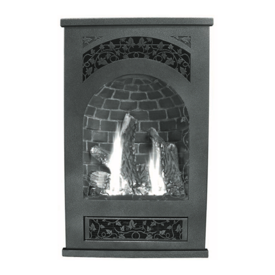
Haven
D I R E C T V E N T F I R E P L A C E
B Y : S H E R W O O D I N D U S T R I E S L T D
FOR YOUR SAFETY
Do not store or use gasoline or
other flammable vapours and
liquids in the vicinity of this or any
other appliance.
50-1268
Advertisement
Table of Contents

Related Manuals for Enviro Haven Haven Direct Vent Fireplace


Summary of Contents for Enviro Haven Haven Direct Vent Fireplace
- Page 1 SHERWOOD INDUSTRIES IS AN ENVIRONMENTALLY RESPONSIBLE COMPANY. THIS MANUAL IS PRINTED ON RECYCLED PAPER. PLEASE KEEP THESE INSTRUCTIONS FOR FUTURE REFERENCE OWNER’S MANUAL WHAT TO DO IF YOU SMELL GAS • Open windows/extinguish any open flame. • Do not try to light any appliance. •...
-
Page 2: Safety Precautions
Safety Precautions FOR SAFE INSTALLATION AND OPERATION OF YOUR “ENVIRO” HEATER, PLEASE CAREFULLY READ THE FOLLOWING INFORMATION: • All ENVIRO gas-fired appliances must be installed in accordance with their instructions. Carefully read all the instructions in this manual first. Consult the building authority having jurisdiction to determine the need for a permit prior to commencing the installation. -
Page 3: Table Of Contents
Table of Contents Safety Precautions...2 Table of Contents...3 Codes And Approvals...4 Specifications...5 Dimensions...5 Rating Label Location...5 Operating Instructions...6 Pilot Lighting Instructions...6 Pilot Light...7 Blower speed...7 Air Shutter...7 Burner Lighting...8 Remote controls...8 Normal Sounds During Operation...8 Maintenance And Service...9 Routine Maintenance...9 Cleaning The Glass...9 Cleaning The Firebox...9 Replacing the Glass...9... -
Page 4: Codes And Approvals
After the unit has gone through the first burn, turn the unit off including the pilot, let the unit get cold then remove the glass door and clean it with a good gas fireplace glass cleaner, available at your local ENVIRO dealer. -
Page 5: Specifications
INSTALLATION OPTIONS: • Parallel to a wall or placed in a corner • Vertica venting WARNING: Operation of this heater when not connected to a properly installed and maintained venting system can result in carbon monoxide (CO) poisoning and possible death. IMENSIONS "... -
Page 6: Operating Instructions
Operating Instructions For Your Safety, Read Safety Precautions And Lighting Instructions Before Operating WARNING: IF YOU DO NOT FOLLOW THESE INSTRUCTIONS EXACTLY A FIRE OR EXPLOSION MAY RESULT, CAUSING PROPERTY DAMAGE, PERSONAL INJURY OF LOSS OF LIFE. ILOT IGHTING NSTRUCTIONS CAUTION: Hot while operating. -
Page 7: Pilot Light
Operating Instructions ILOT IGHT 1. Turn off the gas to the fireplace. If not recently done, remove the glass and let the unit air out for at least five (5) minutes to clear out any gas. Turn on gas to the heater. Leak test all joints with soapy water. -
Page 8: Burner Lighting
After the unit has gone through the first burn, turn the unit OFF, including the pilot, and let the unit get completely cold. Then remove the glass and clean it with a good gas fireplace glass cleaner, available at your local Enviro dealer. See M and M... -
Page 9: Maintenance And Service
Do not operate your fireplace with the glass front removed, cracked or broken. Removal and replacement of the glass from the door must be done by a licensed or qualified service person. The glass must be purchased from an ENVIRO dealer. Substitute materials will void the warranty. -
Page 10: Cleaning Decorative Surfaces
Maintenance And Service LEANING ECORATIVE URFACES Painted and porcelain faces should be wiped with a damp cloth periodically. If a plated face has been purchased, it should be unpacked/unwrapped carefully to avoid getting anything on the surface of the finish, including cleaners, polish and finger prints. It is important to note that fingerprints and other marks can leave a permanent stain on plated finishes. -
Page 11: Fuel Conversion
Maintenance And Service ONVERSION TO BE INSTALLED BY A QUALIFIED SERVICE AGENCY ONLY Please read and understand these instructions before installing. Warning: This conversion kit shall be installed by a qualified service agency in accordance with the manufacturer’s instructions and all applicable codes and requirements of the authority having jurisdiction. - Page 12 Maintenance And Service Convert the SIT gas valve: a) Remove the black protection cap from the HI/LO knob by hand shown in Figure 9. Loosen Tighten Figure 10: Removing valve screw. g) Re-attach the black protection cap that was removed in step a (Figure 9).
-
Page 13: Initial Installation
Initial Installation QUALIFIED INSTALLERS ONLY NTRODUCTION This section of the owner’s manual is for the use of qualified technicians only. Fireplace placement, hearths, facing, mantles, and venting terminations will be covered, as well as the gas and electric systems. There are several installation safety guidelines that must be adhered to. Please carefully read the safety precautions at the front of this manual. -
Page 14: Corner Installation
Initial Installation The framing boards may touch the top, side and back standoffs, but no insulation or other material can be placed between the frame and the standoffs. The gas line, 3⁄8 inch NPT, can be brought to either the right side, the left side, or the bottom of the fireplace. -
Page 15: Framing Mount Brackets
Initial Installation QUALIFIED INSTALLERS ONLY 18" (457mm) minimum to ceiling Figure 18. Raised Fireplace with Raised Hearth. Figure 17. Raised Fireplace with Floor Level Figure 19. Raised Fireplace with No Hearth. Hearth. RAMING OUNT RACKETS Back Tabs; bent up & screwed into the wood framing The Haven can be secured to the framing and Wood Framing... -
Page 16: Wall Finishes
Initial Installation INISHES Any of the four (4) different haven faces will allow for up to a 1” (25mm) thick finishing wall (example drywall and tile); see Figure 22 & 23. The wall may be finished up to the fireplace standoffs with combustible materials. -
Page 17: Mantle Clearances
Initial Installation QUALIFIED INSTALLERS ONLY ANTLE LEARANCES It is not necessary to install a mantle, but if one is desired it is important to follow the guidelines. Top of unit to horizontal framing: Top of unit to bottom of 31⁄2” (8.9 cm) mantle: Top of unit to bottom of 10”... -
Page 18: Vent Termination Restrictions
Initial Installation ERMINATION ESTRICTIONS Fixed Closed Openable Termination Cap Figure 27. Vent Termination Restrictions, refer to Table 3. Table 3: Vent termination clearances, refer to Figure 27. Letter Canadian Installation 12 in (30 cm) 12 in (30 cm) 12 in (30 cm)* 24 in (60 cm)* 18 in (45 cm)* 12 in (30 cm)*... -
Page 19: Fireplace Horizontal Vent Kit 50-1235
Initial Installation QUALIFIED INSTALLERS ONLY IREPLACE ORIZONTAL Please read and understand these instructions before installing. Failure to follow these instructions carefully could cause property damage or personal injury. KIT COMPONENTS: Qnty Description Horizontal direct vent termination cap Flue collar adapter Wall thimble 5’... -
Page 20: Other Approved Vent Parts
Initial Installation 9. Install the flex pipe assembly through the wall thimble, ensure that this portion of pipe slides through the outside wall far enough to connect onto the vent termination cap. 10. Apply a bead of Mill-Pac Black sealant to the top section of the Ø4” (10 cm) by 5” (12.5 cm) flue collar adaptor previously installed into the fireplace flue outlet. - Page 21 Initial Installation QUALIFIED INSTALLERS ONLY WARNING: Do not mix parts from different vent manufacturers’s systems. EXCEPTION TO WARNING: This product has been evaluated by Intertek for using a Direct Vent GS starting collar in conjunction with Secure Vent, Direct-Temp, and Ameri Vent Direct venting systems. Use of these systems with the Direct Vent GS starting collar is deemed acceptable and does not affect the Intertek WH listing of the appliance.
-
Page 22: Venting
Initial Installation ENTING This fireplace has been tested and certified for use with SIMPSON DURAVENT DIRECT VENT TYPE “GS” PIPE FOR GAS STOVES, SECURITY CHIMNEY’S SECURE VENT DIRECT VENT SYSTEM kits, AMERICAN METAL PRODUCTS AMERIVENT DIRECT and DIRECT-TEMP SELKIRK METALBESTOS. A 1”... -
Page 23: Vent Configurations And Restrictor Settings
Initial Installation QUALIFIED INSTALLERS ONLY ONFIGURATIONS AND Figures 33 shows the range of venting options, it shows possible vent configurations if the unit is top vented, for vertical and horizontal terminations, any layout that remains within the shaded area is acceptable. -
Page 24: Horizontal Termination
Initial Installation ORIZONTAL ERMINATION NOTES: 1. Horizontal pipes must not be level. For every 12 inches (305 mm) of horizontal travel (away from the stove), there should be at least 1⁄4 inch (6.4 mm) of vertical travel. Never allow the vent to run downward, as this could cause high temperatures or even present the possibility of a fire. -
Page 25: Vertical Termination
Initial Installation QUALIFIED INSTALLERS ONLY NOTE: For Simpson Duravent only, place a bead of Mil-Pac or Rutland No 78 Stove and Gasket Cement on the outer edge of the inner exhaust pipe (non-flared end). Push the pipe sections together, then twist about 1⁄4 turn, making sure the two sections are fully locked. - Page 26 Initial Installation STEP 5. Cut hole in the roof centered on the small hole placed in the roof from Step 2. The hole should be of sufficient size to meet minimum requirements for Clearance to Combustibles, as specified. Continue to assemble lengths of pipe and elbows necessary to reach from the ceiling support box up through the roof line.
- Page 27 Initial Installation QUALIFIED INSTALLERS ONLY plumber’s tape connected to wall strap Wall strap 45° elbows (x2) Figure 38: Use of Wall Straps. (4) Any occupied areas above the first floor, including closets and storage spaces, which the vertical vent passes through, must be enclosed.
-
Page 28: Electrical System For Thermostat
Initial Installation LECTRICAL YSTEM CAUTION: Label all wires prior to disconnection when servicing controls. Wiring errors can cause improper and dangerous operation. Verify proper operation after servicing. 20ft (6.1m) of bell wire is included with this unit. Determine the desired location of the thermostat or wall switch (if used). -
Page 29: Gas Line Connection And Testing
Initial Installation ONNECTION AND WARNING: Only persons licensed to work with gas piping may make the necessary gas connections to this appliance. GAS LINE CONNECTION This fireplace is equipped with a certified flexible pipe located on the right side of the unit. This •... -
Page 30: Secondary Installation
Secondary Installation PTIONAL NSTALLATION If the Haven is installed the burner and valve assemblies must be removed. If the Haven is not installed the fan can be installed through an access hole at the lower rear of the unit. Fan Control Black Black Temperature... -
Page 31: Optional Fan Kit Installation Through Front Of Haven
Secondary Installation 6. Re-install the screws for the back cover and the stand-off. 7. Remove the two (2) screws holding the control panel in place. Pull the panel out of the way. 8. Slide the snap switch in place under the holding tabs above the SIT valve (see Figure 47). 9. -
Page 32: Log Set And Ember Installation
Secondary Installation 6. Install the two (2) grommets; place a 8-32 x 3⁄4” bolt through each grommet then attach the bolt to the back cover using a 1⁄4” socket (see Figure 51) 7. Ensure the wiring harness is attached to the fan then hook the two (2) slots on the fan box over the grommets installed in the last step. - Page 33 A small amount on the bottom side of the logs is normal. Remove and replace the logs in the same manner described above. If new/more embers and rock wool are required, contact your nearest ENVIRO dealer. Never operate the fireplace with the glass door removed.
-
Page 34: Installation Of Steel Firebox Liner Or Optional Ceramic Firebox Liner
Secondary Installation NSTALLATION OF TEEL IREBOX NOTE: The ceramic liner is fragile and should be handled gently. Please ensure that it has not been damaged. Turn off the gas control knob and allow the unit to cool. Figure 57. Ceramic Liner Suport. 5. -
Page 35: Troubleshooting
Troubleshooting Problem Possible Cause The main burner does not The gas valve may not be on. ignite when called for. Thermostat is not calling for heat. Problem with gas valve. Spark will not light the pilot Defective piezo ignitor. after repeatedly pressing the spark ignitor. -
Page 36: Parts List - Components
Fan Controller - 115V Convection Blower - 115V Convection Blower Kit- 115V SIT Pilot 1⁄8” Tube with End Furrels (1 piece) Enviro Logo Gel Decal Blank Orifice #73 On/Off Remote Control Kit Programmable Wall Mounted Remote Control Dual Bulb Door Gasket - 10 feet (3.05m) Door, Glass, &... -
Page 37: Parts List - Options
Parts List - Options Referance Part Description Number Firebox Liner - Bankers Brown Brick Firebox Liner - Arizona Stucco Firebox Liner - Red Brick Firebox Liner - Steel Black Fireplace Horizontal Vent Kit - 5 Feet (1.52m) Fireplace Horizontal Vent Kit - 10 Feet (3.05m) Roma Cast Iron Front - Painted Black Roma Cast Iron Front - Antique Chestnut Roma Cast Iron Front - Antique White... -
Page 38: Parts Diagram - Components
Parts Diagram - Components... -
Page 39: Parts Diagram - Fascia
Parts Diagram - Fascia The Haven - Fascia May 2005... -
Page 40: Warranty
Sherwood Industries Ltd. offers a Limited Lifetime Warranty on this gas product. This Limited Lifetime Warranty covers the appliance for a period of seven years from the date of installation. This warranty applies only to the original owner in the original location. Covered under the lifetime warranty are the chassis and the heat exchanger. -
Page 41: Installation Data Sheet
Installation Data Sheet The following information must be recorded by the installer for warranty purposes and future reference. NAME OF OWNER: _________________________________________ ADDRESS: _________________________________________ _________________________________________ _________________________________________ PHONE:___________________________________ MODEL:___________________________________ SERIAL NUMBER:___________________________ DATE OF PURCHASE: _____________ DATE OF INSTALLATION:___________ � � NATURAL GAS (NAT) INLET GAS PRESSURE:_________in WC MAIN BURNER ORIFICE:__________# DMS PILOT ORIFICE #_________OR________in diam.
Need help?
Do you have a question about the Haven Haven Direct Vent Fireplace and is the answer not in the manual?
Questions and answers