Enterasys ROAMABOUT RBT-1602 Installation Manual
Antenna site preparation and installation guide
Hide thumbs
Also See for ROAMABOUT RBT-1602:
- Release notes (28 pages) ,
- Installation manual (56 pages)

Subscribe to Our Youtube Channel
Related Manuals for Enterasys ROAMABOUT RBT-1602


Summary of Contents for Enterasys ROAMABOUT RBT-1602
- Page 1 RoamAbout ® Wireless Networking RBT-4102 / RBT-1602 Wireless Access Point Antenna Site Preparation and Installation Guide P/N 9034254...
- Page 3 Elektrischer Gefahrenhinweis: Installationen sollten nur durch ausgebildetes und qualifiziertes Personal vorgenommen werden. Enterasys Networks reserves the right to make changes in specifications and other information contained in this document and its web site without prior notice. The reader should in all cases consult Enterasys Networks to determine whether any such changes have been made. The hardware, firmware, or software described in this document is subject to change without notice. IN NO EVENT SHALL ENTERASYS NETWORKS BE LIABLE FOR ANY INCIDENTAL, INDIRECT, SPECIAL, OR CONSEQUENTIAL DAMAGES WHATSOEVER (INCLUDING BUT NOT LIMITED TO LOST PROFITS) ARISING OUT OF OR RELATED TO THIS DOCUMENT, WEB SITE, OR THE INFORMATION CONTAINED IN THEM, EVEN IF ENTERASYS NETWORKS HAS BEEN ADVISED OF, KNEW OF, OR SHOULD HAVE KNOWN OF, THE POSSIBILITY OF SUCH DAMAGES. Enterasys Networks, Inc. 50 Minuteman Road Andover, MA 01810 © 2006 Enterasys Networks, Inc. All rights reserved. Part Number: 9034254 May 2006 ENTERASYS, ENTERASYS NETWORKS, ROAMABOUT, and any logos associated therewith, are trademarks or registered trademarks of Enterasys Networks, Inc., in the United States and other countries. All other product names mentioned in this manual may be trademarks or registered trademarks of their respective companies. Documentation URL: http://www.enterasys.com/support/manuals Documentacion URL: http://www.enterasys.com/support/manuals Dokumentation URL: http://www.enterasys.com/support/manuals...
-
Page 5: Table Of Contents
About This Guide Intended Audience ... vii Related Documents ... viii Getting Help ... viii Conventions Used in This Guide ...ix Chapter 1: Site Preparation Choosing Antennas for Wireless Network Configurations ... 1-2 Determining the Antenna Locations ... 1-3 Distances with Cables ... 1-3 Line of Sight ... - Page 6 Mounting the RoamAbout 5.3 and 5.8 GHz Omni-Directional Antennas ... 3-19 Mounting On a Mast ... 3-20 Mounting On a Wall ... 3-21 Mounting the RoamAbout 5.8 GHz Panel Antenna ... 3-22 Mounting the Antenna to a Wall ... 3-22 Mounting the Antenna to a Mast...
- Page 7 3-14 Attaching the 5.8 GHz Panel Antenna Bracket to the Antenna ... 3-27 3-15 Mounting RoamAbout 4.9 to 5.9 GHz Sector Panel Antenna — Wide Mast ... 3-29 3-16 Mounting RoamAbout 4.9 to 5.9 GHz Sector Panel Antenna—Narrow Mast... 3-30 3-17 Installing External Flaps for 4.9 to 5.9 GHz Sector Panel Antenna ...
- Page 8 A-14 802.11a/b/g Range Extender Omni-Directional Antenna Specifications ...A-16 A-15 Pigtail Connection Specification ...A-17 A-16 RBTES-L200 Cable Specification...A-18 A-17 RBTES-L400 Cable Specifications ...A-19 A-18 RBTES-L600 Cable Specifications ...A-20 A-19 Lightning Protector Specifications ...A-21...
-
Page 9: About This Guide
This guide describes the requirements for the successful installation of the RoamAbout indoor and outdoor antennas used in a RoamAbout wireless network. A RoamAbout wireless network consists of RoamAbout wireless products that use an 802.11 a/b/g compliant radio. Electrical Hazard: Only qualified personnel should perform installation procedures. Riesgo Eléctrico: Solamente personal calificado debe realizar procedimientos de instalacion. Elektrischer Gefahrenhinweis: Installationen sollten nur durch ausgebildetes und qualifiziertes Personal vorgenommen werden. Intended Audience The RoamAbout outdoor antennas must be installed by an antenna installation professional who can determine, provide, and install the necessary support structure and grounding system. The antenna installation professional should be licensed or certified in accordance with local regulations. Chapter 1 contains information for a sales engineer or site evaluator to determine the type of ... -
Page 10: Related Documents
The device history (for example, if you have returned the device before, or if this a recurring problem) • Any previous Return Material Authorization (RMA) numbers viii About This Guide http://www.enterasys.com/services/support/ 1-800-872-8440 (toll-free in U.S. and Canada) or 1-978-684-1000 For the Enterasys Networks Support toll-free number in your country: http://www.enterasys.com/services/support/contact/ support@enterasys.com To expedite your message, please type [RoamAbout] in the subject line. -
Page 11: Conventions Used In This Guide
Conventions Used in This Guide Conventions Used in This Guide The following conventions are used in this guide. Note: Calls the reader’s attention to any item of information that may be of special importance. Caution: Contains information essential to avoid damage to the equipment. Precaución: Contiene información esencial para prevenir dañar el equipo. Achtung: Verweißt auf wichtige Informationen zum Schutz gegen Beschädigungen. - Page 12 Conventions Used in This Guide x About This Guide...
-
Page 13: Chapter 1: Site Preparation
Warning: Site prerequisites should be verified by a person familiar with national codes, local electrical codes, and with other regulations governing this type of installation. Enterasys Networks, its channel partners, resellers, and distributors assume no liability for personal injury, property damage, or violation of government regulations that may arise from failing to comply with the instructions in this guide. -
Page 14: Choosing Antennas For Wireless Network Configurations
Choosing Antennas for Wireless Network Configurations Choosing Antennas for Wireless Network Configurations The type and number of antennas that you need depend on the configuration of your wireless network. Table configurations. Table 1-1 Antennas for Wireless Network Configurations Wireless Network Configuration LAN-to-LAN Point-to-Point (RBT-4102 only) LAN-to-LAN Point-to-Multipoint (RBT-4102 only) Wireless Infrastructure 1-2 Site Preparation 1‐1 lists the general type of antenna to use for various wireless network Description This is a wireless link between two APs that connects two separate wired LANs. -
Page 15: Determining The Antenna Locations
Determining the Antenna Locations The following factors determine the locations where you can place the antennas relative to one another and the distances between them: • Type of antennas. The RoamAbout antennas are described in Antenna Models on page 1‐9. • Length of cable connecting the antenna to the AP. • Data rate required. • In a LAN‐to‐LAN network, the distance between the buildings. • Obstructions in the signal path. • In a wireless infrastructure network, the area around the antenna where clients need to communicate with the AP. Typically, the RoamAbout directional and omni‐directional antennas are installed on rooftops. The directional antenna can also be installed on the side of a building. The following sections describe the factors that affect the range of the antennas. Distances with Cables Table 1‐2 lists the distances for the RBT‐4102, RBT‐4102‐EU, and the RBT‐4102 ‐BG. The distances include the cables at both ends. For every 6 dBi of cable loss, divide the distance by two. For every 10 dBi of cable loss, divide the distance by three. Notes: • Be sure to calculate the cable loss at both ends, and include the pigtails. •... - Page 16 Determining the Antenna Locations Table 1-2 Outdoor Distance Matrix Between Antennas (RBT-4102 LAN to LAN/MultiPoint) Antenna 5.7 - 5.8 RBTES-AH-P23M/M0M (23 dBI to 10 dBI) For use in North America only. 5.4 - 5.7 RBTES-AW-S1590M (15 dBi to 15 dBI) Based on ETSI Standards.
-
Page 17: Line Of Sight
Determining the Antenna Locations Line of Sight The shape of the radio beam, defined as the Fresnel Zone, is widest in the middle. The Fresnel Zone is shown as the gray area between the antennas in Figure 1‐1. The exact shape and width of the Fresnel Zone is determined by the distance between the antenna and frequency of the radio signal. The radius of the radio beam, shown as the lower half of the Fresnel Zone, is the distance from the center of the beam outward in any direction. The length of the radius is not based on the data rate and the type of antenna. Figure 1-1 Fresnel Zone and Line of Sight Clearance If a significant part of the Fresnel Zone is obstructed, a portion of radio energy is lost, resulting in reduced performance. For optimal performance, ensure that the antenna products you choose, in combination with the height of the antenna installation above ground, provide sufficient clearance to allow your antenna installation to cover the distance between the two sites. Obstacles within the line of sight can significantly reduce the distance and performance. Obstructions include neighboring buildings, trees, and power lines, as shown in Figure 1‐2. RoamAbout Antenna Site Preparation and Installation Guide 1-5... -
Page 18: Potential Obstacles To Line Of Sight (Not To Scale)
Determining the Antenna Locations Figure 1-2 Potential Obstacles to Line of Sight (not to scale) 1-6 Site Preparation... -
Page 19: Other Factors That Can Reduce Antenna Range
Determining the Antenna Locations Other Factors That Can Reduce Antenna Range Large reflecting surfaces that are parallel or partly perpendicular to the radio signal cause reflections of the radio signal (see Figure 1‐3). Examples of reflecting surfaces are buildings with low‐emissivity (low‐e) glass, crowded parking lots, water, moist earth, moist vegetation, and above‐ground power or telephone lines. Because surrounding objects, such as trees, power lines, and other antennas, seriously reduce efficiency of the antenna, it is very important to mount the antenna as high and clear of obstacles as possible. Figure 1-3 Large Reflecting Surfaces RoamAbout Antenna Site Preparation and Installation Guide 1-7... -
Page 20: Additional Location Requirements
Determining the Antenna Locations Additional Location Requirements This section describes other requirements to meet before installing the RoamAbout outdoor antennas. • Lightning Protection A lightning rod must be placed close to the antenna mast or wall bracket. This is required to protect the antenna from direct lightning strikes. • Grounding System Direct earth grounding of the antenna and the Lightning Protector is necessary to protect the installation from lightning and the build‐up of static electricity. The wireless device and the Lightning Protector must be connected to the same earth ground using separate grounds. The antenna and the mounting structure require separate grounds to the same earth ground, using an equipotential bonding conductor. Check with a certified antenna installer, or local electrician, to make sure the antenna is properly grounded. Ensure that the cable between the antenna and Lightning Protector is at least 0.9 meters (3 feet) away from high‐voltage or high‐current cable. • Antenna Height If you are mounting the antenna on a roof, it must be at least 1.5 meters (5 feet) above the roof line. If you are mounting the directional antenna to a wall of a building, it must be high enough to achieve a clear line of sight. Mounting an omni‐directional antenna to the side of a building can cause signal reflection and reduce distance. Note: The installer is responsible for local building codes. • AP placement The AP should be located indoors, and connected to the outdoor antenna using the shortest ... -
Page 21: Antenna Models
Antenna Models The following sections provide brief descriptions of these antennas. Refer to Chapter installation instructions, and Appendix • Table 1‐3 lists the RBT‐4102 indoor/outdoor antenna models. • Table 1‐4 lists the RBT‐4102 indoor only antenna model. • Table 1‐5 lists the RBT‐1602 indoor/outdoor antenna models. Table 1-3 RBT-4102 Indoor/Outdoor Antenna Options Model Number RBTES-BG-M08M RBTES-BG-P18M RBTES-BG-S1490M RBTES-AM-M10M RBTES-AH-M10M RBTES-AH-P23M RBTES-AW-S1590M Table 1-4 RBT-4102 Indoor Only Antenna Option Model Number RBT4K-AG-IA A for antenna specifications. Name RoamAbout 2.4 GHz 8 dBi Omni-directional Base Station Antenna RoamAbout 2.4 GHz Directional Panel... -
Page 22: Rbt-1602 Indoor/Outdoor Antenna Options
Antenna Models Table 1-5 RBT-1602 Indoor/Outdoor Antenna Options Model Number RBTES-BG-S06180 RBTES-BG-S07120 RBTES-BG-S1060 RBTES-AW-S1460 RBTES-AW-S12120 RBTES-AW-S10180 1-10 Site Preparation Name RoamAbout 2.4 GHz 6 dBi Sector Panel Antenna RoamAbout 2.4 GHz 7 dBi Sector Panel Antenna RoamAbout 2.4 GHz 10 dBi Sector Panel Antenna RoamAbout 5.1-5.9 GHz 14.5 dBi Sector Panel Antenna... -
Page 23: Cable Options
25 feet (7.6 meters) LMR600 50 feet (15.24 meters) LMR400 50 feet (15.24 meters) LMR600 75 feet (22 meters) LMR400 Note: Enterasys Networks does not recommend using this cable due to the loss factor. Description Reverse-N Male on both ends Male connector housing and male center contact. -
Page 24: Roamabout Pigtail Connection Options
RoamAbout Pigtail Connection Options RoamAbout Pigtail Connection Options The RoamAbout Pigtail Connection is a proprietary cable used to connect the RoamAbout Radio Card to a RoamAbout antenna system. One end of the cable has a proprietary MC‐card connector that connects to the RoamAbout Radio Card. The other end has a reverse polarity N‐Type male or female connector to connect to your antenna cabling system. Select the connector gender based on your cable configuration. Table 1‐8 lists the RoamAbout pigtail options. Table 1-8 Pigtail Options Model Number RBT4K-AG-PT20F RBTB-AG-PT20M 1-12 Site Preparation Description • Reverse SMA Female connector. • Reverse-N Female - Female connector housing and female center contact. -
Page 25: Contacting An Antenna Installation Company
Contacting an Antenna Installation Company Have an antenna installation professional install the outdoor antennas. The antenna installer provides the expertise to properly install, secure, and ground your antenna. The following checklists describe tasks that the installer may need to perform. Note: The antenna installation professional should be licensed or certified in accordance with local regulations. Lightning Protection √ Determine the mounting location for the lightning rod (positioned near the antenna). √ Ensure an earth ground location for the antenna structure and Lightning Protector. Mounting Requirements √ Determine the type of mounting that is required (tripod, wall mount, etc.). √ Determine the guy wires needed. Typically, three guy wires are needed for each 3 meter (10 foot) section of the mast; for example, 6 meters (20 feet) of mast requires six guy wires. Line of Sight √ Determine the mounting location for the antenna. -
Page 26: Installation Requirements
Contacting an Antenna Installation Company Installation Requirements √ Determine the best location for the AP. √ Determine the length of cable required from the antenna to the AP. √ Ensure the location has an accessible Ethernet connection. √ Determine the distance between buildings. You may need to provide the following distances when contacting the antenna installation company: Distance between the antennas (building-to- building network): Coverage area required (wireless infrastructure network configuration): Height of building A: Height of building B: All possible obstacles that can interfere with the defined radius. -
Page 27: Chapter 2: Ap Placement And Configuration
This chapter provides information for the antenna installer and network manager to determine where to place the RoamAbout AP and Lightning Protector. Determining the Location of the AP The RoamAbout AP connects to a Lightning Protector with a 51‐centimeter (20‐inch) cable. The Lightning Protector connects to the outdoor antenna with a standard 6.1‐meter (20‐foot), 7.6‐meter (25‐foot), 15.24‐meters (50‐foot), or a 22‐meter (75‐foot) low‐loss cable. A longer cable will decrease the distance achievable between antennas. The ideal location to install your RoamAbout AP and Lightning Protector must satisfy the following requirements: • The location must be indoors to protect the AP from extreme weather conditions, excessive heat and humidity, and to keep the unit free from vibration and dust. • The Lightning Protector and antenna mast must be connected to the same earth ground (using separate grounds), as the AC wall outlet ground using an equipotential bonding conductor. • The location must provide a connection to the network backbone via an Ethernet LAN cable going to a hub, bridge, or directly into a patch panel. • The location must be close to where the low‐loss antenna cable will enter the building. The low‐loss cable connecting the antenna to the Lightning Protector should not exceed 75 feet in length for 2.4 GHz, or 50 feet in length for 5 GHz, due to the distance reduction with longer cables. AP Placement and Configuration RoamAbout Antenna Site Preparation and Installation Guide 2-1... -
Page 28: Overview Of Connecting Cables To The Access Point
Overview of Connecting Cables to the Access Point Overview of Connecting Cables to the Access Point Before cabling the AP, you should install the AP to a wall or ceiling. For detailed hardware installation procedures, refer to the RoamAbout Wireless Access Point Hardware Installation Guide specific to your AP. RBT-4102 Figure 2‐1 illustrates the RBT‐4102 to antenna cable configurations. Table antenna cable components. Table Figure 2-1 RBT-4102 Installation Overview 2-2 AP Placement and Configuration 2‐2 lists the RBT‐4102 installation components. Switch 2‐1 lists the RBT‐4102 to ... -
Page 29: Rbt-4102 To Antenna Installation Components
Table 2-1 RBT-4102 to Antenna Installation Components Component Antenna connector (Reverse-N Male) Cable from antenna to Lightning Protector (Reverse-N Female on both ends) Lightning protector (Reverse-N Male on both ends) Lightning Protector ground terminal Cable from Lightning Protector to AP pigtail (Reverse-N Female on both ends) AP pigtail (Reverse-N Male) AP pigtail (Reverse-N Female) Table 2-2 RBT-4102 Installation Components... -
Page 30: Rbt-1602 Installation Overview
Overview of Connecting Cables to the Access Point RBT-1602 Figure 2‐2 illustrates the RBT‐1602 to antenna cable configurations. Table antenna cable components. Table Figure 2-2 RBT-1602 Installation Overview OUTDOOR INDOOR Switch Table 2-3 RBT-1602 to Antenna Installation Components Component Antenna Pole Antenna connector Cable Lightning protector Lightning protector ground terminal AP pigtail connector to AP external antenna connector 2-4 AP Placement and Configuration 2‐4 lists the RBT‐1602 installation components. -
Page 31: Rbt-4102
Table 2-4 RBT-1602 Installation Components Component RBT-1602 Access Point RBT-1602 Access Point mounting bracket (dual/redundant 10/100 port) Connection to switch (dual/redundant 10/100 port) To set up the RoamAbout AP, perform the following steps: Remove the plastic cap from the radio connector(s) and connect it to the pigtail cable. Connect the AP pigtail to the antenna as appropriate for your cable configuration. Refer to Connecting the Antenna Cables on page 3‐34. Connect the Ethernet cable from the AP to the AP connector on the power adapter. Record the AP’s MAC address (located on the side of the unit). Record the radio cards’ MAC addresses. If you are using PoE, connect the Ethernet cable to your PoE switch. If your switch does not support PoE, you will need to provide an inline power injector, or use the local power option on the RBT‐4102. Overview of Connecting Cables to the Access Point RoamAbout Antenna Site Preparation and Installation Guide 2-5... - Page 32 Overview of Connecting Cables to the Access Point 2-6 AP Placement and Configuration...
-
Page 33: Chapter 3: Antenna Installation
This chapter provides the information necessary for a professional antenna installer to install the RoamAbout antennas. Electrical Hazard: Antennas should only be installed by a qualified antenna installer. The antenna installation professional should be licensed or certified in accordance with local regulations. Do not install the antenna in wet, windy, icy, or otherwise unsafe weather conditions. Peligro de descarga eléctrica: la colocación de la antena debe realizarla un instalador de antenas calificado y con las licencias correspondientes en las regulaciones locales. -
Page 34: Installation Overview
Installation Overview Installation Overview The installation process is summarized in the following steps. The following sections in this chapter provide additional details. Make sure the APs are mounted and configured as specified in Chapter Plan and implement a grounding system that meets local electrical codes and safety standards. Install the RoamAbout Lightning Protector. Provide and install an antenna support structure as necessary. Make sure that the support structure is connected to the grounding system. Connect the exposed metal connectors of the low‐loss antenna cable to the grounding system. Mount the antenna to the support structure. Connect the antenna cables. Route and connect the low‐loss antenna cable to the RoamAbout Lightning Protector that has been installed indoors. Connect the cable assembly from the RoamAbout radio card in the AP to the Lightning Protector. 10. After verifying that the communications link is fully operational, secure all cables and use weatherproofing tape to seal all outdoor connectors. 3-2 Antenna Installation... -
Page 35: Grounding System
Grounding System Direct earth grounding of the antenna and the Lightning Protector is necessary to protect the installation from lightning and the build‐up of static electricity. Caution: The antenna mast, RoamAbout AP, and Lightning Protector must be connected to the same earth ground (with separate grounds), using an equipotential bonding conductor. A good electrical connection should be made to one or more ground rods using at least a 10AWG ground wire and non-corrosive hardware. -
Page 36: Lightning Protector Installation
Lightning Protector Installation Lightning Protector Installation Lightning protection is designed to protect people, property, and equipment by providing a path to the ground whenever lightning strikes your antenna installation. The RoamAbout Lightning Protector is an indispensable part of such a grounding system to protect your electronic equipment from transients and/or electrostatic discharges at the antenna. For optimal protection, locate the RoamAbout Lightning Protector as follows: • As close as possible to the point where the antenna cable enters the building. • To allow connection to the same grounding system as the RoamAbout AP and the antenna mast. Figure 3‐1 illustrates how to install the Lightning Protector. Table components. Figure 3-1 Lightning Protector Installation Table 3-1 Lightning Protector Mounting Components Component Hex nut Lock washer Ring terminal Lightning protector 3-4 Antenna Installation 3‐1 lists the mounting ... - Page 37 To install the RoamAbout Lightning Protector, perform the following steps: Determine a suitable location for the Lightning Protector as described in Chapter Use lock washer and hex nut to secure ring‐terminal to the longer of the threaded ends of the Lightning Protector. Connect ground‐wire to ring terminal. Connect the longer threaded end of the protector to a Reverse‐N Female cable connected to a RoamAbout Access Point. Connect the shorter threaded end of the protector to a Reverse‐N Female cable connected to the antenna. Caution: To avoid damage to the RoamAbout equipment, always install the RoamAbout Lightning Protector between the outdoor antenna installation and the RoamAbout AP or other computing device connected to the outdoor antenna. Precaución: para evitar daños a los equipos RoamAbout, debe asegurarse de instalar el pararrayos RoamAbout Lightning Protector entre la antena para exteriores y el RoamAbout AP o cualquier otro dispositivo electrónico conectado a la antena.
-
Page 38: Mounting The Antenna
Mounting the Antenna Mounting the Antenna This section includes requirements and mounting guidelines for the RoamAbout outdoor antennas. Each antenna mounting section contains an illustration of the antenna, component description, and a mounting procedure. Selecting a Mast Note: You must supply your own mast on which to mount a RoamAbout antenna. RoamAbout antennas do not come with masts. To minimize the influence of obstacles, signal interference or reflections, install the antenna at least 2 meters (6 feet) away from all other antennas. If you need to mount multiple antennas on a single mast, alternate the mounting of directional antennas for vertical and horizontal polarization. In subfreezing conditions, the communications link could fail if an antenna is exposed to ice buildup or covered with snow. The mast must satisfy the following requirements: •... -
Page 39: Antenna Polarization
Antenna Polarization It does not matter what type of polarization you choose for your RoamAbout antennas as long as the antenna at one end of the communications link is mounted in the same plane as the antenna at the other end. Vertical polarization is standard for the RoamAbout 14 dBi directional antenna. To minimize the influence of cross‐talk between antennas, you might need to mount the antenna for horizontal polarization when: • Multiple antennas are mounted on the same antenna mast. • The wireless link transmissions cross another radio beam from a neighboring installation. RoamAbout Antenna Site Preparation and Installation Guide 3-7 Mounting the Antenna... -
Page 40: Mounting Roamabout 2.4 Ghz 8 Dbi Omni-Directional Base Station Antenna
Mounting the Antenna Mounting RoamAbout 2.4 GHz 8 dBi Omni-Directional Base Station Antenna You can mount the RoamAbout 2.4 GHz omni‐directional base station antenna (part number RBTES‐BG‐M08M) on a mast. The RoamAbout 2.4 GHz omni‐directional base station antenna kit includes the following hardware: • One mounting bracket • One U‐bolt • Two hex nuts • Two spring lock washers • Two flat washers Figure 3‐2 illustrates how to mount the RoamAbout omni‐directional base station antenna on a mast in a horizontal polarization mode. Table Figure 3-2 Mounting the 2.4 GHz Omni-Directional Antenna to a Mast Table 3-3 RoamAbout Omni-Directional Base Station Antenna Mounting Components Component Mount... - Page 41 To mount the omni‐directional base station antenna to a mast, perform the following steps: With the mount situated so that the arrows stamped on its toothed surface face up, insert the top of the antenna through the center hole in the mount. Slide the mount down the antenna until it is seated securely around the base of the antenna. Note: The mount’s center hole is tapered to match the taper of the antenna base. The antenna will thus fit snugly into the mount’s center hole. Tighten the set screws on the sides of the mount until tight. Place the U‐bolt around the mast. Insert the U‐bolt ends through the screw holes on the side flange of the mount. Insert the flat and spring lock washers over the U‐bolt threaded ends. Thread a hex nut on each end of the U‐bolt until each nut is finger tight. Position antenna at desired location along mast and tighten both hex nuts using an Allen wrench. After mounting the antenna, connect the antenna cables as described in “Connecting the Antenna Cables” on page 3‐34. RoamAbout Antenna Site Preparation and Installation Guide 3-9 Mounting the Antenna...
-
Page 42: Mounting The Roamabout 2.4 Ghz Directional Antenna
Mounting the Antenna Mounting the RoamAbout 2.4 GHz Directional Antenna You can mount the RoamAbout 2.4 GHz directional antenna (part number RBTES‐BG‐P18M) on a wide or narrow mast. Notes: Wide masts have dimensions of 1.25 to 2.5 inches [1.66 to 2.88 Outside Dimensions (OD)] for Schedule 40 pipe. Narrow masts have dimensions of less than 1.25 inches (1.66 OD) for Schedule 40 pipe. The RoamAbout 2.4 GHz directional antenna kits include the following hardware: •... - Page 43 Table 3-4 RoamAbout 2.4 GHz Directional Antenna Wide Mast Mounting Component Component Channel washer Flat washer and nut Antenna tilt angle adjuster Mast (user supplied) To mount the RoamAbout 2.4 GHz directional antenna to a wide mast, perform the following steps: Loosen the nuts on the open end of the U‐bolt until you can swing the notched end of the bracket (side with the channel washer) off of the U‐bolt. Insert the U‐bolt around the mast. If necessary, to widen the opening between the mounting brackets, turn the nuts for the mounting bracket near the closed end of the U‐bolt so that bracket moves towards the closed end of the U‐bolt. Swing the notched end of the bracket (nearest the open end of the U‐bolt) onto the U‐bolt. Tighten the nuts until the brackets grip the mast snugly. Turn the tilt angle adjuster to the angle at which you want to mount the antenna. Repeat steps 1 through 5 to attach the second U‐bolt mount to the mast. Connect the antenna to the screws in the middle of the tilt angle adjusters on each U‐bolt. After mounting the antenna, connect the antenna cables as described in “Connecting the Antenna Cables” on page 3‐34. RoamAbout Antenna Site Preparation and Installation Guide 3-11 Mounting the Antenna...
-
Page 44: Mounting On A Narrow Mast
Mounting the Antenna Mounting On a Narrow Mast Figure 3‐4 illustrates how to mount the RoamAbout 2.4 GHz directional antenna on a narrow mast. Table 3‐5 lists the narrow mast mounting components. Figure 3-4 Mounting the RoamAbout 2.4 GHz Directional Antenna on a Narrow Mast Table 3-5 RoamAbout 2.4 GHz Directional Antenna Narrow Mast Mounting Components Component Antenna (RBTES-BG-P18M) U-bolts Bolt to attach antenna to mount Mounting bracket Channel washer Flat washer and nut... - Page 45 To mount the RoamAbout 2.4 GHz directional antenna to a narrow mast, perform the following steps: Remove the nuts, flat and channel washers from the open end of the U‐bolt. Remove the bracket nearest to the open end of the U‐bolt. Insert the U‐bolt around the mast. Reverse the orientation of the bracket that you removed so that it is on the U‐bolt in the same orientation as the other bracket. (That is, with the convex side of the bracket facing the closed end of the U‐bolt and the concave side of the U‐bolt facing the open end of the U‐bolt.) Replace the nuts, flat and channel washers on the ends of the U‐bolt. Note: Install the channel washer on the notched side of the bracket. Tighten the nuts until the brackets grip the mast snugly. Turn the tilt angle adjuster to the angle at which you want to mount the antenna. Repeat steps 1 through 7 to attach the second U‐bolt mount to the mast. Connect the antenna to the screws in the middle of the tilt angle adjusters on each U‐bolt. After mounting the antenna, connect the antenna cables as described in “Connecting the Antenna Cables” on page 3‐34. RoamAbout Antenna Site Preparation and Installation Guide 3-13 Mounting the Antenna...
-
Page 46: Mounting The Roamabout 2.4 Ghz Sector Panel Antenna
Mounting the Antenna Mounting the RoamAbout 2.4 GHz Sector Panel Antenna You can mount the RoamAbout 2.4 GHz sector panel antenna (part number RBTES‐BG‐S1490M) to a wide or narrow mast. Notes: Wide masts have dimensions of 1.25 to 2.5 inches [1.66 to 2.88 Outside Dimensions (OD)] for Schedule 40 pipe. Narrow masts have dimensions of less than 1.25 inches (1.66 OD) for Schedule 40 pipe. The RoamAbout 2.4 GHz sector panel antenna kit includes the following hardware: •... -
Page 47: Mounting Sector Panel Antenna - Narrow Mast
Figure 3-6 Mounting Sector Panel Antenna - Narrow Mast Table 3-6 RoamAbout 2.4 GHz Sector Panel Mast Mounting Components Component Antenna (RBTES-BG-S1490M) U-bolt Bolt to attach antenna to mount Mounting bracket Channel washer Flat washers and nuts Antenna tilt angle adjuster Mast (user supplied) RoamAbout Antenna Site Preparation and Installation Guide 3-15 Mounting the Antenna... -
Page 48: Mounting The Roamabout 2.4 Ghz 6 Dbi 180 Degree Sector Panel Antenna (Rbt-1602 Only)
Mounting the Antenna Mounting the RoamAbout 2.4 GHz 6 dBi 180 Degree Sector Panel Antenna (RBT-1602 only) You can mount the RoamAbout 2.4 GHz 6 dBi sector panel antenna (part number RBTES‐BG‐S06180) to a pole or a solid wall. Caution: The external antenna must be installed at least 20-cm from the access point. Caution: Installation of external antennas must be performed by qualified service personnel only. Caution: On 802.11a antennas, the metal plate attached to the back of the antenna is a reflector plate. -
Page 49: Rbt-1602 Antennas
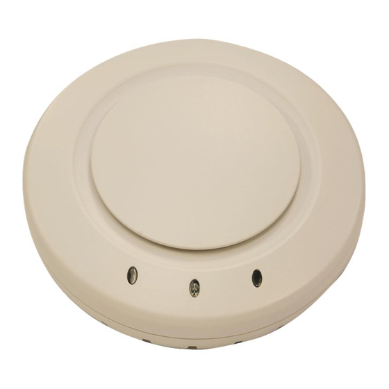
Figure 3-7 RBT-1602 Antennas 1. RBTES‐BG‐S1060 2. RBTES‐BG‐S07120 3. RBTES‐BG‐S06180 4. RBTES‐AW‐S10180, RBTES‐AW‐S12120, RBTES‐AW‐S1460 Figure 3‐8 illustrates how to mount the 2.4 GHz 6 dBi sector panel antenna. Table mounting components. Figure 3-8 Mounting 2.4 GHz 6 dBi Sector Panel Antenna Table 3-7 RoamAbout 2.4 GHz 6 dBi Sector Panel Mast Mounting Components Component Pole Mounting bracket RoamAbout Antenna Site Preparation and Installation Guide 3-17 Mounting the Antenna 1. Mounting clamps 2. Mounting brackets... -
Page 50: Pole Installation
Mounting the Antenna Table 3-7 RoamAbout 2.4 GHz 6 dBi Sector Panel Mast Mounting Components (continued) Component Clamp Connector Pole Installation To mount the antenna on a pole, perform the following steps: Attach the pole‐mounting brackets to the antenna: Place one of the pole‐mounting brackets against the back of the antenna, and align the screw holes over two screw holes in the antenna. Make sure the large slot in the bracket is not behind the antenna. If it is, turn the bracket around. b. Insert two of the screws in the mounting kit into the antenna screw holes. Place a lock washer and nut on the other end of each screw, and tighten to fasten the bracket to the antenna. d. Repeat for the other bracket. Place the mounting clamps on the pole. If you cannot slide the clamps over the top of the pole, completely loosen the clamps until they come apart, then refasten them after placing them around the pole. Align the clamps around the cutouts in the sides of the pole‐mounting brackets, then tighten the clamps to fasten the antenna in place. Solid Wall Installation To attach the antenna to a wall, perform the following steps: Prepare the screw holes as follows: Hold the antenna (or mounting plate) in the desired installation location and mark the ... -
Page 51: Mounting The Roamabout 2.4 Ghz 7 Dbi 120 Degree Sector Panel Antenna
Mounting the RoamAbout 2.4 GHz 7 dBi 120 Degree Sector Panel Antenna Part number: RBTES‐BG‐S07120 Refer to “Mounting the RoamAbout 2.4 GHz 6 dBi 180 Degree Sector Panel Antenna (RBT‐1602 only)” on page 3‐16 for antenna information and installation instructions. Mounting the RoamAbout 2.4 GHz 10 dBi 60 Degree Sector Panel Antenna Part number: RBTES‐BG‐S1060 Refer to “Mounting the RoamAbout 2.4 GHz 6 dBi 180 Degree Sector Panel Antenna (RBT‐1602 only)” on page 3‐16 for antenna information and installation instructions. Mounting the RoamAbout 5.1-5.9 GHz 10.8 dBi 180 Degree Sector Panel Antenna Part number: RBTES‐AW‐S10180 Refer to “Mounting the RoamAbout 2.4 GHz 6 dBi 180 Degree Sector Panel Antenna (RBT‐1602 ... -
Page 52: Mounting On A Mast
Mounting the Antenna Mounting On a Mast Figure 3‐9 illustrates how to mount the RoamAbout 5.3 and 5.8 GHz omni‐directional antennas on a mast. Table 3‐8 lists the mast mounting components. Figure 3-9 Mast Mounting the 5.3 and 5.8 GHz Omni-Directional Antenna Table 3-8 5.3 and 5.8 GHz Omni-Directional Antenna Mast Mounting Components Component Antenna (RBTES-AH-M10M) or (RBTES-AM-M10M) Mounting bracket Lock washer and hex nut for securing antenna to mount Clamps Mast (user supplied) To mount a 5.3 or 5.8 GHz omni‐directional antenna to a mast, perform the following steps:... -
Page 53: Mounting On A Wall
Note: Do not allow the top surface of the bracket to exceed the top of the mast. After mounting the antenna, connect the antenna cables as described in “Connecting the Antenna Cables” on page 3‐34. Mounting On a Wall Figure 3‐10 illustrates how to mount the RoamAbout 5.3 and 5.8 GHz omni‐directional antennas on a wall. Table 3‐9 lists the wall mounting components. Figure 3-10 Wall Mounting the 5.3 and 5.8 GHz Omni-Directional Antenna Table 3-9 5.3 and 5.8 GHz Omni-Directional Antenna Wall Mounting Components Component Antenna (RBTES-AH-M10M) or (RBTES-AM-M10M) Mounting bracket... -
Page 54: Mounting The Roamabout 5.8 Ghz Panel Antenna
Mounting the Antenna Position the long end of the mounting bracket containing screw holes flat against the wall where you want to fasten it. Fasten the bracket to wall with a screw in each of the screw holes. Note: Screws for mounting the bracket to the wall do not come with the antenna kit. After mounting the antenna, connect the antenna cables as described in “Connecting the Antenna Cables” on page 3‐34. Mounting the RoamAbout 5.8 GHz Panel Antenna You can mount the RoamAbout 5.8 GHz panel antenna (RBTES‐AH‐P23M) to a wall or a mast. The RoamAbout 5.8 GHz panel antenna kit includes the following hardware: • One antenna bracket • Two mast brackets • Two carriage bolts •... -
Page 55: Attaching Antenna Bracket To Roamabout 5.8 Ghz Panel Antenna
Obtain the proper screws to secure the antenna bracket to this wall surface. Note: This antenna does not ship with screws for attaching the antenna bracket to a wall. Attaching the Antenna Bracket to the Antenna Figure 3‐11 illustrates how to attach the antenna bracket to the 5.8 GHz panel antenna. Table lists the components for this procedure. Figure 3-11 Attaching Antenna Bracket to RoamAbout 5.8 GHz Panel Antenna Table 3-10 RoamAbout 5.8 GHz Panel Antenna Bracket Mounting Components Component Antenna bracket Antenna (RBTES-AH-P23M) -
Page 56: Mounting The Roamabout 5.8 Ghz Panel Antenna To A Wall
Mounting the Antenna Situate the antenna bracket against the antenna, so that the end against the antenna pivots in the same plane as the desired polarization. For example, if using vertical polarization, this antenna bracket end should pivot up and down. If using horizontal polarization, this antenna bracket end should pivot from side‐to‐side. Use the four (yellow) hex nuts, to secure the antenna bracket to the back of the antenna. Rotate the pivot of the bracket end attached to the antenna to adjust the antenna position. Lock bracket in desired position by tightening nuts on either side of bracket end with wrenches. Mounting the Antenna to a Wall Figure 3‐12 illustrates how to attach the 5.8 GHz panel antenna to a wall. Table components for this procedure. Figure 3-12 Table 3-11 RoamAbout 5.8 GHz Panel Antenna Wall Mounting Components Component Antenna (RBTES-AH-P23M) Antenna bracket Wall Screw holes in wall Screws for attaching antenna to the wall (user supplied) 3-24 Antenna Installation Mounting the RoamAbout 5.8 GHz Panel Antenna to a Wall... -
Page 57: Mounting The Antenna To A Mast
To attach the antenna bracket to the wall, perform the following steps: Place the antenna bracket against the wall where you want to attach antenna. Secure the antenna bracket to the wall with screws (user provided) in the four screw holes in the pivot bracket. Rotate the pivot of the bracket end attached to the wall to adjust the antenna position. Lock bracket end in desired position by tightening nuts on either side of bracket end with wrenches. Mounting the Antenna to a Mast Mounting the antenna to a mast requires the following major steps: • Attaching the mast brackets to the antenna bracket • Attaching the antenna bracket to the antenna • Mounting the antenna to the mast Attaching the Mast Brackets to the Antenna Bracket Figure 3‐13 illustrates how to attach mast brackets to the 5.8 GHz panel antenna bracket. Table 3‐12 lists the components for this procedure. Figure 3-13 RoamAbout 5.8 GHz Panel Antenna Mast Mounting Configuration Prior to attaching the mast bracket to the antenna bracket, you must first determine which end of ... - Page 58 Mounting the Antenna To attach the mast brackets to the antenna bracket, perform the following steps: Insert the carriage bolts from the flat side of one of the mast brackets through the square holes until the carriage bolt head is flush against the bracket. Attach the flat end of this mast bracket to the antenna bracket (opposite the end that you determined you will attach to the antenna) as follows: Orient the mast bracket so that the V‐ends are on the top and bottom. b. Line up the flat side of the mast bracket flush against the antenna bracket so that the carriage bolt heads are sandwiched between the two brackets. Insert each of the four silver screws from the antenna bracket side and secure the two brackets with lock washers and nuts threaded onto the screws from the mast bracket side. Attach the second mast bracket to the first mast bracket as follows: Orient the mast bracket so that the V‐ends are on the top and bottom facing the other mast bracket b. Insert the carriage bolts through the square holes in the mast bracket Secure the mast bracket to the carriage bolt with the (yellow) lock‐washers and nuts threaded from the flat side of the mast bracket. 3-26 Antenna Installation...
-
Page 59: Attaching The 5.8 Ghz Panel Antenna Bracket To The Antenna
Attaching the Bracket to the Antenna Figure 3‐14 illustrates how to attach the antenna bracket to the 5.8 GHz panel antenna. Table lists the components for this procedure. Figure 3-14 Attaching the 5.8 GHz Panel Antenna Bracket to the Antenna Table 3-12 5.8 GHz Panel Antenna Bracket to Antenna Components Component Antenna bracket Antenna (RBTES-AH-P23M) Screws for attaching antenna bracket to the antenna Mast brackets Mast (user supplied) RoamAbout Antenna Site Preparation and Installation Guide 3-27... - Page 60 Mounting the Antenna To attach the antenna bracket to the antenna, perform the following steps: Place the antenna so that the side with screw holes is facing up. Use the polarization label on the upper left corner of the antenna to orient the antenna with the correct polarization. Situate the antenna bracket against the antenna, so that the end against the antenna pivots in the same plane as the desired polarization. For example, if using vertical polarization, this antenna bracket end should pivot up and down. If using horizontal polarization, this antenna bracket end should pivot from side‐to‐side. Use the four (yellow) hex nuts, to secure the antenna bracket to the back of the antenna. Rotate the pivot of the bracket end attached to the antenna to adjust the antenna position. Lock bracket in desired position by tightening nuts on either side of bracket end with wrenches. Mounting the 5.8 GHz Panel Antenna to the Mast Figure 3‐14 illustrates how to mount the 5.8 GHz panel antenna to the mast. Table components for this procedure. To mount the antenna to the mast, perform the following steps: Adjust the size of the opening between the mast brackets so that it approximates the size of the mast. Turn the carriage bolt nuts towards or away from the mast bracket to slide it towards or away from the other mast bracket. Slide mast mounts over the top of the mast. Tighten the carriage bolt nuts until the mast brackets grip the mast snugly. Rotate the pivot of the bracket end attached to the mast to adjust the antenna position. Lock bracket end in desired position by tightening nuts on either side of bracket end with wrenches. 3-28 Antenna Installation 3‐12 lists the ...
-
Page 61: Mounting The Roamabout 4.9 To 5.9 Ghz Sector Panel Antennas
Mounting the RoamAbout 4.9 to 5.9 GHz Sector Panel Antennas You can mount the RoamAbout 4.9 to 5.9 GHz sector panel antenna (RBTES‐AW‐S1590M) to a wide or narrow mast. Notes: Wide masts have dimensions of 1.25 to 2.5 inches [1.66 to 2.88 Outside Dimensions (OD)] for Schedule 40 pipe. Narrow masts have dimensions of less than 1.25 inches (1.66 OD) for Schedule 40 pipe. The RoamAbout 4.9 to 5.9 GHz sector panel antenna kit includes the following hardware: •... -
Page 62: Mounting Roamabout 4.9 To 5.9 Ghz Sector Panel Antenna-Narrow Mast
Mounting the Antenna Figure 3-16 Table 3-13 RoamAbout 4.9 to 5.9 GHz Sector Panel Mast Mounting Components Component Antenna (RBTES-AW-S1590M) U-bolts Bolt to attach antenna to mount Mounting bracket Channel washer Flat washer and nut Antenna tilt angle adjuster Mast (user supplied) 3-30 Antenna Installation Mounting RoamAbout 4.9 to 5.9 GHz Sector Panel Antenna—Narrow Mast... -
Page 63: Installing External Flaps For 4.9 To 5.9 Ghz Sector Panel Antenna
Figure 3-17 Installing External Flaps for 4.9 to 5.9 GHz Sector Panel Antenna Table 3-14 RoamAbout 4.9 to 5.9 GHz Sector Panel External Flaps Components Component External flap Screw and washer To attach the external flaps to the antenna, perform the following steps: Place the side of a flap with screw holes flat against one of the sides of the antenna so that the side of the flap that sits perpendicular to the antenna faces the front of the antenna. Attach the flap to the antenna using a screw and washer in each of the four screw holes. Repeat steps 1 and 2 to attach a flap to the other side of the antenna. RoamAbout Antenna Site Preparation and Installation Guide 3-31 Mounting the Antenna... -
Page 64: Mounting The 802.11A/B/G Range Extender (Omni-Directional) Antenna
Mounting the Antenna Mounting the 802.11a/b/g Range Extender (Omni-Directional) Antenna You can mount the RoamAbout 802.11a/b/g range extender omni‐directional antenna (part number RBT4K‐AG‐IA) using the ceiling mount. The range extender antenna ships with an attached eight‐foot cable. Using the Ceiling Mount Figure 3‐18 illustrates how to mount the 802.11a/b/g Range Extender omni‐directional antenna from a ceiling. Table Figure 3-18 Table 3-15 802.11a/b/g Range Extender Antenna Ceiling Mount Components Component Ceiling area for cable and connector pass-through. Antenna (RBT4K-AG-IA) ceiling base support. Threaded part of antenna. - Page 65 To mount the 802.11a/b/g range extender omni‐directional antenna from a ceiling, perform the following steps: Survey the area for the best location for the antenna. Run the cable from the access point to the desired location. Drill a 3/4‐inch (2cm) hole through the ceiling surface at the desired location. (Maximum ceiling thickness: 3/4‐inch (2 cm) Insert the antenna cabling into the ceiling. Replace the ceiling tile, if necessary. Push the threaded part of the antenna through the hole. Pass the cable through the washer and the nut, and tighten the nut moderately on the opposite side of the ceiling. Attach the cable to the antenna connector. After mounting the antenna, connect the antenna cables as described in “Connecting the Antenna Cables” on page 3‐34. RoamAbout Antenna Site Preparation and Installation Guide 3-33 Mounting the Antenna...
-
Page 66: Connecting The Antenna Cables
Connecting the Antenna Cables Connecting the Antenna Cables The cable configuration that you use to connect your RoamAbout AP to an outdoor antenna varies based on whether you use: • A male or a female pigtail connector on your AP • A Lightning Protector The following sections show the various cable configurations. Using the Female Pigtail Figure 3‐19 and Figure connect an AP to an outdoor antenna. Figure 3‐19 shows the configuration for using a Lightning Protector. Figure configuration when not using a Lightning Protector. Table Figure 3-19 Figure 3-20 Table 3-16 Female Pigtail Cable Configuration Components Component RoamAbout pigtail connection (20-inch) - Female Lightning protector Low-loss antenna cable (lengths of 20, 25, 50 or 75 feet) -
Page 67: Using The Male Pigtail
Using The Male Pigtail Figure 3‐21 and Figure connect an AP to an outdoor antenna. Figure 3‐21 shows the configuration for using a Lightning Protector. Figure configuration when not using a Lightning Protector. Table Figure 3-21 Male Pigtail Cable With Lightning Protector Figure 3-22 Male Pigtail Cable Without Lightning Protector Table 3-17 Male Pigtail Cable Components Component RoamAbout pigtail connection (50 cm) - Male Low-loss antenna cable (lengths of 20, 25, 50 or 75 feet) Lightning protector... -
Page 68: Antenna Cable Route
Connecting the Antenna Cables Antenna Cable Route The cable should not be installed into tight positions, as bending or applying excessive force to the connectors may damage the antenna cable. Always allow the cable to bend naturally around corners. The low‐loss antenna cable must be secured along its complete length. No part of the cable should be allowed to hang free. This is particularly important for cable parts that are installed outdoors. The antenna cables and cable connectors are not designed to withstand excessive force: • Do not use connectors as cable grips to pull cable through raceways or conduits. • Do not use cable connectors to support the weight of the cable during or after installation. • Do not use tools to tighten connectors (finger‐tighten only). Connecting the Cables Once the antenna is properly installed, you can connect the antenna to the RoamAbout AP via the RoamAbout Lightning Protector. Verify that the low‐loss antenna cable is properly connected to the antenna cable. Secure the low‐loss cable to the mast such that the cable connectors do not support the full weight of the cable. Provide a drip‐loop at the bottom of the low‐loss cable just before it enters the building. Connect the opposite end of the low‐loss cable to the RoamAbout Lightning Protector. Caution: To avoid damage to the antenna cable and connectors, do not use tools to tighten cable connectors. -
Page 69: Optimizing Roamabout Outdoor Point-To-Point Antenna Placement
Optimizing RoamAbout Outdoor Point-to-Point Antenna Placement If an AP is connected to an outdoor directional antenna, the antenna must be pointed directly at the antenna for the other AP. A misaligned antenna can decrease the signal level or prevent communications. Aligning an omni‐directional antenna is less critical due to its wide radiation pattern. For optimal performance, make sure the antennas are properly aligned by using a pair of binoculars to point the antennas at each other. Routine Maintenance Routine maintenance is required for each RoamAbout Lightning Protector in your outdoor antenna installation. Maintenance involves replacing the Lightning Protector at some interval depending on the lightning/transient discharge activity in your area. Note: Contact a local antenna installation company to determine the maintenance schedule for each RoamAbout Lightning Protector in your outdoor antenna installation. Optimizing RoamAbout Outdoor Point-to-Point Antenna Placement RoamAbout Antenna Site Preparation and Installation Guide 3-37... - Page 70 Optimizing RoamAbout Outdoor Point-to-Point Antenna Placement 3-38 Antenna Installation...
-
Page 71: Appendix A: Specifications
This appendix lists the specifications for the RoamAbout antennas. For information about... RoamAbout 2.4 GHz 8 dBi Omni-Directional Base Station Antenna RoamAbout 2.4 GHz Directional Panel Antenna RoamAbout 2.4 GHz Sector Panel Antenna RoamAbout 2.4 GHz 6 dBi 180 Degree Sector Panel Antenna RoamAbout 2.4 GHz 7 dBi 120 Degree Sector Panel Antenna RoamAbout 2.4 GHz 10 dBi 60 Degree Sector Panel Antenna RoamAbout 5.1-5.9 GHz 10.8 dBi 180 Degree Sector Panel Antenna RoamAbout 5.1-5.9 GHz 12.5 dBi 120 Degree Sector Panel Antenna... -
Page 72: Roamabout 2.4 Ghz 8 Dbi Omni-Directional Base Station Antenna
RoamAbout 2.4 GHz 8 dBi Omni-Directional Base Station Antenna RoamAbout 2.4 GHz 8 dBi Omni-Directional Base Station Antenna Part number RBTES‐BG‐M08M. Notes: • This antenna is only supported with the RBT-4102, RBT-4102-EU, and the RBT-4102-BG. It cannot be used with the RBT-1602 or the RBT-1002. Table A-1 2.4 GHz Omni-Directional Antenna Specifications Specification Electrical... -
Page 73: Roamabout 2.4 Ghz Directional Panel Antenna
RoamAbout 2.4 GHz Directional Panel Antenna Part number RBTES‐BG‐P18M. Note: This antenna can only be used in North America and Japan on the RBT-4102 and the RBT-4102-EU, respectively. Table A-2 RoamAbout 2.4 GHz Directional Panel Antenna Specifications Specification Electrical • Frequency Range •... -
Page 74: Roamabout 2.4 Ghz Sector Panel Antenna
RoamAbout 2.4 GHz Sector Panel Antenna RoamAbout 2.4 GHz Sector Panel Antenna Part number RBTES‐BG‐S1490M. Note: This antenna can only be used with the RBT-4102, RBT-4102 -EU, and the RBT-4102-BG. Table A-3 RoamAbout 2.4 GHz Directional Panel Antenna Specifications Specification Electrical • Frequency Range •... -
Page 75: Roamabout 2.4 Ghz 6 Dbi 180 Degree Sector Panel Antenna
RoamAbout 2.4 GHz 6 dBi 180 Degree Sector Panel Antenna Part number RBTES‐BG‐S06180. Note: This antenna can only be used with the RBT-1602. Table A-4 RoamAbout 2.4 GHz 6 dBi Directional Panel Antenna Specifications Specification Electrical • Frequency Range • Gain (nominal) •... -
Page 76: Roamabout 2.4 Ghz 7 Dbi 120 Degree Sector Panel Antenna
RoamAbout 2.4 GHz 7 dBi 120 Degree Sector Panel Antenna RoamAbout 2.4 GHz 7 dBi 120 Degree Sector Panel Antenna Part number RBTES‐BG‐S07120. Note: This antenna can only be used with the RBT-1602. Table A-5 RoamAbout 2.4 GHz 7 dBi Directional Panel Antenna Specifications Specification Electrical •... -
Page 77: Roamabout 2.4 Ghz 10 Dbi 60 Degree Sector Panel Antenna
RoamAbout 2.4 GHz 10 dBi 60 Degree Sector Panel Antenna Part number RBTES‐BG‐S1060. Note: This antenna can only be used with the RBT-1602. Table A-6 RoamAbout 2.4 GHz 10 dBi Directional Panel Antenna Specifications Specification Electrical • Frequency Range • Gain (nominal) •... -
Page 78: Roamabout 5.1-5.9 Ghz 10.8 Dbi 180 Degree Sector Panel Antenna
RoamAbout 5.1-5.9 GHz 10.8 dBi 180 Degree Sector Panel Antenna RoamAbout 5.1-5.9 GHz 10.8 dBi 180 Degree Sector Panel Antenna Part number RBTES‐AW‐S10180 Note: This antenna can only be used with the RBT-1602. Table A-7 RoamAbout 5.1-5.9 GHz 10.8 dBi Sector Panel Antenna Specifications Specification Electrical •... -
Page 79: Roamabout 5.1-5.9 Ghz 12.5 Dbi 120 Degree Sector Panel Antenna
RoamAbout 5.1-5.9 GHz 12.5 dBi 120 Degree Sector Panel Antenna Part number RBTES‐AW‐S12120. Note: This antenna can only be used with the RBT-1602. Table A-8 RoamAbout 5.1-5.9 GHz 12.5 dBi Sector Panel Antenna Specifications Specification Electrical • Frequency Range • Gain (nominal) •... -
Page 80: Roamabout 5.1-5.9 Ghz 14.5 Dbi 60 Degree Sector Panel Antenna
RoamAbout 5.1-5.9 GHz 14.5 dBi 60 Degree Sector Panel Antenna RoamAbout 5.1-5.9 GHz 14.5 dBi 60 Degree Sector Panel Antenna Part number RBTES‐AW‐S1460. Note: This antenna can only be used with the RBT-1602. Table A-9 RoamAbout 5.1-5.9 GHz 14.5 dBi Sector Panel Antenna Specifications Specification Electrical •... -
Page 81: Roamabout 5.3 Ghz 10Db Omni-Directional Antenna
RoamAbout 5.3 GHz 10db Omni-Directional Antenna Part number RBTES‐AM‐M10M. Note: This antenna can only be used with the RBT-4102, and the RBT-4102-EU. Table A-10 5.3 GHz Omni-Directional Antenna Specifications Specification Electrical • Frequency Range • Gain Omni cut plane gain measurement over the frequency band •... -
Page 82: Roamabout 5.8 Ghz 10 Dbi Omni-Directional Antenna
RoamAbout 5.8 GHz 10 dBi Omni-Directional Antenna RoamAbout 5.8 GHz 10 dBi Omni-Directional Antenna Part number RBTES‐AH‐M10M. Note: This antenna can only be used with the RBT-4102, and the RBT-4102-LIC, in North America. Table A-11 5.8 GHz Omni-Directional Antenna Specifications Specification Electrical •... -
Page 83: Roamabout 5.8 Ghz Panel Antenna
RoamAbout 5.8 GHz Panel Antenna Part number RBTES‐AH‐P23M. Note: This antenna can only be used with the RBT-4102, and the RBT-4102-LIC, in North America. Table A-12 RoamAbout 5.8 GHz Panel Antenna Specifications Specification Electrical • Frequency Range • Front-to-Back Ratio • Gain (overall) •... - Page 84 RoamAbout 5.8 GHz Panel Antenna Table A-12 RoamAbout 5.8 GHz Panel Antenna Specifications (continued) Specification Environmental Temperature: • Operating • Stationary • Cyclic Humidity • Stationary • Cyclic Vibration • Sinusoidal • Random Shocks A-14 Specifications Value -40 to +70 °C (-40 to +158 °F) -45 to +60 °C (-49 to 140 °F) -45/+60 °C (-49 to 140 °F) Rate 0.5 °C/minute...
-
Page 85: Roamabout 4.9 To 5.9 Ghz Sector Panel Antenna
RoamAbout 4.9 to 5.9 GHz Sector Panel Antenna Part number RBTES‐AW‐S1590M. Note: This antenna can only be used with the RBT-4102, RBT-4102-EU, and the RBT-4102-LIC. Table A-13 RoamAbout 4.9 to 5.9 GHz Sector Panel Antenna Specifications Specification Electrical • Frequency Range • Gain (nominal) •... -
Page 86: A-14 802.11A/B/G Range Extender Omni-Directional Antenna Specifications
802.11a/b/g Range Extender Omni-Directional Antenna 802.11a/b/g Range Extender Omni-Directional Antenna Part number RBT4K‐AG‐IA. Note: This antenna can only be used with the RBT-4102, RBT-4102-EU, RBT-4102-BG, and the RBT-4102-LIC. Table A-14 802.11a/b/g Range Extender Omni-Directional Antenna Specifications Specification Weight Frequency Range Gain (@ + 30° /Horizontal) (Gain is including cable losses) Polarization Nominal Impedance... -
Page 87: Roamabout Pigtail Connection
RoamAbout Pigtail Connection Part Number: RBT4K‐AG‐PT20F or RBT4K‐AG‐PT20M. One end is a Reverse SMA connector, and the other end is Reverse‐N female or male, respectively. The end with the Reverse SMA connector connects to the RBT‐1602 and the RBT‐4102. The Reverse‐N connector at the opposite end of the cable matches the polarity of the Reverse‐N connectors of the other components that are part of your outdoor antenna cabling system. Table A-15 Pigtail Connection Specification Specification Mechanical • Length • Weight • Bend Radius • Tensile Strength Environmental • Temperature Range: - Operating - Storage Electrical • Cutoff Frequency • Velocity of Propagation •... -
Page 88: Low-Loss Antenna Cable
Low-Loss Antenna Cable Low-Loss Antenna Cable The RoamAbout low‐loss, outdoor, watertight cable is available in the following standard lengths: • 20 feet (6.1 meters) (RBTES‐L200‐C20F) ‐ refer to Table • 25 feet (7.6 meters) (RBTES‐L400‐C25F) ‐ refer to Table • 50 feet (15.24 meters) (RBTES‐L400‐C50F) ‐ refer to Table • 50 feet (15.24 meters) (RBTES‐L600‐C50F) ‐ refer to Table • 75 feet (22 meters) (RBTES‐L400‐C75F) ‐ refer to Table To ensure you order the right cable length, carefully determine the distance between the locations where you intend to mount the RoamAbout AP and outdoor antenna. Table A-16 RBTES-L200 Cable Specification Specification Mechanical • Length • Weight • Bend Radius • Tensile Strength Environmental • Temperature Range: - Operating - Storage Electrical... -
Page 89: Rbtes-L400 Cable Specifications
Table A-17 RBTES-L400 Cable Specifications Specification Mechanical • Length • Weight • Bend Radius • Tensile Strength Environmental • Temperature Range: - Operating - Storage Electrical • Cutoff Frequency • Velocity of Propagation • Shielding Effectiveness • DC Resistance - Inner Conductor - Outer Conductor •... -
Page 90: Rbtes-L600 Cable Specifications
Low-Loss Antenna Cable Table A-18 RBTES-L600 Cable Specifications Specification Mechanical • Length • Weight • Bend Radius • Tensile Strength Environmental • Temperature Range: - Operating - Storage Electrical • Cutoff Frequency • Velocity of Propagation • Shielding Effectiveness • DC Resistance - Inner Conductor - Outer Conductor •... -
Page 91: Roamabout Lightning Protector
RoamAbout Lightning Protector Part number: RBTES‐AG‐LP. The RoamAbout Lightning Protector is a surge arrestor that protects your sensitive RoamAbout equipment from high‐voltage currents caused by discharge and transients at the antennas. Table A‐19 lists the specifications for the RoamAbout Lightning Protector. Table A-19 Lightning Protector Specifications Specification Mechanical • Height • Dimension • Weight Environmental • Temperature Range (Operating and Storage) Electrical • Frequency Range • Return Loss • Insertion Loss • Surge •... - Page 92 RoamAbout Lightning Protector A-22 Specifications...
Need help?
Do you have a question about the ROAMABOUT RBT-1602 and is the answer not in the manual?
Questions and answers