Enterasys RoamAbout RBT-4102 Installation Manual
Hide thumbs
Also See for RoamAbout RBT-4102:
- Configuration manual (160 pages) ,
- Installation manual (78 pages) ,
- Installation manual (92 pages)

Related Manuals for Enterasys RoamAbout RBT-4102


Summary of Contents for Enterasys RoamAbout RBT-4102
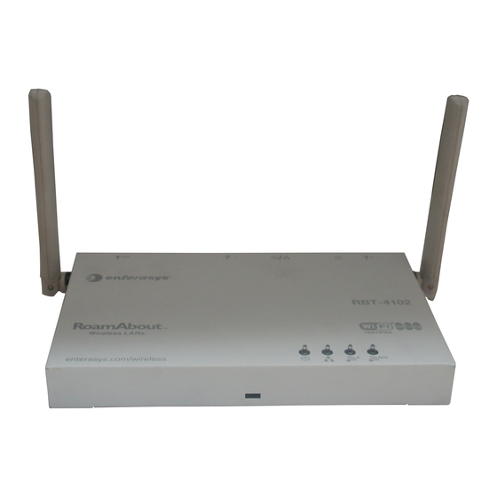
- Page 1 RoamAbout RBT-4102 and RBT-4102-EU 2.4 GHz / 5 GHz Wireless Access Point Installation Guide P/N 9034148-02...
- Page 3 ENTERASYS, ENTERASYS NETWORKS, ENTERASYS ROAMABOUT, LANVIEW, NETSIGHT, ROAMABOUT, WEBVIEW, and any logos associated therewith, are trademarks or registered trademarks of Enterasys Networks, Inc. in the United States and other countries. All other product names mentioned in this manual may be trademarks or registered trademarks of their respective companies.
- Page 4 This document is an agreement (“Agreement”) between the end user (“You”) and Enterasys Networks, Inc. on behalf of itself and its Affiliates (as hereinafter defined) (“Enterasys”) that sets forth Your rights and obligations with respect to the Enterasys software program/firmware installed on the Enterasys product (including any accompanying documentation, hardware or media) (“Program”) in the package and prevails over any additional, conflicting or inconsistent...
- Page 5 52.227-19 (a) through (d) of the Commercial Computer Software-Restricted Rights Clause and its successors, and (iii) in all respects is proprietary data belonging to Enterasys and/or its suppliers. For Department of Defense units, the Program is considered commercial computer software in accordance with DFARS section 227.7202-3 and its successors, and use, duplication, or disclosure by the...
- Page 6 (i) license fees due and paid, and (ii) the use, copying and deployment of the Program. You also grant to Enterasys and its authorized representatives, upon reasonable notice, the right to audit and examine during Your normal...
- Page 7 Agreement shall be void and a breach of this Agreement. 12. WAIVER. A waiver by Enterasys of a breach of any of the terms and conditions of this Agreement must be in writing and will not be construed as a waiver of any subsequent breach of such term or condition.
- Page 8 Notice...
- Page 9 Compliances RBT-4102 Federal Communication Commission Interference Statement This equipment has been tested and found to comply with the limits for a Class B digital device, pursuant to Part 15 of the FCC Rules. These limits are designed to provide reasonable protection against harmful interference in a residential installation. This equipment generates, uses and can radiate radio frequency energy and, if not installed and used in accordance with the instructions, may cause harmful interference to radio communications.
- Page 10 Industry Canada - Class B This digital apparatus does not exceed the Class B limits for radio noise emissions from digital apparatus as set out in the interference-causing equipment standard entitled “Digital Apparatus,” ICES-003 of Industry Canada. Cet appareil numérique respecte les limites de bruits radioélectriques applicables aux appareils numériques de Classe B prescrites dans la norme sur le matérial brouilleur: “Appareils Numériques,”...
- Page 11 EC Conformance Declaration Marking by the above symbol indicates compliance with the Essential Requirements of the R&TTE Directive of the European Union (1999/5/EC). This equipment meets the following conformance standards: • EN 60950 (IEC 60950) - Product Safety • EN 301 893 - Technical requirements for 5 GHz radio equipment •...
- Page 12 Hierbij verklaart Enterasys dat het toestel Radio LAN device in overeen- stemming is met de essentiële eisen en de andere relevante bepalingen van richtlijn 1999/5/EG Bij deze Enterasys dat deze Radio LAN device voldoet aan de essentiële eisen en aan de overige relevante bepalingen van Richtlijn 1999/5/EC. French Par la présente Enterasys déclare que l'appareil Radio LAN device est...
- Page 13 µε την παρουσα Enterasys δηλωνει οτι radio LAN device συµµορφωνεται προσ τισ ουσιωδεισ απαιτησεισ και τισ λοιπεσ σΧετικεσ διαταξεισ τησ οδηγιασ 1999/5/εκ Italian Con la presente Enterasys dichiara che questo Radio LAN device è con- forme ai requisiti essenziali ed alle altre disposizioni pertinenti stabilite dalla direttiva 1999/5/CE. Spanish...
- Page 14 France and Peru only This unit cannot be powered from IT † supplies. If your supplies are of IT type, this unit must be powered by 230 V (2P+T) via an isolation transformer ratio 1:1, with the secondary connection point labelled Neutral, connected directly to earth (ground). Impédance à...
- Page 15 • Le coupleur d’appareil (le connecteur du groupe et non pas la prise murale) doit respecter une configuration qui permet un branchement sur une entrée d’appareil EN 60320/IEC 320. • La prise secteur doit se trouver à proximité de l’appareil et son accès doit être facile. Vous ne pouvez mettre l’appareil hors circuit qu’en débranchant son cordon électrique au niveau de cette prise.
- Page 16 • Das Gerät muß an eine geerdete Steckdose angeschlossen werden, welche die internationalen Sicherheitsnormen erfüllt. • Der Gerätestecker (der Anschluß an das Gerät, nicht der Wandsteckdosenstecker) muß einen gemäß EN 60320/IEC 320 konfigurierten Geräteeingang haben. • Die Netzsteckdose muß in der Nähe des Geräts und leicht zugänglich sein. Die Stromversorgung des Geräts kann nur durch Herausziehen des Gerätenetzkabels aus der Netzsteckdose unterbrochen werden.
-
Page 17: Table Of Contents
Table of Contents Chapter 1: Introduction Package Checklist Hardware Description Component Description Chapter 2: Hardware Installation Chapter 3: Network Configuration Network Topologies Ad Hoc Wireless LAN (no Access Point) Infrastructure Wireless LAN Infrastructure Wireless LAN for Roaming Wireless PCs Infrastructure Wireless Bridge Appendix A: Troubleshooting Diagnosing Access Point Indicators Appendix B: Cables and Pinouts... - Page 18 Contents...
-
Page 19: Chapter 1: Introduction
Chapter 1: Introduction The RoamAbout RBT-4102 and RBT-4102-EU are IEEE 802.11a/b/g access points that provide transparent, wireless high-speed data communications between the wired LAN and fixed or mobile devices equipped with an 802.11a, 802.11b, or 802.11g wireless adapter. This solution offers fast, reliable wireless connectivity with considerable cost savings over wired LANs (which include long-term maintenance overhead for cabling). -
Page 20: Package Checklist
Introduction Package Checklist The RoamAbout package includes: • One RoamAbout RBT-4102 (North America) or RBT-4102-EU (Europe and Japan) • One Category 5 network cable • One RS-232 console cable • One AC power adapter and power cord • Four rubber feet •... - Page 21 Hardware Description Rear Panel External Antenna DC Power Reset Security External Antenna RJ-45 Port, Console Connector Supply Button Slot Connector Port (802.11b/g) Radio Connector (802.11a Radio)
-
Page 22: Component Description
For a list of external antennas, their model type and gain refer to “External Antennas” on page C-7. For information on the external antennas available, refer to the following document on the Enterasys Web site: http://www.enterasys.com/support/manuals/n-s.html#R LED Indicators... - Page 23 Hardware Description Status Description Link On Green Indicates a valid 10/100 Mbps Ethernet cable link. Flashing Green Indicates that the access point is transmitting or receiving data on a 10/100 Mbps Ethernet LAN. Flashing rate is proportional to your network activity. On Green Indicates the 802.11a radio is enabled.
- Page 24 Introduction Reset Button This button is used to reset the access point or restore the factory default configuration. If you hold down the button for less than 5 seconds, the access point will perform a hardware reset. If you hold down the button for 5 seconds or more, any configuration changes you may have made are removed, and the factory default configuration is restored to the access point.
-
Page 25: Chapter 2: Hardware Installation
Chapter 2: Hardware Installation To install the access point, follow the steps outlined below: Select a Site – Choose a proper place for the access point. In general, the best location is at the center of your wireless coverage area, within line of sight of all wireless devices. - Page 26 Hardware Installation Mounting Slots Attaching Slats Bottom of Access Point The access point should be mounted only to a wall or wood surface that is at least 1/2-inch plywood or its equivalent. To mount the access point on a wall, always use its wall-mounting bracket.
- Page 27 Hardware Installation Mounting Points Fastening Screw Align this tab with the Fastening Screw Mounting Slots Bracket Lock the Access Point in Place – To prevent unauthorized removal of the access point, you can use a Kensington Slim MicroSaver security cable (not included) to attach the access point to a fixed object.
- Page 28 Hardware Installation Connect the Power Cord – Connect the power adapter to the access point, and the power cord to an AC power outlet. Otherwise, the access point can derive its operating power directly from the RJ-45 port when connected to a device that provides IEEE 802.3af compliant Power over Ethernet (PoE).
-
Page 29: Chapter 3: Network Configuration
Chapter 3: Network Configuration Wireless networks support a standalone configuration as well as an integrated configuration with 10/100 Mbps Ethernet LANs. The RoamAbout RBT-4102 and RBT-4102-EU also provide repeater and bridging services that can be configured independently on either the 5 GHz or 2.4 GHz radio interfaces. -
Page 30: Network Topologies
Network Configuration Network Topologies Ad Hoc Wireless LAN (no Access Point) An ad hoc wireless LAN consists of a group of computers, each equipped with a wireless adapter, connected via radio signals as an independent wireless LAN. Computers in a specific ad hoc wireless LAN must therefore be configured to the same radio channel. -
Page 31: Infrastructure Wireless Lan For Roaming Wireless Pcs
Network Topologies Wired LAN Extension to Wireless Clients Server Switch Desktop PC Access Point Notebook PC Desktop PC Infrastructure Wireless LAN for Roaming Wireless PCs The Basic Service Set (BSS) defines the communications domain for each access point and its associated wireless clients. The BSS ID is a 48-bit binary number based on the access point’s wireless MAC address, and is set automatically and transparently as clients associate with the access point. -
Page 32: Infrastructure Wireless Bridge
Network Configuration Seamless Roaming Between Access Points Server Desktop PC Switch Switch Access Point Notebook PC Notebook PC Access Point <BSS 2> <BSS 1> <ESS> Desktop PC Infrastructure Wireless Bridge The IEEE 802.11 standard defines a Wireless Distribution System (WDS) for bridge connections between BSS areas (access points). - Page 33 Network Topologies Wireless Bridge Links Network Between Access Points Core 802.11g Radio Root Bridge AP Link 802.11a Radio Bridge Link 802.11g Radio Bridge AP Link 802.11a Radio Bridge Link 802.11a Radio Bridge Link 802.11g Radio Bridge AP Link 802.11g Radio Bridge AP Link...
- Page 34 Network Configuration...
-
Page 35: Appendix A: Troubleshooting
Appendix A: Troubleshooting Diagnosing Access Point Indicators Troubleshooting Chart Symptom Action Power LED is Off • AC power adapter may be disconnected. Check connections between the access point, the power adapter, and the wall outlet. • PoE power to the access point may be disabled at the connected switch port. - Page 36 Troubleshooting...
-
Page 37: Appendix B: Cables And Pinouts
Appendix B: Cables and Pinouts Twisted-Pair Cable Assignments For 10/100BASE-TX connections, a twisted-pair cable must have two pairs of wires. Each wire pair is identified by two different colors. For example, one wire might be green and the other, green with white stripes. Also, an RJ-45 connector must be attached to both ends of the cable. -
Page 38: Straight-Through Wiring
Cables and Pinouts MDI Signal Name MDI-X Signal Name Receive Data plus (RD+) Transmit Data plus (TD+) and GND (Positive V and -48V feeding power (Negative V port port Receive Data minus (RD-) Transmit Data minus (TD-) and GND (Positive V and -48V feeding power (Negative V port port... -
Page 39: Crossover Wiring
Console Port Pin Assignments Crossover Wiring If the twisted-pair cable is to join two ports and either both ports are labeled with an “X” (MDI-X) or neither port is labeled with an “X” (MDI), a crossover must be implemented in the wiring. EIA/TIA 568B RJ-45 Wiring Standard 10/100BASE-TX Crossover Cable White/Orange Stripe... -
Page 40: Wiring Map For Serial Cable
Cables and Pinouts Wiring Map for Serial Cable Table B-1. 10/100BASE-TX MDI and MDI-X Port Pinouts Switch’s 9-Pin Serial Port Null Modem PC’s 9-Pin DTE Port 2 RXD <---------RXD ------------ 3 TxD 3 TXD -----------TXD ----------> 2 RxD 5 SGND -----------SGND ---------- 5 SGND Note: he left hand column pin assignments are for the male DB-9 connector on the access point. -
Page 41: Appendix C: Specifications
Appendix C: Specifications General Specifications Maximum Channels 802.11a: RBT-4102 US & Canada: 13 (normal mode), 5 (turbo mode) RBT-4102-EU Japan: 4 (normal mode) ETSI: 11 channels (normal mode), 4 (turbo mode) 802.11b/g: RBT-4102 FCC/IC: 1-11 RBT-4102-EU ETSI: 1-13 France: 10-13 Data Rate 802.11a: Normal Mode: 6, 9, 12, 18, 24, 36, 48, 54 Mbps per channel... - Page 42 Specifications Operating Frequency 802.11a: 5.15 ~ 5.25 GHz (lower band) US/Canada, Japan, Europe 5.25 ~ 5.35 GHz (middle band) US/Canada, Europe 5.725 ~ 5.825 GHz (upper band) US/Canada 5.50~ 5.70 GHz Europe 802.11b/g: 2.4 ~ 2.4835 GHz (US, Canada, ETSI) 2.4 ~ 2.497 GHz (Japan) AC Power Adapter Input: 100-240 AC, 50-60 Hz...
- Page 43 General Specifications Compliances FCC Class B (US) ICES-003 (Canada) RTTED 1999/5/EC VCCI (Japan) RCR STD-33A Radio Signal Certification FCC Part 15C 15.247, 15.207 (2.4 GHz) FCC Part 15E 15.407 (5 GHz) RSS-210 (Canada) EN55022:1998, EN55024:1998, EN61000-3-2:2000, EN61000-3-3:1995, EN 301.893, EN 300.328, EN 301.489-1, EN 301.489-17 MPT RCR std.33 (D33 1~13 Channel, T66 Channel 14) Safety UL/CUL (CSA 22.2 No.
-
Page 44: Sensitivity
Specifications IEEE 802.11g Data Rate Sensitivity (dBm) 17 Mbps 24 Mbps 36 Mbps 48 Mbps 54 Mbps IEEE 802.11b Data Rate Sensitivity (dBm) 1 Mbps 2 Mbps 5.5 Mbps 11 Mbps... -
Page 45: Transmit Power
General Specifications Transmit Power IEEE 802.11a Maximum Output Power (GHz - dBm) Data Rate 5.15-5.250 5.25-5.350 5.50-5.700 5.725-5.825 6 Mbps 9 Mbps 12 Mbps 8 Mbps 24 Mbps 36 Mbps 48 Mbps 54 Mbps IEEE 802.11g Maximum Output Power (GHz - dBm) Data Rate 2.412 2.417~2.467... -
Page 46: Operating Range
Specifications Operating Range Note: The operating range distances listed in the following tables are for typical environments only. Operating ranges can vary considerably depending on factors such as local interference and barrier composition. It is recommended to do a site survey to determine the maximum ranges for specific access point locations in your environment. -
Page 47: External Antennas
RBTES-AH-P23M 5.7–5.8 GHz Directional, outdoor 23 dBi RBTES-AW-S1590M 4.9–6.0 GHz Adjustable Sector, outdoor 15 dBi/90° 16 dBi/60° For further information on the external antennas supported by the access point, refer to the following document on the Enterasys Web site: http://www.enterasys.com/support/manuals/n-s.html#R... - Page 48 Specifications...
- Page 50 E102005-R02 150000031200E...
Need help?
Do you have a question about the RoamAbout RBT-4102 and is the answer not in the manual?
Questions and answers