Table of Contents

Related Manuals for EverFocus EZ650


Summary of Contents for EverFocus EZ650
- Page 1 EverFocus Operation Instruction...
-
Page 2: Operation Instruction
All specifications are therefore subject to change without notice. All rights reserved. No part of the contents of this manual may be reproduced or transmitted in any form or by any means without written permission of the EverFocus Electronics Corporation. - Page 3 Precautions 1. Do not place any object on top of the cover. 2. Be careful when handling the camera, do not drop it or subject it to strong shock or vibration to prevent any damages to it. Do not disassemble it or place it on an unstable base. 3.
- Page 4 Federal Communi c ati o n Commi s si o n Interference Statement This equipment has been tested and found to comply with the limits for a Class B digital device, pursuant to Part 15 of the FCC Rules. These limits are designed to provide reasonable protection against harmful interference in a residential installation.
-
Page 5: Table Of Contents
Table of Contents 1.1 FEATURES............................6 1.2 ACCESSORY PARTS LIST ......................7 1.3 SPECIFICATIONS ..........................8 1.4 DIMENSIONS ............................. 9 1.5 CAMERA COMPONENT DESCRIPTION ................... 11 1.6 BACK PANEL LAYOUT ......................... 12 1.7 RELATED PRODUCTS........................13 2.1 WIRING AND MOUNTING......................13 2.2 ADJUSTING CAMERA POSITION.................... -
Page 6: Features
0.05 lux before the added benefits of advanced DSP technology, delivered by a 1/3” Sony Super HAD CCD II sensor, is just the beginning with the new EverFocus EZ650. A 6-50mm varifocal auto-iris lens combined with high output IR illuminators delivers a useful range of over 80m/261ft.Mount the optional EIR100 auxiliary illuminator and increase the range to over... -
Page 7: Accessory Parts List
Please Note: If an item appears to have been damaged in shipment, replace it properly in its carton and notify the shipper. If any items are missing, notify your EverFocus Electronics Corp. Sales Representative or Customer Service. The shipping carton is the safest container in which the unit may... -
Page 8: Specifications
1.3 Specifications Product Model EZ650 Pickup Device 1/3” SONY Super HAD CCD Ⅱ Video Format NTSC or PAL Picture Elements 768 x 494 (NTSC)/752 x 582 (PAL) Horizontal Resolution 560 TV Lines Sensitivity 0.05Lux/F=1.2(AGC ON); 0.0002Lux/F=1.2 (IR off ,Sens-up 256x Max; ~8X recommened) 0 Lux (IR On) S/N Ratio Over 52dB (AGC off) -
Page 9: Dimensions
1.4 Dimensions Drilling Dimension of holes to holes 45mm/1.8” 80mm/3.2” Dimension of Bracket 220.5mm/8.68” 84mm/3.31” 106.5mm/4.19 112.7mm/4.44 199mm/7.83”... - Page 10 Dimension of whole camera with bracket 275mm/10.8” 107.5mm/4.3” 243.5mm/9.74” 357mm/14” Dimension of whole camera with bracket and EPR100...
-
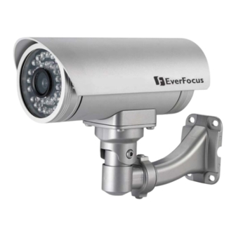
Page 11: Camera Component Description
1.5 Camera Component Description Sun shield Fixing screw for sunshield Bracket Power connector RS485 terminal Video output Control key selection switch Control key EZ650 Component description... -
Page 12: Back Panel Layout
1.6 Back Panel Layout 24VAC model (for 24VAC 110V~240VAC model (for Power Only) 110V ~240V Power only) 1. Video Output Connector Connect the video output of the camera to a color monitor or other video devices through a 75 Ohm type coaxial cable with BNC female connector at backside of the camera. 2. -
Page 13: Related Products
7. Cable clips Used to fix power cable and RS485 cable. 1.7 Related Products In addition, you may order the following EverFocus products which are recommended for use with the camera to achieve the best performance: EverFocus control keyboard (EKB500) -
Page 14: Wiring And Mounting
Chapt e r 2. Installation This chapter will describe, in general terms, how to install the EZ650 camera. STEPS: 1. Wire and mount the camera. See 2.1 2. Adjust the camera position. See 2.2 3. Adjust Lens. See 2.3 4. Connect to Keyboard (Optional) See 2.4 Warning To prevent electrical shock, turn off the electrical power before making electrical ... - Page 15 2. Fix the bracket to wall by using 4 screws. Coaxial cable Power cable RS485 cable 3. Open camera’s back cover: Loose the 2 screws from the back panel cover, then open the back cover. Screws for back panel...
- Page 16 Take off the cap of waterproof conduit which is at the camera bottom. Power cable (Φ10.3mm) Coaxial cable RS485 (Φ6mm) (Φ5mm) Note: 1. the holes of waterproof conduit were plugged, please remove the plug when you need to use it for connection. 5.
- Page 17 Coaxial cable Power cable RS485 cable Note: 1. Power cable’s diameter must be less than 10 mm 2. Only use RG59/5C2V for Video cable 3. RS485 cable must be less then 5 mm 6. Close the waterproof cap and fix waterproof conduit to the base of camera firmly. 7.
- Page 18 8. Connect RG59 coaxial cable with BNC connector. 9. Unscrew both cable clips, wire power cable and RS485 cable through the cable clips. Then, screw the cable clips to rear panel. a. Connecting Power-24VAC model: connect 24VAC power on N and L Model: Connect PE, N and L.
-
Page 19: Adjusting Camera Position
Screws for back panel 2.2 Adjusting Camera Position Adjust camera’s angle vertically or horizontally by using hex key included in package. Loose this screw to make angle adjustment vertically Loose this screw to make angle adjustment horizontally... -
Page 20: Adjusting Lens
2.3 Adjusting Lens Open camera’s base, a control key is attached at inner side of the base. Detach the control key and use this key for OSD or Lens setting. 2.3.1 Lens Setting Please turn the control key selection switch at the back panel to “Lens”.( ). -
Page 21: Keyboard Connection (Optional)
Please refer to Chapter 4 for more details of Keyboard control. Connect the cable from keyboard’s RS485 port to camera’s RS485 port. (Keyboard is an optional accessory). RS485 connecting accessories are included in Everfocus Keyboard package. Connect the cable from video output jack of the camera to monitor’s input jack. -
Page 22: Control Key General Operation Guide
Chapt e r 3. OSD Menu & Configuration This chapter introduces how to configure the camera OSD menu. 3.1 Control Key General Operation Guide Please turn the control key selection switch at the back panel to “OSD” ”( Use the control key to do OSD menu setting. Mini-Joystick The Cursors &... - Page 23 When the item with sub-menu is selected, press the mini-joystick to switch to the sub-menu for further settings. Please refer to the diagram below. SETUP LENS DC <┘ > LENS SHUTTER LEVEL |+++++++++| 25 WHITE BAL. BACKLIGHT Sub-Menu MIDDLE Main Menu s Menu AUTO <┘...
-
Page 24: Rs485 Id & Baud Rate Setting
3.2 RS485 ID & Baud Rate Setting Note: This section is optional preserved for the people that want to change camera ID and baud rate. In most situations, we suggest you can just use Camera ID-01 and Baud Rate-9600, Protocol-Pelco D on keyboard, then it would work. - Page 25 A B C D E F G H I J K L M N O P Q R S T U V W X Y Z a b c d e f g h i n o p q r s t u v w x y z ─...
- Page 26 d. DATA STORED- Confirm with you that the last 3 settings you have made will be saved. A B C D E F G H I J K L M N O P Q R S T U V W X Y Z a b c d e f g h i n o p q r s t u v w x y z ─...
-
Page 27: Osd Menu Setup
3.3 OSD Menu Setup 3.3.1 OSD Menu Tree Default settings are shown bold or in brackets. Lens — DC — Brightness 0~100 (50) Exposure — Shutter — x256, x128, x64, x32, x16, x8, x4, x2, 1/60(NTSC) / 1/50 (PAL), FLK,1/250, 1/500, 1/1000, 1/2000, 1/5000, 1/10000 —... - Page 28 — Motion — Off — On — Area Select — Area1-Area4 — Area Display — Off, On — Left/Right — 5~66 — Width — 0~93 — Top/Bottom — 1~60 — Height — 0~60 — Sensitivity — 0~40 — Motion View —...
-
Page 29: Lens
3.3.2 LENS When the SETUP menu is displayed on the screen, please direct the arrow to point to “LENS” by using the UP and DOWN buttons. The iris opening can be adjusted in DC mode in LENS LEVEL. The level can be adjusted from 0 to 50. -
Page 30: Blc-Backlight Compensation
NOTE: 1. SENS-UP will be disabled, if AGC is OFF or the default SHUTTER value (1/50 PAL / 1/60 NTSC) was changed 2. The image becomes brighter when the setting increases; however, the after image increases as well. Due to the increased light sensitivity of the Super HAD II chip, far less DSP ‘boost’... -
Page 31: D-Wdr
1. Please direct the arrow to point to “BLC” by using the UP and DOWN buttons. 2. Select the HSBLC mode by pressing the LEFT or RIGHT button. Then make adjustments as below: LEVEL Adjust the sensitivity level for HSBLC from 0 to 8. DEFAULT Set the factory default values for HSBLC. -
Page 32: White Balance Control
3.3.4 WHITE BALANCE CONTROL The screen color can be adjusted by using the WHITE BALANCE function. Please direct the arrow to point to “WHITE BAL” by using the UP and DOWN buttons. Please select the mode you would like to operate by pressing the LEFT or RIGHT button. Please select one of the 6 modes below: Auto Tracking White Balance: This mode can be used within the color temperature range from 5,500°K to 6,000°K (eg, fluorescent light, outdoor,... -
Page 33: 3Dnr
Press “RET” to save all settings in the DAY/NIGHT menu and returns to the previous menu. Press “END” to save all the setting menus and exit. COLOR The picture is always displayed in color, even at low light levels. NOTE: In “color” operation, there is an IR “cut” (blocking) filter between the lens and the sensor;... -
Page 34: D-Effect
Please direct the arrow to point to “CAM TITLE” by using the UP or DOWN button. Select “ON” by pressing the LEFT or RIGHT button. Press SETUP button. Maximum 15 characters can be used for the ID. Use UP, DOWN, LEFT and RIGHT buttons to move the cursor to the letter to be chosen. Use SETUP button to choose that letter. -
Page 35: D-Zoom
3.3.7.5 D-ZOOM Setup for digital zoom. Disable the D-ZOOM function D-Zoom: Select digital zoom from X1.0 up to X32. Note that zoom levels above X4 may lead to excessive pixellation. Setup of the position of the magnified image in view (0 is the center of the image): Pan: Select digital pan from -100 to 100. -
Page 36: Privacy
the sensitivity value is high, motion detection sensitivity increases to sense very small movements and vice versa. MOTION VIEW Select “ON” to display motion detection pixels in the live view. RETURN Press “RET” to save all settings in MOTION menu and return to the previous menu. -
Page 37: Sharpness
3.3.8.1 SHARPNESS The contour of the video image becomes cleaner and more easily distinguished as the level of SHARPNESS increases. If the level is set too high, it may affect the video image and cause noise. The available range of level is 0~31. 3.3.8.2 BLUE Adjust image’s blue level. -
Page 38: Key Features With Keyboard
Chapt e r Control from Keyboard EKB500 (Optional) Note! Before being able to control keyboard, make sure Keyboard RS485 camera ID, Baud rate match the camera. (see COM port setting in EKB500 manual). EZ650 camera ID default is 01. Baud rate is 9600. -
Page 39: Lens Adjustment By Keyboard
d. Move the joystick RIGHT () and LEFT () to adjust the mode and parameters of the selected item. e. Press “Menu” to leave and goes to previous menu after setting. Move to “exit” and press “menu” button when you finish all settings. f. - Page 40 EverFocus USA - California: EverFocus USA - New York: 1801 Highland Avenue, Unit A, Duarte, CA 415 Oser Avenue, Unit S, Hauppauge, NY 11788, 91010, USA TEL: +1 626 844 8888 TEL: +1 631 436 5070...
Need help?
Do you have a question about the EZ650 and is the answer not in the manual?
Questions and answers