Table of Contents
Advertisement
Available languages
Available languages
Advertisement
Table of Contents

Related Manuals for COMFORT-AIRE BGE-123A


Summary of Contents for COMFORT-AIRE BGE-123A
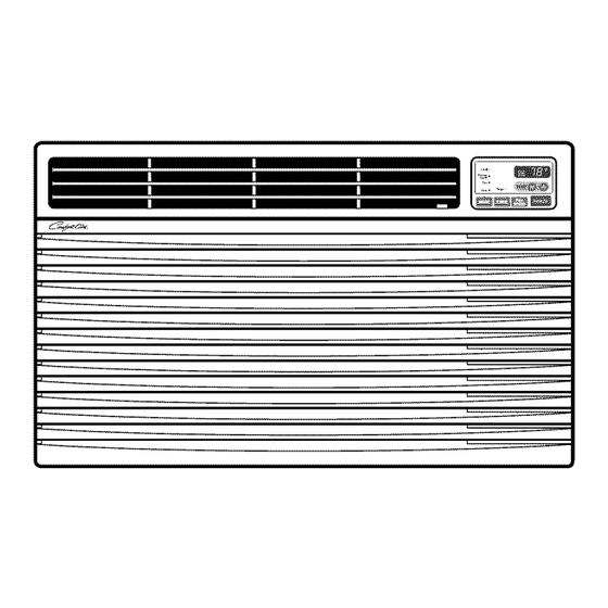
- Page 1 Models: BGE-103A BGE-123A...
-
Page 2: For Your Records
FOR YOUR RECORDS Write the model and serial numbers here: Model # Serial # You can find them on a label on the side of each unit. Dealer's Name Date Purchased • Staple your receipt to this page in the event you need it to prove date of purchase or for warranty issues. -
Page 3: Safety Precautions
Safety Precautions To prevent injury to the user or other people and property damage, the following instructions must be followed. • Incorrect operation due to ignoring instruction will cause harm or damage. The seriousness is classified by the following indications. ,WARNING kCAUTION This symbol indicates the possibility of death or serious injury. - Page 4 Safety Precautions • Operation • It will cause electric shock or • There is danger of fire or ° Otherwise, it may cause a electric shock. fire or electrical shock. fire due to heat generation. • The appearance of the air •...
- Page 5 Safety Precautions • It will cause electric shock or • It will cause electric shock or • It will cause electric shock. fire. fire due to heat generation. ® ® • It may cause electric shock ° Otherwise, it may cause •...
- Page 6 Safety Precautions • Operation • It may cause injury. • It may cause product failure. • The appearance of the air conditioner may deteriorate, change color, or develop surface flaws. • It contains containments and ° It may cause an injury •...
- Page 7 Prior to Operation 1. Contact an installation specialist for installation. 2. Plug in the power plug properly. 3. Use a dedicated circuit. 4. Do not use an extension cord. 5. Do not start/stop operation by plugging/unplugging the power cord. 6. If the cord/plug is damaged, replace it with only an authorized replacement part.
- Page 8 Introduction & This symbol alerts you to the risk of electric shock. This symbol alerts you to hazards that could cause harm to the air conditioner. This symbol indicates special notes. _WARNING This appliance should be installed in accordance with the National Electric Code. THE SLEEVE AND THE REAR GRILLE (optionally supplied with your unit) SLEEVE...
-
Page 9: Electrical Safety
Electrical Safety 115V- 230V- Power cord may include a current interrupter device, A test and reset button is provided on the plug case. The device should be tested on a periodic basis by first ¢....% pressing the TEST button and then the RESET button, If the TEST button does not trip or if the RESET button will not stay engaged, discontinue use of the air... - Page 10 Electrical Safety IMPORTANT DO NOT CUT OR REMOVE THE THIRD (GROUND) PRONG FROM THE POWER PL UG. (PLEASE READ CAREFULLY) FOR THE USER'S PERSONAL SAFETY, THIS A. SITUATIONS WHEN THE APPLIANCE WILL BE APPLIANCE MUST BE PROPERLY GROUNDED DISCONNECTED OCCASIONALLY: Because of potential safety hazards, we strongly The power cord of this appliance...
-
Page 11: Installation Requirements
Installation INSTALLATION HARDWARE Remove packing sheet from the back of the sleeve, and packing corner and blue tape from the air conditioner. INSTALLATION REQUIREMENTS If you use an existing wall sleeve, you should measure its dimensions. 2 Size options Install the new air conditioner according to these installation... -
Page 12: How To Install
Installation INSTALLATION CAUTION All wall sleeves used to mount the new Air Conditioner must be in sound structural condition We strongly recommend the removal of the and have a rear grille that securely attaches old wall sleeve and the installation of a new sleeve, or rear flange that serves as a stop for the... - Page 13 Installation PROCEDURE If you are using the new sleeve (optionally Install the new unit into the wall sleeve. supplied with your unit),skip to step 3. Otherwise, install the plastic grille from the kit. _J_To assemble trim, snap the tab of each piece into the slot of the other piece as shown below.
-
Page 14: Installation
Installation PROCEDURE Remove the backing from the Horizontal Insulation strip 13/8x 5/8 x 273/16 and attach that to the inside bottom of the sleeve as shown edirect the louvers at the back of the wall sleeve to 60 ° angle as shown in the FIG 9. - Page 15 Installation PROCEDURE • , CAUTION emove the backing from the support blocks and attach them to the inside of the wall sleeve • Air conditioners covered in this manual pose as shown FIG 15. Slide the baffle into slots of an excessive weight hazard.
- Page 16 Installation PROCEDURE Remove the backing from the Horizontal Insulation strip 13/8 x 13/8 x 273/16 and attach that to the inside bottom of the sleeve edirect the louvers at the back of the wall sleeve to 60 ° angle as shown in the FIG 17.
- Page 17 Installation PROCEDURE To assemble trim, snap the tab of each piece into the slot of the other piece as shown below. Slide trim over the front of the air conditioner Remove the backing from the 13" shim strips and attach them as shown below in Fig.
-
Page 18: Fan Speed
Operating Instructions The controls will look like one of the following. -FAN SPEED • Every time you push this button, it advances the setting as follows: {High[ F2 ] _ Low[ F1 ] _ High[ F2 ]} REMOTE CONTROL SIGNAL RECEIVER Coom q Energy @... -
Page 19: Temperature Setting
Operating Instructions The remote control and control panel will look like one of the following pictures. POWER • To turn the air conditioner ON, push this button. To turn the air conditioner OFF, push the button again. • This button takes priority over any other button. Power •... - Page 20 Operating Instructions 1. Remove the cover from the back of the remote • Do not use rechargeable batteries. controller. Such batteries differ from standard dry cells in shape, dimensions, and 2. Insert two batteries. performance. • Be sure that the (+) and (-) directions are •...
-
Page 21: Maintenance
Maintenance and Service TURN THE AIR CON mONERREMOVE THE PLUG ROM T HE POWER OUTLET The air filter should be checked at least twice a month to see if cleaning is necessary. Trapped particles in the filter will build up and block the airflow. This reduces the cooling capacity and also causes an accumulation of frost on the cooling coils. - Page 22 Maintenance and Service ,,Youmay hear a pingingnoise causedby water beingpickedup andthrown againstthe condenseron rainy days or when the humidityis high.This designfeaturehelps removemoistureand improveefficiency. ,,Youmay hear the thermostatclickwhen the compressor cycleson andoff. • Waterwill collectin the basepan duringhigh humidityor on rainydays.The watermay overflowand drip from the outdoor side of the unit.
- Page 23 Memo Owner's Manual...
- Page 24 PARA SUS ARCHIVOS Escriba aqd el modelo y nL_merode serie: Modelo n°: Serie n°: Puede encontrar estos datos en la etiqueta situada en el lateral de cada unidad. Nombre del distribuidor: Fecha de compra: • Adjunte su recibo a esta p_gina con la grapadora para el momento que Io necesite para probar la fecha de su adquisici6n o para la validaci6n de la garanfia.
- Page 25 Precauciones deseguridad Para evitar lesiones al usuario o a otras personas y dafios a la propiedad, estas instrucciones esten seguirse. • Unaoperacionincorrectapot ignorarlas instrucciones provocaralesioneso dafios.La seriedadse clasifica por lassiguientesindicaciones. ADVERTENCIA Este s[mboloindica la posibilidadde muerteo de seria lesi6n. PRECAUCION Este s[mboloindica s61ola posibilidadde lesioneso dafios a la propiedad •...
- Page 26 Precauciones de seguridad • Operacion • Puede ocasionar una • De Iocontrario,puedeprovocar • De Io contrario,podr[a provocar explosi6n o descarga unadescargaelectricao incendio un incendio o descarga electrica. electrica. debidoa la generacionde calor. • ">? • Puede ocasionar un incendio • Puede provocar fallos en el •...
- Page 27 Precauciones deseguridad • De Io contrario, puede • Provocara.descargas • Provocara. descargas electricas o incendios. electricas. provocar una descarga electrica o incendio debido a la generaci6n de calor. ® • Podria ocasionar una • De Io contrario, podria ocurrir • Son puntiagudas y pueden descarga electrica y daSos.
- Page 28 Safety Precautions • Operacion • Podria ocasionar lesiones. • Puede causar una averia en • La aparienciadel aparatode aire el aparato. acondicionado puededeteriorar, cambiarel coloro desarrollar flujosen lassuperficies. • Puede lesionarse al caerse • El funcionamiento sin filtros del aparato o al caerse los puede provocar fallos.
- Page 29 Antes de la Operacion 1. Contactar un especialista para la instalaci6n. 2. Coloque el enchufe correctamente. 3. No comparta la salida con otros artefactos. 4. No use un cable de extensi6n. 5. No arranque/detenga el funcionamiento enchufando/desenchufando el cable de corriente electrica. 6.
- Page 30 Introduccion Este simbolo Io advierte de un peligro de accidente por corriente electrica. Este sfmbolo Io adiverte de un peligro que pueda causar un daho del ventliador. Este sfmbolo significa condicciones especiales. ADVERTENCIA Este aparato deberia instalarse de acuerdo con las normas del C6digo Electrico Nacional. EL SOPORTE DE PAREDY LA REJILLA POSTERIOR (incluido opcionalmente...
- Page 31 Seguridad el#ctrica 115V~ 230V~ El cable de alimentaci6n puede incluir un dispositivo interruptor de corriente. La carcasa del enchufe cuenta con un bot6n de prueba y otto de reinicio. El dispositivo debe comprobarse peri6dicamente presionando primero el bot6n TEST y despues RESET. Si el bot6n TEST no se desconecta o si el bot6n RESET no permanece active, ",, [ ZZIi/...
- Page 32 Seguridad el#ctrica IMPORTANTE NO CORTE0 REMUEVALA TERCERAPATA(GROUND) DEL ENCHUFE. (FAVORLEA CON ATENCION) PORLASEGURIDAD P ERSONAL D ELUSUARIO, ESTE A. SITUACIONES EN LAS CUALESEL APARATO APARATO D EBE SERDEB[DAMENTE NEUTRALIZADO. ES DESCONECTADO OCASIONALMENTE: El cord6n de energfa de este aparato esta equipado Debido al peligro potencial, nosotros no con tres patas(cable a tierra).
-
Page 33: Requisitos De Instalacion
Instalacion EQUIPO DE INSTALACION Extraiga la lamina de embalaje del alojamiento aparato de aire acondicionado y la esquinera y cinta azul del aparato de aire acondicionado. REQUISITOS DE INSTALACION Si utiliza un alojamiento de pared existente, debe tomar sus 2 opciones detama_o medidas. - Page 34 Instalacion INSTALACION &PRECAUCION Todos los alojamientos de pared utilizados para montar el $e recomienda encarecidamente la extracci6ndel nuevo aparato de a/re acondicionado deben estar en buenas antiguoalojamiento en la paredy la instalaci6n de un condiciones estructurales y tener una rejilla posterior que se nuevoalojamiento de paredComfort-Aim.
- Page 35 Instalacion PROCEDIMIENTO Instale la nueva unidad en el alojamiento de la pared. i esta.utilizando la nueva funda (suministrada opcionalmente con su unidad), vaya directamente al paso 3. _4J_ Para montar el reborde, inserte el saliente de cada En caso contrario, instale la rejilla pla.sticadel equipo. Corte pieza en la ranura de la otra pieza segt]n se rnuestra la rejilla de pla.sticoa 64,77 cm (25-1/2) de ancho y 38,74 abajo.
- Page 36 Instalacion PROCEDIMIENTO Extraiga la parte posterior de la tira de Aislamiento horizontal de 3,5 x 1,60 x 69,06 cm (13/8x 5/8x 273h6)y fijela a la parte inferior interna del alojarniento segQnse oloque la direcci6n de la rejilla en la parte posterior del alojamiento de la pared en un _.ngulo de 60°...
- Page 37 Instalacion PROCEDIMIENTO B A PRECAUCION xtraiga la parte posterior de los bloques de soporte y fijelos en el interior del alojarniento de la pared • Los aparatos de aire acondicionado de los que segt]n se rnuestra en la FIG 15. Deslice el deflector trata este manual constituyen un peligro de peso en las ranuras de los bloques de soporte.
- Page 38 Instalacion PROCEDIMIENTO Extraiga la parte posterior de la tira de Aielamiento horizontal de 3,5 x 3,5 x 69,06 cm (13/8 x 13/8 x 273/16) y fijela a la parte inferior intema del alojamiento segt]n oloque la direcci6n de la rejilla en la parte posterior del alojamiento de la pared en un a.ngulode 600 segOnse se muestra abajo.
- Page 39 Instalacion PROCEDIMIENTO _'lPara montar el reborde, inserte el saliente de cada pieza en la ranura de la otra pieza segtJn se muestra abajo. Deslice el reborde sobre la parte frontal del xtraiga el refuerzo de las tiras de reborde 33,02 (13) y fijelas segt]n se rnuestra abajo en la FIG 24.
-
Page 40: Velocidad Del Ventilador
Instrucciones operativas La apariencia de los controles ser# como uno de los siguientes. -VELOCIDAD DEL VENTILADOR •Cada vez que presione este botdn, el ajuste cambiara, c omo sigue a continuacion:{Alto[ F2 ] * Bajo[ F1 ] _Alto[ F2 ]} RECEPTOR DESENALDEL MANDO A DISTANCIA Cool : Energy... - Page 41 Instrucciones operativas El mando a distancia y el panel de control se parecer4n a los de las siguientes im4genes. ENERGIA • Presioneeste boton para ENCENDERel aire acondicionado. Para APAGAR el aire acondicionadovuelva a presionar el boron. • Este botontiene prioridad sobrecualquierotro boton. AJUSTEDETEMPERATURA •...
- Page 42 Instrucciones operativas • No utilice bateris recargables, 1. Quite la tapa de la parte posterior del estas son diferentes de forma, telemando. Para ello haga deslizar la tapa de dimension y uso respecto a segtJn la direccidn della flecha. las baterias secas usuales. 2.
-
Page 43: Cuidado Y Mantenimiento
Cuidado yMantenimiento APAGUE EL ACONDICIONADOR DE AIREY DESENCHOFELO DE LA FUENTE DE PODER. El filtro de aire debe ser controlado al menos dos veces al rues para ver si es necesaria su lirnpieza. Las particulas atrapadas en el filtro pueden acumularse y bloquear el flujo del aire. - Page 44 Cuidado yMantenimiento • Puedequeescucheun ruidometdtlico c ausadoporelagua recogida y devueltahaciaelcondensador e n dfas Iluviosos o con alta humedad. E stacaracteristica del dise_oayudaa eliminarla humedad y mejorarla eficiencia. • Puedequeescuche el chasquidodeltermostato cuandoel compresor realizaciclosde encendido y apagado. • El aguaserecoger_, en la bandejade la baseen dfas Iluviosos o con alta humedad. P uedequeel aguarebosey caigadesdela parteexteriorde la unidad.
- Page 45 Nora Manual del u suario 23...
- Page 46 Nora Aire Acondicionado...
- Page 47 Specifications and performance data subject to change without notice. HEAT CONTROLLER, INC. 1900 WELLWORTH AVENUE • JACKSON, MICHIGAN 49203 THE QUALITY LEADER IN CONDITIONING AIR P/No: 3828A21015Q Printed in China...
Need help?
Do you have a question about the BGE-123A and is the answer not in the manual?
Questions and answers